US9407750B2 - Terminal device, information processing method and program - Google Patents
Terminal device, information processing method and program Download PDFInfo
- Publication number
- US9407750B2 US9407750B2 US14/434,310 US201314434310A US9407750B2 US 9407750 B2 US9407750 B2 US 9407750B2 US 201314434310 A US201314434310 A US 201314434310A US 9407750 B2 US9407750 B2 US 9407750B2
- Authority
- US
- United States
- Prior art keywords
- terminal device
- unit
- contact
- mark
- opposed
- Prior art date
- Legal status (The legal status is an assumption and is not a legal conclusion. Google has not performed a legal analysis and makes no representation as to the accuracy of the status listed.)
- Expired - Fee Related
Links
Images


Classifications
-
- H04M1/7253—
-
- H—ELECTRICITY
- H04—ELECTRIC COMMUNICATION TECHNIQUE
- H04M—TELEPHONIC COMMUNICATION
- H04M1/00—Substation equipment, e.g. for use by subscribers
- H04M1/72—Mobile telephones; Cordless telephones, i.e. devices for establishing wireless links to base stations without route selection
- H04M1/724—User interfaces specially adapted for cordless or mobile telephones
- H04M1/72403—User interfaces specially adapted for cordless or mobile telephones with means for local support of applications that increase the functionality
- H04M1/72409—User interfaces specially adapted for cordless or mobile telephones with means for local support of applications that increase the functionality by interfacing with external accessories
- H04M1/72412—User interfaces specially adapted for cordless or mobile telephones with means for local support of applications that increase the functionality by interfacing with external accessories using two-way short-range wireless interfaces
-
- H04B5/0031—
-
- H04B5/0037—
-
- H—ELECTRICITY
- H04—ELECTRIC COMMUNICATION TECHNIQUE
- H04B—TRANSMISSION
- H04B5/00—Near-field transmission systems, e.g. inductive or capacitive transmission systems
- H04B5/20—Near-field transmission systems, e.g. inductive or capacitive transmission systems characterised by the transmission technique; characterised by the transmission medium
-
- H—ELECTRICITY
- H04—ELECTRIC COMMUNICATION TECHNIQUE
- H04B—TRANSMISSION
- H04B5/00—Near-field transmission systems, e.g. inductive or capacitive transmission systems
- H04B5/70—Near-field transmission systems, e.g. inductive or capacitive transmission systems specially adapted for specific purposes
- H04B5/79—Near-field transmission systems, e.g. inductive or capacitive transmission systems specially adapted for specific purposes for data transfer in combination with power transfer
-
- H—ELECTRICITY
- H04—ELECTRIC COMMUNICATION TECHNIQUE
- H04M—TELEPHONIC COMMUNICATION
- H04M1/00—Substation equipment, e.g. for use by subscribers
- H04M1/72—Mobile telephones; Cordless telephones, i.e. devices for establishing wireless links to base stations without route selection
- H04M1/724—User interfaces specially adapted for cordless or mobile telephones
- H04M1/72448—User interfaces specially adapted for cordless or mobile telephones with means for adapting the functionality of the device according to specific conditions
- H04M1/72457—User interfaces specially adapted for cordless or mobile telephones with means for adapting the functionality of the device according to specific conditions according to geographic location
-
- H04M1/72572—
-
- H04W4/008—
-
- H—ELECTRICITY
- H04—ELECTRIC COMMUNICATION TECHNIQUE
- H04W—WIRELESS COMMUNICATION NETWORKS
- H04W4/00—Services specially adapted for wireless communication networks; Facilities therefor
- H04W4/02—Services making use of location information
- H04W4/025—Services making use of location information using location based information parameters
- H04W4/026—Services making use of location information using location based information parameters using orientation information, e.g. compass
-
- H—ELECTRICITY
- H04—ELECTRIC COMMUNICATION TECHNIQUE
- H04W—WIRELESS COMMUNICATION NETWORKS
- H04W4/00—Services specially adapted for wireless communication networks; Facilities therefor
- H04W4/80—Services using short range communication, e.g. near-field communication [NFC], radio-frequency identification [RFID] or low energy communication
-
- H—ELECTRICITY
- H04—ELECTRIC COMMUNICATION TECHNIQUE
- H04B—TRANSMISSION
- H04B5/00—Near-field transmission systems, e.g. inductive or capacitive transmission systems
- H04B5/70—Near-field transmission systems, e.g. inductive or capacitive transmission systems specially adapted for specific purposes
- H04B5/77—Near-field transmission systems, e.g. inductive or capacitive transmission systems specially adapted for specific purposes for interrogation
-
- H—ELECTRICITY
- H04—ELECTRIC COMMUNICATION TECHNIQUE
- H04M—TELEPHONIC COMMUNICATION
- H04M2250/00—Details of telephonic subscriber devices
- H04M2250/04—Details of telephonic subscriber devices including near field communication means, e.g. RFID
-
- H—ELECTRICITY
- H04—ELECTRIC COMMUNICATION TECHNIQUE
- H04M—TELEPHONIC COMMUNICATION
- H04M2250/00—Details of telephonic subscriber devices
- H04M2250/52—Details of telephonic subscriber devices including functional features of a camera
Definitions
- the present invention relates to a terminal device, an information processing method, and a program.
- Non-contact reception functions such as non-contact communication between a non-contact integration circuit (IC) and a reader/writer using radio frequency identification (RFID) technology, infrared communication between mobile phones, and a wireless power feeding process of supplying energy to a battery of a smartphone have become widespread.
- RFID radio frequency identification
- the technologies utilizing the non-contact reception functions are disclosed in Patent Documents 1 to 3.
- a user can smoothly pass through a ticket gate of a station and board an electric train by bringing a card having a non-contact IC close to the reader/writer at the ticket gate.
- a user can exchange information such as a mail address by juxtaposing mobile phones such that they can perform infrared communication.
- a user can charge a battery of his or her mobile phone without use of a power cord.
- a radiation position mark indicating a radiation direction of infrared light is displayed on a screen of the terminal device and alignment for the opposed device is performed based on the mark.
- Patent Document 3 a posture of the terminal device is sensed and non-contact IC power supply is cut off according to the posture. Thereby, an operation is limited so that the terminal device does not respond even when the reader/writer is close and security is improved.
- the terminal device needs to record information about of a shape or size of the target mark on the storage unit in advance.
- the technology of the above-described Patent Document 2 is not available when an opposed device is being used for the first time and the shape or size of the target mark is unknown.
- Patent Document 3 The technology disclosed in the above-described Patent Document 3 is not technology for performing alignment of the terminal device with the opposed device when communication between the non-contact IC mounted on the terminal device and the opposed device is performed.
- Patent Document 3 is technology for sensing a posture of the terminal device and cutting off the non-contact IC power supply according to the posture. That is, the technology disclosed in Patent Document 3 is not technology for sensing the posture of the terminal device and automatically performing a display of the mark serving as the indication of alignment on the screen of the terminal device.
- An exemplary object of the present invention is to provide a terminal device, an information processing method, and a program capable of solving the above-described problem.
- a terminal device includes: a determination unit that determines whether a user intends to use a non-contact reception function based on information indicating a state of a terminal device to output a determination result; and a display unit that displays a mark to be used for alignment between the terminal device and the opposed device based on the determination result.
- An information processing method includes: determining whether a user intends to use a non-contact reception function based on information indicating a state of a terminal device to output a determination result; and displaying a mark to be used for alignment between the terminal device and an opposed device based on the determination result.
- a program causes a computer of a terminal device to function as: a determination unit that determines whether a user intends to use a non-contact reception function based on information indicating a state of the terminal device to output a determination result; and a display unit that displays a mark to be used for alignment between the terminal device and an opposed device based on the determination result.
- a mark serving as an indication of alignment is displayed on a screen of a terminal device and alignment of the terminal device with an opposed device can be performed.
- FIG. 1 is a functional block diagram showing a minimum configuration of a terminal device according to an exemplary embodiment of the present invention.
- FIG. 2 is a functional block diagram showing a configuration of a terminal device according to a first exemplary embodiment of the present invention.
- FIG. 3A is a diagram showing an example of an exterior of the terminal device according to the first exemplary embodiment of the present invention.
- FIG. 3B is a diagram showing an example of an exterior of the terminal device according to the first exemplary embodiment of the present invention.
- FIG. 4A is a diagram showing a processing outline of the terminal device according to the first exemplary embodiment of the present invention.
- FIG. 4B is a diagram showing a processing outline of the terminal device according to the first exemplary embodiment of the present invention.
- FIG. 5 is a diagram showing a display example of a display unit when a user performs alignment of the terminal device and an opposed device, in the terminal device according to the first exemplary embodiment of the present invention.
- FIG. 6 is a diagram showing a processing flow of the terminal device according to the first exemplary embodiment of the present invention.
- FIG. 7 is a functional block diagram showing a configuration when a posture detection function of the terminal device according to the first exemplary embodiment of the present invention is used.
- FIG. 8 is a diagram showing a processing flow when the posture detection function of the terminal device according to the first exemplary embodiment of the present invention is used.
- FIG. 9 is a functional block diagram showing a configuration of a terminal device according to a second exemplary embodiment of the present invention.
- FIG. 10 is a diagram showing a first display example of a display unit provided in the terminal device according to the second exemplary embodiment of the present invention.
- FIG. 11 is a diagram showing a second display example of the display unit provided in the terminal device according to the second exemplary embodiment of the present invention.
- FIG. 12 is a diagram showing a processing flow of the terminal device according to the second exemplary embodiment of the present invention.
- FIG. 13 is a functional block diagram showing a configuration when a posture detection function of the terminal device according to the second exemplary embodiment of the present invention is used.
- FIG. 14 is a functional block diagram showing a configuration of a terminal device according to a third exemplary embodiment of the present invention.
- FIG. 15 is a diagram showing a processing flow of the terminal device according to the third exemplary embodiment of the present invention.
- FIG. 16 is a diagram showing a display example of a display unit in the terminal device according to the third exemplary embodiment of the present invention.
- FIG. 1 is a functional block diagram showing a minimum configuration of a terminal device 1 according to an exemplary embodiment of the present invention.
- the terminal device 1 includes at least a non-contact unit 2 , a use intention determination unit (hereinafter sometimes simply referred to as a “determination unit”) 3 , and a display unit 4 .
- a use intention determination unit hereinafter sometimes simply referred to as a “determination unit”
- a display unit 4 As shown in FIG. 1 , the terminal device 1 includes at least a non-contact unit 2 , a use intention determination unit (hereinafter sometimes simply referred to as a “determination unit”) 3 , and a display unit 4 .
- the non-contact unit 2 includes a non-contact IC, and the non-contact unit 2 is a functional unit for receiving either or both of a signal and energy from an opposed device 11 which is a target of a non-contact reception function. In addition, the non-contact unit 2 is a functional unit for transmitting either or both of a signal and energy to the opposed device 11 .
- the non-contact reception function is a function of receiving either or both of a signal and energy in a non-contact manner.
- the determination unit 3 is a functional unit for determining whether a user intends to use the non-contact reception function based on a state of the terminal device 1 .
- the determination unit 3 acquires information I indicating the state of the terminal device 1 .
- the display unit 4 is a functional unit for providing the user with information necessary for alignment between the terminal device 1 and the opposed device 11 when the non-contact reception function is used.
- FIG. 2 is a functional block diagram showing a configuration of the terminal device 1 according to a first exemplary embodiment of the present invention.
- the terminal device 1 includes functional units of the non-contact unit 2 , a use intention determination unit 3 , a display unit 4 , a proximity detection unit 5 , a photographing unit 6 , and a storage unit 10 as shown in FIG. 2 .
- the functional units of the determination unit 3 , the proximity detection unit 5 , and the photographing unit 6 are configured in the terminal device 1 A by control unit (for example, CPU) of the terminal device 1 executing a program, for example.
- the non-contact unit 2 is a functional unit by which the terminal device 1 receives the signal or energy from the opposed device 11 which is a target of the non-contact reception function.
- the non-contact unit 2 is a functional unit for transmitting the signal or energy to the opposed device 11 .
- the determination unit 3 is a functional unit for determining whether the user intends to use the non-contact reception function based on the state of the terminal device 1 .
- the display unit 4 displays a non-contact unit mark 2 b and an image captured by the photographing unit 6 .
- the non-contact unit mark 2 b is a virtual position of the non-contact unit 2 .
- the display unit 4 may be an electrostatic capacitive touch panel.
- the display unit 4 has a function of performing display by a liquid crystal display (LCD, liquid crystal display device), an organic EL display, or the like and a function as an electrostatic capacitive sensor for sensing information of a screen position in proximity to or in contact with a hand, a pen, or the like.
- LCD liquid crystal display
- organic EL display organic EL
- electrostatic capacitive sensor for sensing information of a screen position in proximity to or in contact with a hand, a pen, or the like.
- the terminal device 1 may have a function of prompting the user to move the terminal device 1 using a speaker or the like.
- the proximity detection unit 5 is a functional unit for detecting an area in proximity to or in contact with a body for the terminal device 1 .
- the proximity detection unit 5 may be a large number of electrostatic capacitive sensors installed on the surface of the display unit 4 .
- the proximity detection unit 5 may use an electrostatic capacitive sensor of the display unit 4 .
- the proximity detection unit 5 may be provided on an outer frame of the display unit 4 .
- the proximity detection unit 5 compares each of electrostatic capacitance values of a plurality of electrostatic capacitive sensors to a predetermined threshold value. Then, the proximity detection unit 5 detects an area of a hand of the user in proximity to or in contact with the terminal device 1 based on an area of the display unit 4 including the electrostatic capacitive sensors indicating a value exceeding the threshold value.
- the photographing unit 6 is a functional unit for photographing a target mark 121 or the like and outputting the photographed image data to the display unit 4 .
- the target mark 121 indicates a position of a non-contact unit 12 provided in the opposed device 11 .
- the storage unit 10 stores various types of necessary information.
- the opposed device 11 includes functional units of the non-contact unit 12 and a control unit 13 .
- the control unit 13 executes the program, various necessary functional units are configured in the opposed device 11 .
- the non-contact unit 12 is a functional unit for receiving either or both of the signal and the energy from the terminal device 1 .
- the non-contact unit 12 is functional unit for transmitting either or both of the signal and the energy to the terminal device 1 .
- the non-contact unit 12 may be configured by a non-contact communication antenna.
- FIGS. 3A and 3B are diagrams showing examples of the exterior of the terminal device 1 according to the first exemplary embodiment of the present invention.
- FIG. 3A is an exterior diagram of a front surface of the terminal device 1 .
- FIG. 3B is an exterior diagram of a rear surface of the terminal device 1 .
- the non-contact unit 2 is disposed inside the terminal device 1 on a slightly upper side of the center of the rear surface, in a manner such as a position of a dashed star indicated in FIG. 3B .
- the layout of the non-contact unit 2 is not limited thereto.
- the photographing unit 6 is disposed at an upper left position when the terminal device 1 is viewed from the rear surface.
- the layout of the photographing unit 6 is not limited thereto.
- FIGS. 4A and 4B are diagrams showing a processing outline of the terminal device 1 according to the first exemplary embodiment of the present invention.
- FIG. 4A shows an example of a state in which the photographing unit 6 is positioned directly above a target mark 121 marked in a surface S of the opposed device 11 when the terminal device 1 and the opposed device 11 are viewed from directly therebeside.
- FIG. 4B shows a display example of a non-contact unit mark 2 b in the display unit 4 .
- a photographing region A 1 photographed by the photographing unit 6 of the terminal device 1 is a region in which a position at which a center line L 1 of a photographing range of the photographing unit 6 and the surface S of the opposed device 11 meet is set as a center o 1 .
- the display unit 4 displays an image in which the center o 1 of the photographing region A 1 is positioned in a center o 2 of the display unit 4 .
- the terminal device 1 includes the non-contact unit 2 as described above.
- a position of the non-contact unit 2 provided in the terminal device 1 and a position o 4 of the photographing unit 6 provided in the terminal device 1 are separated by a distance X 1 in a horizontal direction of the terminal device 1 and a distance Y 1 in a vertical direction of the terminal device 1 .
- the position of the target mark 121 is a position corresponding to the position o 4 of the photographing unit 6 . That is, in this state, there is no target mark 121 at a position corresponding to (facing) the position of the non-contact unit 2 . Therefore, in this state, communication with the opposed device 11 is difficult or communication efficiency of the non-contact reception function is degraded because it is separated from the opposed device 11 .
- the terminal device 1 in this exemplary embodiment displays the non-contact unit mark 2 b at a correction position moved by a distance ⁇ X 1 in the horizontal direction and a distance ⁇ Y 1 in the vertical direction from the actual position of the non-contact unit 2 .
- the actual position of the non-contact unit 2 matches the position of the target mark 121 when the user aligns the non-contact unit mark 2 b and the target mark 121 .
- FIG. 5 is a diagram showing a display example of the display unit 4 when the user performs alignment of the terminal device 1 and the opposed device 11 according to the first exemplary embodiment of the present invention.
- the display unit 4 displays the target mark 121 serving as the indication of the alignment at the correction position.
- the display unit 4 superimposes and displays the non-contact unit mark 2 b provided in the terminal device 1 on an image of the opposed device 11 photographed by the photographing unit 6 .
- the display unit 4 displays the non-contact unit mark 2 b only when the determination unit 3 determines that the user intends to use the non-contact reception function.
- the user can perform the alignment of the terminal device 1 and the opposed device 11 by moving the terminal device 1 so that the non-contact unit mark 2 b displayed by the display unit 4 is superimposed on the target mark of the opposed device 11 on the display unit 4 .
- FIG. 6 is a diagram showing a processing flow of the terminal device 1 according to the first exemplary embodiment of the present invention.
- the electronic money function uses non-contact communication which is an example of a non-contact reception function.
- the user When the payment for the product is performed by the terminal device 1 , the user first brings his or her hand close to the terminal device 1 so that the terminal device 1 is used in payment for the purchase of the product. Then, the user holds the terminal device 1 in his or her hand and brings the non-contact unit 2 in the terminal device 1 close to the opposed device 11 such as a reader/writer installed in an accounting device.
- the opposed device 11 such as a reader/writer installed in an accounting device.
- the proximity detection unit 5 in the terminal device 1 detects an extent of an area in which the hand close to the terminal device 1 covers a predetermined region excluding the non-contact unit 2 of the terminal device 1 or an extent of an area in which the hand is in contact with the predetermined region (step S 1 ).
- the terminal device 1 is a smartphone
- a plurality of electrostatic capacitive sensors of a touch panel which is an example of the display unit 4
- the proximity detection unit 5 compares a value of each of electrostatic capacitances of the plurality of electrostatic capacitive sensors to a predetermined threshold value. Then, the proximity detection unit 5 calculates a percent of an area of the touch panel (display unit 4 ) including the electrostatic capacitive sensor indicating a value exceeding the threshold value for an area of the overall touch panel.
- the proximity detection unit 5 outputs the detected area information to the determination unit 3 (step S 2 ).
- the determination unit 3 receives an input of the area information detected by the proximity detection unit 5 .
- the determination unit 3 determines whether the covered or contacted area is greater than or equal to a predetermined area based on the area information (step S 3 ).
- the determination unit 3 determines that the user intends to use the non-contact reception function when it determines that the covered or contacted area is greater than or equal to the predetermined area (for step S 4 ).
- the determination unit 3 determines that the covered or contacted area is not greater than or equal to the predetermined area, it determines that the user does not intend to use the non-contact reception function and stands by until the next determination on an area detected by the detection unit 5 (returning to step S 1 ).
- the determination unit 3 determines that the user intends to use the non-contact reception function at some timing of the user's action.
- the determination unit 3 determines that the user intends to use the non-contact reception function, it outputs a photographing signal for instructing the photographing unit 6 to start photographing to the photographing unit 6 so that the user can identify a position of the target mark 121 in the opposed device 11 (step S 4 ).
- the photographing unit 6 starts the photographing in response to an input of the photographing signal (step S 5 ).
- the photographing unit 6 outputs the photographed image data to the display unit 4 (step S 6 ).
- the display unit 4 When the display unit 4 receives an input of the image data, it displays an image based on the image data (step S 7 ).
- the non-contact unit mark 2 b in the terminal device 1 is displayed at a correction position of the display unit 4 in preparation for alignment of the terminal device 1 and the opposed device 11 to be performed by the user so as to use the non-contact reception function (step S 8 ).
- the user horizontally moves a relative position of the terminal device 1 for the opposed device 11 while viewing an image displayed by the display unit 4 , and performs alignment so that the non-contact unit mark 2 b in the display unit 4 and the target mark 121 are superimposed.
- the user performs this alignment so that the terminal device 1 and the opposed device 11 can mutually use the non-contact reception function.
- the terminal device 1 receives and supplies either or both of a signal and energy with the opposed device 11 via the non-contact unit 2 (step S 9 ).
- an accounting process is performed between the terminal device 1 and the accounting device based on a total amount of money for the product to be purchased by the user displayed on the accounting device.
- the opposed device 11 reads the total amount of money displayed on the accounting device. Then, for example, the user brings the terminal device 1 close to the opposed device 11 and communication of the above-described step S 9 is performed. Then, the opposed device 11 outputs to the terminal device 1 a subtraction signal for subtracting the total amount of money read from the accounting device from the remainder stored in the storage unit 10 included in the terminal device 1 .
- the terminal device 1 receives an input of the subtraction signal, it subtracts the total amount of money from the remainder stored by in storage unit 10 and stores the remainder after the subtraction in the storage unit 10 .
- FIG. 7 is a functional block diagram showing a configuration when a posture detection function of the terminal device 1 according to the first exemplary embodiment of the present invention is used.
- the posture detection unit 7 is a functional unit for detecting a horizontal or vertical posture or the like of the terminal device 1 and outputting the detection result to the determination unit 3 .
- the posture detection unit 7 may be configured by an acceleration sensor, a magnetic sensor, or the like.
- FIG. 8 is a diagram showing a processing flow when the posture detection function of the terminal device 1 according to the first exemplary embodiment of the present invention is used.
- the determination unit 3 may determine whether the user intends to use the non-contact reception function based on the posture detected by the posture detection unit 7 along with a result of area detection by the proximity detection unit 5 .
- the posture detection unit 7 detects an angle of the terminal device 1 with respect to the horizontal level periodically (for example, for every 0.1 sec), and outputs a detection result of the angle with respect to the horizontal level to the determination unit (step S 21 ).
- the determination unit 3 receives an input of the detection result of the angle from the posture detection unit 7 .
- the determination unit 3 determines whether the terminal device 1 is horizontally maintained for a predetermined time based on the detection result of the angle (step S 22 ).
- the process returns to step S 1 .
- the determination unit 3 sets a threshold value to be used to determine whether the user intends to use the non-contact reception function based on a result of area detection by the proximity detection unit 5 at 25% of the overall area of the touch panel (display unit 4 ). In addition, the determination unit 3 sets the threshold value for determining whether the user intends to use the non-contact reception function based on the result of angle detection by the posture detection unit 7 to a holding time of 2 sec within an angle of 10 degrees with respect to the horizontal level.
- the proximity detection unit 5 detects that a body covers 30% of the touch panel which is the display unit 4 of the terminal device 1 and outputs a detection result to the determination unit 3 (step S 2 ).
- the determination unit 3 compares the detection result (that is, 30%) of the proximity detection unit 5 to the threshold value (that is, 25%). As a result, the determination unit 3 determines that the detection result of the proximity detection unit 5 is greater than the threshold value (step S 3 ).
- the posture detection unit 7 detects that the terminal device 1 has maintained its posture for 2 sec at the angle from 5 degrees to 8 degrees with respect to the horizontal level. During the detection, the posture detection unit 7 , for example, outputs the detection result every 0.1 second (step S 21 ).
- the determination unit 3 receives an input of a detection result for every 0.1 sec from the posture detection unit 7 .
- the determination unit 3 compares the detection results to the threshold value (that is, an angle of 10 degrees). Then, when the comparison result indicating that the detection result is less than the threshold value continues 20 times (2 sec), the determination unit 3 determines that the user intends to use the non-contact reception function (step S 22 ).
- the non-contact unit mark 2 b is displayed at a correction position of the display unit 4 depending on a state of the terminal device 1 .
- the user can cause the mark serving as the indication of the alignment to be displayed on the screen of the terminal device and can easily perform alignment of the terminal device with the opposed device without consciously performing a user operation.
- FIG. 9 is a functional block diagram showing a configuration of a terminal device 1 according to a second exemplary embodiment of the present invention.
- the functional block diagram shown in FIG. 9 is a block diagram in which a display correction unit 8 and an image processing unit 9 are added to the functional block representing the configuration of the terminal device 1 in the first exemplary embodiment shown in FIG. 2 .
- the display correction unit 8 is a functional unit for processing data to perform display on the display unit 4 so that a center o 3 of the image representing a center o 1 of a photographing region matches an actual position o 4 of the photographing unit 6 when the display unit 4 displays an image captured by the photographing unit 6 .
- the image processing unit 9 is a functional unit for combining images captured by the photographing unit 6 and outputting data thereof to the display unit 4 .
- the functional units of the display correction unit 8 and the image processing unit 9 are configured in the terminal device 1 .
- FIG. 10 is a diagram showing a display example 1 of the display unit 4 provided in the terminal device 1 according to the second exemplary embodiment of the present invention.
- the center o 2 of the display unit 4 and the position o 4 of the photographing unit 6 are separated by a distance X 2 in a horizontal direction of the terminal device 1 and a distance Y 2 in a vertical direction of the terminal device 1 .
- the display correction unit 8 performs a process of horizontally moving original image data and displaying it on the display unit 4 so as to perform display on the display unit 4 such that the center o 3 of the image matches the actual position o 4 of the photographing unit 6 using the distance X 2 and the distance Y 2 .
- the display unit 4 displays the non-contact unit mark 2 b at the position of the display unit 4 which falls directly behind the non-contact unit 2 .
- a region of the image displayed by the display unit 4 is an actually captured image display region indicated by a rectangular region a of a dashed line.
- a virtually captured image display region indicated by a region b in the display unit 4 is a region in which there is no image information.
- the size of the virtually captured image display region varies according to a size of the actually captured image display region. In the virtually captured image display region, for example, only the color white may be displayed.
- FIG. 11 is a diagram showing a display example 2 of the display unit 4 provided in the terminal device 1 according to the second exemplary embodiment of the present invention.
- FIG. 11 shows a display example of an image displayed on the display unit 4 when the user has moved the terminal device 1 in a direction of an arrow.
- the terminal device 1 indicated by a dotted line is the terminal device 1 before movement.
- the terminal device 1 indicated by a solid line is the terminal device 1 after the movement.
- the photographing unit 6 When the user has moved the terminal device 1 in the direction of the arrow in a situation in which the display unit 4 displays the region a and the region b for the photographing region A 2 of the photographing unit 6 shown in FIG. 10 , the photographing unit 6 newly photographs a photographing region A 3 . Then, the photographing unit 6 outputs the photographed image data to the image processing unit 9 .
- the image processing unit 9 receives an input of the image data obtained by the photographing of the photographing unit 6 .
- the image processing unit 9 combines image data (image data of a region al) newly obtained by photographing of the photographing unit 6 after the user moves the terminal device 1 with image data (image data of the region a) obtained by previous photographing.
- the image processing unit 9 outputs the combined image data to the display unit 4 .
- the virtually captured image display region is a region b 1 in the display unit 4 .
- the image processing unit 9 repeats this process periodically (for example, for every 0.2 sec). At this time, when the terminal device 1 has been moved to cover the already photographed region, the virtually captured image display region becomes smaller than the region b 1 .
- the display unit 4 displays its image. Then, the user identifies a position of the target mark 121 while viewing the image displayed by the display unit 4 and performs alignment of the terminal device 1 and the opposed device 11 .
- a well-known technology may be used for combining of image data to be performed by the image processing unit 9 .
- a feature object such as an appearance or the target mark 121 of the opposed device 11 common between immediately previous image data obtained by photographing of the photographing unit 6 and image data newly obtained by photographing may be extracted, and image data may be combined based on the feature object.
- FIG. 12 is a diagram showing a processing flow of the terminal device 1 according to the second exemplary embodiment of the present invention.
- a processing flow of the terminal device 1 according to the second exemplary embodiment will be described with reference to an example in which the user pays money using the terminal device 1 such as a smartphone provided with an electronic money function at the time of shopping.
- steps S 10 to S 15 and step S 21 in the processing flow of the terminal device 1 according to the second exemplary embodiment of the present invention it is the same as the processing flow of the terminal device 1 according to the first exemplary embodiment.
- steps S 10 to S 15 and step S 21 in the processing flow of the terminal device 1 according to the second exemplary embodiment of the present invention will be described.
- step S 10 image data obtained by photographing of the photographing unit 6 is output to the display correction unit 8 (step S 10 ).
- the display correction unit 8 receives an input of the image data.
- the display correction unit 8 horizontally moves an image based on the image data by a distance X 2 in the horizontal direction of the terminal device 1 and a distance Y 2 in the vertical direction which are distance differences between the center of the display unit 4 and the center of the photographing unit 6 , and generates a new image (step S 11 ).
- the display correction unit 8 stores image data of the newly generated image in the storage unit 10 (step S 12 ).
- the display correction unit 8 outputs the newly generated image data to the image processing unit 9 (step S 13 ).
- the image processing unit 9 receives an input of the image data newly generated by the display correction unit 8 .
- the image processing unit 9 extracts an image of a feature object common between the newly generated image data and image data previously generated and stored in the storage unit 10 , and connects (combines) the two images data based on the image of the feature object (step S 14 ).
- the image processing unit 9 stores the connected (combined) image data in the storage unit 10 (step S 15 ).
- step S 7 is performed.
- the display unit 4 displays the non-contact unit mark 2 b at a position corresponding to an actual position of the non-contact unit 2 on the display unit 4 (step S 21 ).
- step S 9 is performed.
- FIG. 13 is a functional block diagram showing a configuration when a posture detection function of the terminal device 1 according to the second exemplary embodiment of the present invention is used.
- the posture detection unit 7 may be an acceleration sensor.
- the image processing unit 9 may use a movement distance and a movement direction of the terminal device 1 obtained from the acceleration detected by the posture detection unit 7 as information for combining image data.
- the user may use the movement distance and the movement direction of the terminal device 1 obtained from the acceleration detected by the posture detection unit 7 as information for alignment of the terminal device 1 and the opposed device 11 .
- the processing flow of the terminal device 1 according to the second exemplary embodiment has been described above. According to the above-described process of the terminal device 1 , it is possible to perform alignment of the terminal device 1 and the opposed device 11 even for the terminal device 1 for which it is difficult to find the target mark 121 within the display unit 4 .
- FIG. 14 is a functional block diagram showing a configuration of a terminal device 1 according to a third exemplary embodiment of the present invention.
- the functional block diagram shown in FIG. 14 is a block diagram in which a position calculation unit 14 is added to the functional block indicating the configuration of the terminal device 1 in the first exemplary embodiment shown in FIG. 2 .
- the posture detection unit 7 may be an acceleration sensor.
- the acceleration sensor is used to measure a movement distance or direction when the user has moved the terminal device 1 .
- the position calculation unit 14 is a functional unit for calculating the movement distance or direction from when a base point position (home position) has been decided using a detection result detected by the posture detection unit 7 (details will be described later).
- the functional unit of the position calculation unit 14 is configured in the terminal device 1 .
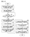
- FIG. 15 is a diagram showing a processing flow of the terminal device 1 according to the third exemplary embodiment of the present invention.
- the processing flow of the terminal device 1 according to the third exemplary embodiment will be described with reference to an example in which the user pays money using the terminal device 1 provided with an electronic money function using a non-contact reception function at the time of shopping.
- steps S 16 to S 20 in the processing flow of the terminal device 1 according to the third exemplary embodiment of the present invention it is the same as that of the terminal device 1 according to the first exemplary embodiment.
- steps S 16 to S 20 in the processing flow of the terminal device 1 according to the third exemplary embodiment of the present invention will be described.
- FIG. 16 is a diagram showing a display example of the display unit 4 of the terminal device 1 according to the third exemplary embodiment of the present invention.
- FIG. 16 shows a display example of the display unit 4 in a state in which the user has moved the photographing unit 6 provided in the terminal device 1 directly above the target mark 121 on a surface S of the opposed device 11 .
- the processing flow of the terminal device 1 of the third exemplary embodiment performs the process of steps S 1 to S 5 as in the first exemplary embodiment.
- the user moves the terminal device 1 until the target mark 121 reaches a predetermined position of a photographing region A 4 of the photographing unit 6 .
- the user moves the terminal device 1 to a position at which the target mark 121 stays at the center of the photographing unit 6 as shown in FIG. 16 .
- the user for example, performs an operation of setting the position to a base point position according to a user operation such as an operation of touching the display unit 4 .
- the position calculation unit 14 of the terminal device 1 receives an input of a signal for recognizing the base point position as a calculation reference from the display unit 4 .
- the position calculation unit 14 starts detection of the movement state of the terminal device 1 (step S 16 ).
- positions of the photographing unit 6 provided in the terminal device 1 and the target mark 121 become positions at which they relatively face each other.
- a positional relationship between the photographing unit 6 and the non-contact unit 2 in the terminal device 1 is physically known. Accordingly, the user physically moves the terminal device 1 so that the non-contact unit 2 at the current time reaches a position of the photographing unit 6 at the current time as indicated by an arrow R (an offset between the non-contact unit 2 and the photographing unit 6 ) in FIG. 16 . That is, if the user moves the terminal device 1 by a distance X 3 in the horizontal direction and a distance Y 3 in the vertical direction, the non-contact unit 2 and the target mark 121 are positioned to relatively face each other.
- the display unit 4 of the terminal device 1 instructs the user to move the terminal device 1 by the distance X 3 in the horizontal direction and the distance Y 3 in the vertical direction based on a calculation result of the position calculation unit 14 .
- the posture detection unit 7 which is an acceleration sensor for example, detects the acceleration in movement for alignment of the terminal device 1 by the user and outputs the detection result of the acceleration to the position calculation unit 14 (step S 17 ).
- the position calculation unit 14 receives an input of the detection result of the acceleration from the posture detection unit 7 .
- the position calculation unit 14 calculates the distance based on the detection result of the acceleration by integrating the acceleration twice (step S 18 ).
- the position calculation unit 14 outputs the calculation result to the display unit 4 (step S 19 ).
- the display unit 4 receives an input of the calculation result from the position calculation unit 14 .
- the display unit 4 indicates the movement direction of the terminal device 1 and its movement distance by numerical values and displays a movement instruction of the terminal device 1 for the user (step S 20 ).
- a program necessary for this display is stored in the storage unit 10 in advance.
- the display unit 4 may display and indicate the movement direction by an arrow in real time while the user moves the terminal device 1 .
- the position calculation unit 14 may read information in which movement data stored in the storage unit 10 is associated with instruction data such as audio data and output audio data associated with movement corresponding to a calculation result to a speaker of the display unit 4 or the like, and the display unit 4 may instruct the user to move the terminal device 1 by audio based on the audio data.
- step S 9 is performed as in the first exemplary embodiment.
- the processing flow of the terminal device 1 according to the third exemplary embodiment has been described above.
- the user can cause the non-contact unit 2 and the target mark 121 to face each other if the terminal device 1 is moved according to an instruction displayed on the display unit 4 .
- it is possible to perform alignment of the terminal device 1 and the opposed device 11 .
- some or all of the functions other than the non-contact reception function of the terminal device 1 may be temporarily stopped when the determination unit 3 determines that the user intends to use the non-contact reception function.
- the determination unit 3 determines that the user intends to use the non-contact reception function
- the reception of an operation input that is input from outside of the device (the terminal device 1 ) may be limited.
- a computer system may be provided inside the terminal devices according to the above-described exemplary embodiments of the present invention.
- a process of the above-described processing may be stored in a computer-readable recording medium 70 in the form of a program, and the above-described process may be performed when the computer reads and executes the program.
- the computer-readable recording medium 70 includes a magnetic disk, a magneto-optical disc, a CD-ROM, a DVD-ROM, a semiconductor memory, or the like.
- the computer program may be distributed to the computer through a communication line, and the computer receiving the distribution may execute the program.
- the above-described program may be used to implement some of the above-described functions.
- the above-described program may be a so-called differential file (differential program) capable of implementing the above-described functions in combination with a program already stored in the computer system.
- the present invention is applicable to a terminal device, an information processing method, and a program.
Landscapes
- Engineering & Computer Science (AREA)
- Computer Networks & Wireless Communication (AREA)
- Signal Processing (AREA)
- Human Computer Interaction (AREA)
- Environmental & Geological Engineering (AREA)
- Telephone Function (AREA)
- User Interface Of Digital Computer (AREA)
Abstract
Description
- Japanese Unexamined Patent Application, First Publication No. 2007-53424
[Patent Document 2] - Japanese Unexamined Patent Application, First Publication No. 2007-300579
[Patent Document 3] - Japanese Unexamined Patent Application, First Publication No. 2008-92304
-
- 1 Terminal device
- 2, 12 Non-contact unit
- 2 b Non-contact unit mark
- 3 Use intention determination unit
- 4 Display unit
- 5 Proximity detection unit
- 6 Photographing unit
- 7 Posture detection unit
- 8 Display correction unit
- 9 Image processing unit
- 10 Storage unit
- 11 Opposed device
- 13 Control unit
- 14 Position calculation unit
- 121 Target mark
- A1, A2, A3, A4 Photographing region
- o1 Center of photographing region A1
- o2 Center of
display unit 4 - o3 Center of image
- o4 Position of photographing
unit 6
Claims (13)
Applications Claiming Priority (3)
| Application Number | Priority Date | Filing Date | Title |
|---|---|---|---|
| JP2012226498 | 2012-10-12 | ||
| JP2012-226498 | 2012-10-12 | ||
| PCT/JP2013/077263 WO2014057912A1 (en) | 2012-10-12 | 2013-10-07 | Terminal device, information processing method and program |
Publications (2)
| Publication Number | Publication Date |
|---|---|
| US20150271310A1 US20150271310A1 (en) | 2015-09-24 |
| US9407750B2 true US9407750B2 (en) | 2016-08-02 |
Family
ID=50477379
Family Applications (1)
| Application Number | Title | Priority Date | Filing Date |
|---|---|---|---|
| US14/434,310 Expired - Fee Related US9407750B2 (en) | 2012-10-12 | 2013-10-07 | Terminal device, information processing method and program |
Country Status (5)
| Country | Link |
|---|---|
| US (1) | US9407750B2 (en) |
| EP (1) | EP2908506B1 (en) |
| JP (1) | JP6344238B2 (en) |
| CN (1) | CN104704799B (en) |
| WO (1) | WO2014057912A1 (en) |
Families Citing this family (2)
| Publication number | Priority date | Publication date | Assignee | Title |
|---|---|---|---|---|
| US10440263B2 (en) * | 2017-05-12 | 2019-10-08 | Microsoft Technology Licensing, Llc | Synchronized display on hinged multi-screen device |
| EP4131156A4 (en) * | 2020-03-31 | 2023-06-28 | Sony Group Corporation | Information processing device, information processing method, and information processing program |
Citations (13)
| Publication number | Priority date | Publication date | Assignee | Title |
|---|---|---|---|---|
| JP2002169645A (en) | 2000-12-01 | 2002-06-14 | Toshiba Corp | Mobile communication terminal |
| JP2003163739A (en) | 2001-11-27 | 2003-06-06 | Nec Corp | Security method and security system for portable telephone set |
| JP2005328130A (en) | 2004-05-12 | 2005-11-24 | Sony Ericsson Mobilecommunications Japan Inc | Wireless communication system, wireless communication terminal, and base station |
| JP2006345016A (en) | 2005-06-07 | 2006-12-21 | Nec Saitama Ltd | Portable telephone having non-contact ic card function, and control method thereof |
| JP2007053424A (en) | 2005-08-15 | 2007-03-01 | Nec Saitama Ltd | Apparatus and method for short-distance radio communication, and portable information processing terminal equipped therewith |
| JP2007300579A (en) | 2006-05-08 | 2007-11-15 | Sony Ericsson Mobilecommunications Japan Inc | Mobile terminal, contactless communication control method and program |
| WO2008039559A1 (en) | 2006-09-29 | 2008-04-03 | Sony Ericsson Mobile Communications Ab | Device and method for guiding a user to a communication position |
| JP2008092304A (en) | 2006-10-02 | 2008-04-17 | Matsushita Electric Ind Co Ltd | Mobile terminal device |
| EP2211480A1 (en) | 2009-01-26 | 2010-07-28 | Motorola, Inc. | Wireless communication device for providing at least one near field communication service |
| JP2011034196A (en) | 2009-07-30 | 2011-02-17 | Nec Casio Mobile Communications Ltd | Portable terminal device and program |
| JP2011166630A (en) | 2010-02-12 | 2011-08-25 | Kyocera Corp | Portable electronic device |
| WO2013040605A2 (en) | 2011-09-18 | 2013-03-21 | Google Inc. | One-click offline buying |
| US8634871B2 (en) * | 2010-02-12 | 2014-01-21 | Kyocera Corporation | Mobile electronic device |
Family Cites Families (1)
| Publication number | Priority date | Publication date | Assignee | Title |
|---|---|---|---|---|
| US8929810B2 (en) * | 2012-04-23 | 2015-01-06 | Qualcomm Incorporated | Methods and apparatus for improving NFC connection through device positioning |
-
2013
- 2013-10-07 EP EP13845980.5A patent/EP2908506B1/en not_active Not-in-force
- 2013-10-07 WO PCT/JP2013/077263 patent/WO2014057912A1/en not_active Ceased
- 2013-10-07 US US14/434,310 patent/US9407750B2/en not_active Expired - Fee Related
- 2013-10-07 JP JP2014540841A patent/JP6344238B2/en not_active Expired - Fee Related
- 2013-10-07 CN CN201380052891.9A patent/CN104704799B/en not_active Expired - Fee Related
Patent Citations (13)
| Publication number | Priority date | Publication date | Assignee | Title |
|---|---|---|---|---|
| JP2002169645A (en) | 2000-12-01 | 2002-06-14 | Toshiba Corp | Mobile communication terminal |
| JP2003163739A (en) | 2001-11-27 | 2003-06-06 | Nec Corp | Security method and security system for portable telephone set |
| JP2005328130A (en) | 2004-05-12 | 2005-11-24 | Sony Ericsson Mobilecommunications Japan Inc | Wireless communication system, wireless communication terminal, and base station |
| JP2006345016A (en) | 2005-06-07 | 2006-12-21 | Nec Saitama Ltd | Portable telephone having non-contact ic card function, and control method thereof |
| JP2007053424A (en) | 2005-08-15 | 2007-03-01 | Nec Saitama Ltd | Apparatus and method for short-distance radio communication, and portable information processing terminal equipped therewith |
| JP2007300579A (en) | 2006-05-08 | 2007-11-15 | Sony Ericsson Mobilecommunications Japan Inc | Mobile terminal, contactless communication control method and program |
| WO2008039559A1 (en) | 2006-09-29 | 2008-04-03 | Sony Ericsson Mobile Communications Ab | Device and method for guiding a user to a communication position |
| JP2008092304A (en) | 2006-10-02 | 2008-04-17 | Matsushita Electric Ind Co Ltd | Mobile terminal device |
| EP2211480A1 (en) | 2009-01-26 | 2010-07-28 | Motorola, Inc. | Wireless communication device for providing at least one near field communication service |
| JP2011034196A (en) | 2009-07-30 | 2011-02-17 | Nec Casio Mobile Communications Ltd | Portable terminal device and program |
| JP2011166630A (en) | 2010-02-12 | 2011-08-25 | Kyocera Corp | Portable electronic device |
| US8634871B2 (en) * | 2010-02-12 | 2014-01-21 | Kyocera Corporation | Mobile electronic device |
| WO2013040605A2 (en) | 2011-09-18 | 2013-03-21 | Google Inc. | One-click offline buying |
Non-Patent Citations (2)
| Title |
|---|
| Extended European Search Report for EP Application No. EP13845980.5 dated May 3, 2016. |
| International Search Report for PCT Application No. PCT/JP2013/077263 , mailed on Nov. 12, 2013. |
Also Published As
| Publication number | Publication date |
|---|---|
| EP2908506B1 (en) | 2018-04-18 |
| EP2908506A4 (en) | 2016-06-01 |
| EP2908506A1 (en) | 2015-08-19 |
| WO2014057912A1 (en) | 2014-04-17 |
| CN104704799B (en) | 2018-03-20 |
| JP6344238B2 (en) | 2018-06-20 |
| JPWO2014057912A1 (en) | 2016-09-05 |
| CN104704799A (en) | 2015-06-10 |
| US20150271310A1 (en) | 2015-09-24 |
Similar Documents
| Publication | Publication Date | Title |
|---|---|---|
| CN111543041B (en) | A method for selecting an analog card and a mobile device | |
| US11003753B2 (en) | Method for recognizing fingerprint, and electronic device and storage medium therefor | |
| US20110176705A1 (en) | Information processing device, information processing system and program | |
| CN104345972A (en) | Method, electronic device and computer readable medium for operating an electronic device | |
| US11836941B2 (en) | Package measuring apparatus, package accepting system, package measuring method, and non-transitory computer readable medium | |
| KR102603254B1 (en) | An electornic devid and a method for displaying web contents in augmented reality mode | |
| CN113012211A (en) | Image acquisition method, device, system, computer equipment and storage medium | |
| CN111538009A (en) | Radar point marking method and device | |
| WO2020145570A1 (en) | Electronic device, protective case for electronic device, and displaying method thereof | |
| US20140376050A1 (en) | Information terminal apparatus, method of controlling information terminal apparatus, and storage medium | |
| KR101994841B1 (en) | Providing information about welfare point store based on location and welfare point payment system and method thereof | |
| KR20160147340A (en) | Display apparatus and controlling method thereof | |
| KR20160101580A (en) | Method for controlling activation area of touch screen panel and electronic device thereof | |
| CN113205069B (en) | False license plate detection method, device and computer storage medium | |
| US9407750B2 (en) | Terminal device, information processing method and program | |
| CN105630239A (en) | Method and device for detecting operation | |
| US9412090B2 (en) | System, mobile communication terminal and method for providing information | |
| CN107705317A (en) | The control system of view-based access control model Tracking Recognition | |
| KR101830739B1 (en) | Touch panel, mobile terminal and wireless input apparatus | |
| US20160004379A1 (en) | Manipulation input device, portable information terminal, method for control of manipulation input device, and recording medium | |
| CN112052708B (en) | Object detection method, device and system | |
| EP3857923B1 (en) | Electronic device for detecting location of user and method thereof | |
| KR101677640B1 (en) | Apparatus for detecting lane and method thereof | |
| KR20180056983A (en) | Mobile terminal, server, payment systetm and method for payment based on identification code | |
| CN114207565A (en) | Electronic device comprising a display and a sensor |
Legal Events
| Date | Code | Title | Description |
|---|---|---|---|
| AS | Assignment |
Owner name: NEC CASIO MOBILE COMMUNICATIONS, LTD., JAPAN Free format text: ASSIGNMENT OF ASSIGNORS INTEREST;ASSIGNOR:KITATANI, KENICHI;REEL/FRAME:035574/0554 Effective date: 20150427 |
|
| AS | Assignment |
Owner name: NEC MOBILE COMMUNICATIONS, LTD., JAPAN Free format text: CHANGE OF NAME;ASSIGNOR:NEC CASIO MOBILE COMMUNICATIONS, LTD.;REEL/FRAME:035866/0495 Effective date: 20141002 |
|
| AS | Assignment |
Owner name: NEC CORPORATION, JAPAN Free format text: ASSIGNMENT OF ASSIGNORS INTEREST;ASSIGNOR:NEC MOBILE COMMUNICATIONS, LTD.;REEL/FRAME:036037/0476 Effective date: 20150618 |
|
| STCF | Information on status: patent grant |
Free format text: PATENTED CASE |
|
| FEPP | Fee payment procedure |
Free format text: MAINTENANCE FEE REMINDER MAILED (ORIGINAL EVENT CODE: REM.); ENTITY STATUS OF PATENT OWNER: LARGE ENTITY |
|
| LAPS | Lapse for failure to pay maintenance fees |
Free format text: PATENT EXPIRED FOR FAILURE TO PAY MAINTENANCE FEES (ORIGINAL EVENT CODE: EXP.); ENTITY STATUS OF PATENT OWNER: LARGE ENTITY |
|
| STCH | Information on status: patent discontinuation |
Free format text: PATENT EXPIRED DUE TO NONPAYMENT OF MAINTENANCE FEES UNDER 37 CFR 1.362 |
|
| FP | Lapsed due to failure to pay maintenance fee |
Effective date: 20200802 |