US9407411B2 - Control station apparatus, wireless communication system, allocation method and program - Google Patents
Control station apparatus, wireless communication system, allocation method and program Download PDFInfo
- Publication number
- US9407411B2 US9407411B2 US14/385,005 US201314385005A US9407411B2 US 9407411 B2 US9407411 B2 US 9407411B2 US 201314385005 A US201314385005 A US 201314385005A US 9407411 B2 US9407411 B2 US 9407411B2
- Authority
- US
- United States
- Prior art keywords
- station apparatus
- mobile station
- reference signal
- parameter
- parameter set
- Prior art date
- Legal status (The legal status is an assumption and is not a legal conclusion. Google has not performed a legal analysis and makes no representation as to the accuracy of the status listed.)
- Active, expires
Links
- 238000004891 communication Methods 0.000 title claims description 20
- 238000000034 method Methods 0.000 title claims description 17
- 125000004122 cyclic group Chemical group 0.000 claims abstract description 25
- 238000001514 detection method Methods 0.000 description 11
- 108010076504 Protein Sorting Signals Proteins 0.000 description 7
- 230000007274 generation of a signal involved in cell-cell signaling Effects 0.000 description 7
- 238000006243 chemical reaction Methods 0.000 description 4
- 238000010586 diagram Methods 0.000 description 4
- NRNCYVBFPDDJNE-UHFFFAOYSA-N pemoline Chemical compound O1C(N)=NC(=O)C1C1=CC=CC=C1 NRNCYVBFPDDJNE-UHFFFAOYSA-N 0.000 description 4
- 238000012552 review Methods 0.000 description 4
- 230000006870 function Effects 0.000 description 3
- 238000003780 insertion Methods 0.000 description 3
- 230000037431 insertion Effects 0.000 description 3
- 238000010295 mobile communication Methods 0.000 description 2
- 238000013459 approach Methods 0.000 description 1
- 230000005540 biological transmission Effects 0.000 description 1
- 238000012937 correction Methods 0.000 description 1
- 238000013461 design Methods 0.000 description 1
- 230000007774 longterm Effects 0.000 description 1
- 238000012986 modification Methods 0.000 description 1
- 230000004048 modification Effects 0.000 description 1
- 230000002093 peripheral effect Effects 0.000 description 1
- 230000010363 phase shift Effects 0.000 description 1
- 239000004065 semiconductor Substances 0.000 description 1
Images


Classifications
-
- H—ELECTRICITY
- H04—ELECTRIC COMMUNICATION TECHNIQUE
- H04L—TRANSMISSION OF DIGITAL INFORMATION, e.g. TELEGRAPHIC COMMUNICATION
- H04L5/00—Arrangements affording multiple use of the transmission path
- H04L5/003—Arrangements for allocating sub-channels of the transmission path
- H04L5/0048—Allocation of pilot signals, i.e. of signals known to the receiver
-
- H—ELECTRICITY
- H04—ELECTRIC COMMUNICATION TECHNIQUE
- H04L—TRANSMISSION OF DIGITAL INFORMATION, e.g. TELEGRAPHIC COMMUNICATION
- H04L27/00—Modulated-carrier systems
- H04L27/26—Systems using multi-frequency codes
- H04L27/2601—Multicarrier modulation systems
- H04L27/2602—Signal structure
- H04L27/261—Details of reference signals
-
- H—ELECTRICITY
- H04—ELECTRIC COMMUNICATION TECHNIQUE
- H04L—TRANSMISSION OF DIGITAL INFORMATION, e.g. TELEGRAPHIC COMMUNICATION
- H04L5/00—Arrangements affording multiple use of the transmission path
- H04L5/0001—Arrangements for dividing the transmission path
- H04L5/0014—Three-dimensional division
- H04L5/0016—Time-frequency-code
-
- H—ELECTRICITY
- H04—ELECTRIC COMMUNICATION TECHNIQUE
- H04L—TRANSMISSION OF DIGITAL INFORMATION, e.g. TELEGRAPHIC COMMUNICATION
- H04L5/00—Arrangements affording multiple use of the transmission path
- H04L5/003—Arrangements for allocating sub-channels of the transmission path
- H04L5/0032—Distributed allocation, i.e. involving a plurality of allocating devices, each making partial allocation
- H04L5/0035—Resource allocation in a cooperative multipoint environment
-
- H—ELECTRICITY
- H04—ELECTRIC COMMUNICATION TECHNIQUE
- H04L—TRANSMISSION OF DIGITAL INFORMATION, e.g. TELEGRAPHIC COMMUNICATION
- H04L5/00—Arrangements affording multiple use of the transmission path
- H04L5/003—Arrangements for allocating sub-channels of the transmission path
- H04L5/0048—Allocation of pilot signals, i.e. of signals known to the receiver
- H04L5/0051—Allocation of pilot signals, i.e. of signals known to the receiver of dedicated pilots, i.e. pilots destined for a single user or terminal
-
- H—ELECTRICITY
- H04—ELECTRIC COMMUNICATION TECHNIQUE
- H04L—TRANSMISSION OF DIGITAL INFORMATION, e.g. TELEGRAPHIC COMMUNICATION
- H04L5/00—Arrangements affording multiple use of the transmission path
- H04L5/003—Arrangements for allocating sub-channels of the transmission path
- H04L5/0053—Allocation of signaling, i.e. of overhead other than pilot signals
-
- H—ELECTRICITY
- H04—ELECTRIC COMMUNICATION TECHNIQUE
- H04L—TRANSMISSION OF DIGITAL INFORMATION, e.g. TELEGRAPHIC COMMUNICATION
- H04L5/00—Arrangements affording multiple use of the transmission path
- H04L5/0091—Signaling for the administration of the divided path
Definitions
- the present invention relates to a control station apparatus, a wireless communication system, an allocation method, and a program.
- LTE Long Term Evolution
- LTE-A LTE Advanced
- a heterogeneous network to install a macro base station (enhanced node B: eNB) that covers a relatively wide range
- an LPN low power node, radio remote head: RRH
- a macro base station (may be referred to as a macro area)
- RRH radio remote head
- NPL 1 a reference signal parameter unique to a mobile station apparatus
- NPL 1 3GPP R1-120882
- NPL 1 Although independent configuration of a sequence of a reference signal unique to a mobile station apparatus is mentioned, there is no description on a specific method and there is a problem that a method of actually configuring only with NPL 1 is difficult.
- the present invention has made in view of such situation, and it is an object thereof to provide means of configuring a reference signal unique to a mobile station apparatus.
- a control station apparatus notifying a first mobile station apparatus of a parameter group generating a reference signal
- the control station apparatus including: an RRC layer to configure a parameter set including a plurality of parameter groups generating the reference signal; and a physical layer to select one of the parameter groups to notify the mobile station apparatus.
- the parameter set is configured with a plurality of parameter groups that respectively configure a sequence number and a cyclic shift hopping pattern of the reference signal and includes a parameter group generating a reference signal the same as in a second mobile station apparatus different from the first mobile station apparatus.
- the parameter set includes an initial value to configure a cyclic shift hopping pattern the same as in the second mobile station apparatus and, in a case that communication occurs at the same time of a legacy (conventional) mobile station apparatus, notifies the first mobile station apparatus of that.
- the parameter set includes a parameter generating identical reference signal and cyclic shift hopping pattern in a plurality of cooperating sending and receiving points.
- the parameter set is configured only with a parameter group that determines a plurality of a sequence number and a cyclic shift hopping pattern is determined with a virtual cell ID to determine a sequence number of the reference signal.
- the parameter set includes parameter groups to configure a sequence number of a reference signal the same as in the second mobile station apparatus.
- the present invention is a wireless communication system, including a control station apparatus notifying a first mobile station apparatus of a parameter group generating a reference signal and a mobile station apparatus, in which the control station apparatus includes an RRC layer to configure a parameter set having a plurality of parameter groups generating a reference signal, a physical layer to select one of the parameter groups and notify the first mobile station apparatus, the mobile station apparatus includes the first mobile station apparatus and a second mobile station apparatus different from the first mobile station apparatus, and the parameter set is configured with a plurality of parameter groups that respectively configure a sequence number and a cyclic shift hopping pattern of the reference signal and includes parameter groups generating a reference signal same as the second mobile station apparatus different from the first mobile station apparatus.
- a control method in a control station apparatus that notifies a first mobile station apparatus of a parameter group generating a reference signal, including the steps of: configuring a parameter set including a plurality of parameter groups generating the reference signal in an RRC layer; and selecting one of the parameter groups in a physical layer to notify a mobile station apparatus.
- the present invention may also be a program causing a computer to execute the control method described above, and may also be a computer-readable recording medium to record the program.
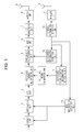
- FIG. 1 is a functional block diagram illustrating one configuration example of a mobile station apparatus in a first embodiment of the present invention.
- FIG. 2 is a diagram illustrating a subframe, which is a smallest unit of a resource of a mobile station apparatus.
- FIG. 3 is a functional block diagram illustrating a configuration example of a station apparatus.
- FIG. 1 is a functional block diagram illustrating one configuration example of a mobile station apparatus in the present embodiment.
- control information received in an antenna 10 is subject to process of converting a wireless signal to a baseband signal, such as analog to digital (A/D) conversion and down conversion, by a wireless unit 11 , and the control information is detected by a control information detection unit 12 .
- the detected control information is inputted to an allocation information detection unit 13 , and an allocation frequency location of the frequency resource is detected to be inputted to a frequency allocation unit 5 .
- MCS modulation and coding schemes
- Error correction coding is carried out based on the notified coding rate in the coding unit 1 , and modulation such as quaternary phase shift keying (QPSK) and 16 quadrature amplitude modulation (QAM) is carried out in the modulation unit 2 , and time frequency transform is carried out by discrete Fourier transform (DFT) in a DFT unit 3 .
- a demodulation reference signal (DMRS) generated in the reference signal generation unit 16 is multiplexed to be inputted to the frequency allocation unit 5 .
- DMRS demodulation reference signal
- a transmit signal is allocated in a frequency domain based on the allocation information in the frequency allocation unit 5 to be transformed to a time signal using inverse fast Fourier transform (IFFT) in an IFFT unit 6 , and insertion of a cyclic prefix (CP), which is process of copying the back of a time waveform to the front, is carried out in a CP insertion unit 7 , and process to make a wireless signal, such as D/A conversion and up conversion, is carried out by a wireless unit 8 to be sent from an antenna 9 .
- IFFT inverse fast Fourier transform
- CP cyclic prefix
- FIG. 2 illustrates a subframe, which is a smallest unit of a resource of a mobile station apparatus.
- a subframe composed of 1 msec is configured with 14 symbols of DFT blocks, and two slots are defined for respective 7 symbols.
- 21 and 22 to be time multiplexed in the center of the respective slots are DMRS, and two of them are defined in the subframe, that is, one in each slot.
- the DMRS is generated from three parameters of a sequence group number, sequence group hopping, and a cyclic shift hopping pattern of the Zadoff-Chu sequence. It is possible to select the Zadoff-Chu sequence from 30 types of sequence having fixed amplitude and excellent in auto-correlation and cross-correlation, and each sequence number has different complex amplitude of a frequency domain.
- the sequence group hopping represents process to select a sequence different for each slot, and it is possible to determine which pattern to alter the Zadoff-Chu sequence. It is possible to select either to have the Zadoff-Chu sequence different for each slot or to have the same Zadoff-Chu sequence.
- the cyclic shift represents to further give phase rotation at a fixed interval for each subcarrier in a frequency domain to the Zadoff-Chu sequence in each slot, and one of eight types of a phase rotation amount is applicable.
- the cyclic shift hopping is to give different phase rotation amounts among the slots to the Zadoff-Chu sequence in the respective slots, and thus it is possible to achieve randomization of the interference between cells.
- a parameter to determine respective phase rotation amounts in the first slot and the second slot when the cyclic shift hopping is applied is defined as a cyclic shift hopping parameter.
- a reference signal is generated.
- a Zadoff-Chu sequence number u ( f gh ( n S )+ f SS )mod 30 (1)
- f gh (n S ) is a formula defined in accordance with whether or not to perform sequence group hopping expressed in Formula (2), and is given as follows.
- n S denotes a slot number (0 or 1)
- c(x) a random number generator based on an M sequence disclosed in the specification (TS36.211 v10.4.0, Section 7.2) is used, and c init that represents a connection of an initial value thereof is determined by the following formula.
- Formula (3) uses N ID BSI inputted from the reference signal sequence information detection unit 14 .
- f SS is defined as a different value depending on a control channel (PUCCH) as Formula (4) or a shared channel (PUSCH).
- PUCCH control channel
- PUSCH shared channel
- Formula (4) expresses a parameter called f SS in a case of a control channel, and Formula (5) is f SS of a shared channel subject to the present embodiment.
- Formula (5) is f SS of a shared channel subject to the present embodiment.
- n cs, ⁇ ( n DMRS (1) +n DMRS, ⁇ (2) +n PN ( n S ))mod 12 (6)
- n DMRS (1) is a value configured in a higher layer (disclosed in TS36.211 v10.4.0, Table 5.5.2.1.1-2), n DMRS (1) is a value notified by the control channel in a down link (disclosed in TS36.211 v10.4.0, Table 5.5.2.1.1-1), and n PN (n S ) is a parameter to change the cyclic shift amount among the slots defined in Formula (7).
- N symb UL is a number of DFT blocks (7 in the present embodiment) contained in one slot, and for c(x), a random number generator based on the M sequence disclosed in the specification (TS36.211 v10.4.0, Section 7.2) is used and an initial value thereof is c init CSH .
- the parameters of ⁇ N ID BSI , ⁇ SS BSI , c init CSH ⁇ are independently configuring the parameters of ⁇ N ID BSI , ⁇ SS BSI , c init CSH ⁇ as values unique to the mobile station, it is possible to independently configure a sequence number and cyclic shift hopping.
- the parameters to determine the Zadoff-Chu sequence number are N ID BSI and ⁇ SS BSI
- the parameter to determine the cyclic shift hopping pattern is c init CSH .
- FIG. 3 illustrates a configuration example of a base station apparatus B.
- a radio resource control (RRC) layer controlling a data link layer (layer 2) and belonging to a network layer (layer 3) unless otherwise specified is indicated herein
- the present invention described herein includes as long as a layer is higher than a physical layer (layer 1) (a layer achieving a protocol contained in the data link layer and the network layer))
- a parameter set related to ⁇ N ID BSI , ⁇ SS BSI , c init CSH ⁇ (a (plurality of sets of ⁇ N ID BSI , ⁇ SS BSI , c init CSH ⁇ ) is specified in a parameter set configuration unit 31 in advance and any one set is selected in a parameter set selection unit 32 in a lower physical layer.
- the physical layer falls under the layer 1 of an open systems interconnection (OSI) basic reference model that carries out communication using a physical wireless channel and is a layer that carries out sending and receiving of a wireless signal.
- OSI open systems interconnection
- One of parameter sets selected in such a manner (herein, defined as a parameter group) is made as a down control signal, such as downlink control information (DCI), in a control information generation unit 33 , and the control signal is converted to a wireless signal in a wireless unit 34 to be sent from an antenna 35 to a mobile station apparatus.
- DCI downlink control information
- any one of parameter groups is defined.
- Table 1 indicates a specific example of parameter set in the RRC.
- Table 1 indicates a specific example of parameter set in the RRC.
- four types of parameter set are prepared in advance in the RRC and it is possible to notify in two bits.
- ⁇ N r10 , ⁇ r10 , c r10 ⁇ of Index 3 includes those having same configuration as a reference signal until the conventional Rel-10, and by configuring in such a manner, it is possible to orthogonalize the DMRS even when a mobile station apparatus of conventional Rel-10 is present in an area.
- the mobile station apparatus of Rel-10 or earlier refers to a mobile station apparatus to which a reference signal automatically determined from each macro base station or a physical cell ID of the LPN is applied, that is, to which the parameter group is not notified and may be referred to as a legacy mobile station apparatus. Therefore, the sequence is basically different from a case of configuring a reference signal unique to a mobile station apparatus subject to the present invention.
- all parameters are configured to be same as a legacy mobile station apparatus here, it is possible to specifically orthogonalize with an orthogonal code called as an orthogonal cover code (OCC) even when a legacy mobile station apparatus is present as long as any one, particularly a parameter c r10 having an identical cyclic shift pattern, is same.
- OCC orthogonal cover code
- ⁇ SS BSI , c init CSH ⁇ relative to each value of N ID BSI in the RRC may also be made as a parameter set separately.
- Table 2 indicates a parameter group in common with cooperation areas and control station apparatuses included in a parameter set.
- ⁇ N c , ⁇ c , c c ⁇ indicated in Index 0 are the example characterized by the present invention, and this configures a same parameter in a plurality of base stations in a case of cooperation communication.
- This is an example where same sequence number and cyclic shift hopping are applicable to all macro base stations and LPN (may also be referred to as a sending and receiving point, referred to as a control station apparatus herein) in the cooperation communication area.
- a parameter to be same as a legacy mobile station apparatus in any one of parameter set it becomes possible to orthogonalize a reference signal with a legacy mobile station apparatus by the OCC. It is also included in the present invention to contain at least a parameter configuring an identical reference signal sequence in an area for cooperation communication in a parameter set. Further, when only intended to orthogonalization, it is possible to achieve making c init CSH only identical among legacy mobile station apparatuses, or areas to carry out cooperation communication, or cooperating base stations, so that such case is also included in the present invention.
- a reference signal of Rel-10 or earlier and a reference signal unique to a mobile station apparatus is switched with one bit.
- an arbitrary reference signal sequence may be achieved only with N ID BS . This is indicated in Table 3.
- a case of generating a reference signal of a sequence number same as a legacy mobile station apparatus is indicated.
- a second embodiment indicates an example of using a virtual cell ID only.
- the difference from the first embodiment is in a point of determining cyclic shift hopping.
- an initial value of c init CSH unique to a mobile station apparatus when determining a phase rotation amount of cyclic shift hopping in Formula (7) here it is determined from a virtual cell ID as Formula (8).
- a parameter set is defined to allow configuration of an identical parameter among areas for cooperation communication or macro base stations for cooperation communication and LPN and one from them is dynamically notified to a mobile station apparatus.
- a program to achieve all or part of the functions of the respective mobile station apparatuses and the control station apparatuses in the respective embodiments above described may also be recorded in a computer-readable recording medium and the program that is recorded in the recording medium is read and executed by a computer system, thereby achieving a mobile station apparatus and a station apparatus.
- the “computer system” in this context includes OS and hardware, such as a peripheral device.
- the “computer-readable recording medium” refers to a portable medium, such as a flexible disk, a magnetooptical disk, a ROM, and a CD-ROM, and a storage apparatus, such as a hard disk built in a computer system. Further, the “computer-readable recording medium” also includes those dynamically holding a program for a short period of time, such as a communication line in a case of sending a program via a communication line such as a network like the internet and a telephone line, and those holding a program for a certain period of time, such as a volatile memory in a computer system to be a server and a client in that case.
- the above program may also be to achieve a part of the functions described before and further may also be one that is capable of achieving the functions described above in combination with a program already recorded in a computer system.
- all or part of the respective mobile station apparatus A and base station apparatus B in the respective embodiments described above may also be achieved as an LSI, which is typically an integrated circuit.
- the respective functional blocks of the mobile station apparatus A and the base station apparatus B may also be made into a chip individually and all or part may also be integrated and made into a chip.
- a part may also be made into a chip and another part may also be achieved as software.
- the approach to make an integrated circuit is not limited to an LSI but may also be achieved by a dedicated circuit or a general processor.
- a technique to make an integrated circuit to substitute the LSI appears due to an advance in the semiconductor technique, it is also possible to use an integrated circuit by the technique.
- the present invention is not limited to this.
Abstract
Description
[Math 1]
u=(f gh(n S)+f SS)mod 30 (1)
[Math 4]
f SS PUCCH =N ID cell mod 30 (4)
[Math 5]
f SS PUSCH=(f SS PUCCH+ΔSS BSI)mod 30 (5)
[Math 6]
n cs,λ=(n DMRS (1) +n DMRS,λ (2) +n PN(n S))mod 12 (6)
| TABLE 1 | |||||
| Index | NID BSI | ΔSS BSI | cinit CSH | ||
| 0 | N1 | Δ1 | c1 | ||
| 1 | N2 | Δ2 | c2 | ||
| 2 | N3 | Δ3 | c3 | ||
| 3 | Nr10 | Δr10 | cr10 | ||
| TABLE 2 | |||||
| Index | NID BSI | ΔSS BSI | cinit CSH | ||
| 0 | Nc | Δc | c1 | ||
| 1 | N2 | Δ2 | c2 | ||
| 2 | N3 | Δ3 | c3 | ||
| 3 | Nr10 | Δr10 | cr10 | ||
| TABLE 3 | ||
| Index | NID BSI | cinit CSH |
| 0 | N1 | c1 |
| 1 | N2 | c2 |
| 2 | N3 | c3 |
| 3 | Nr10 | cr10 |
| TABLE 4 | ||
| Index | NID BSI | ΔSS BSI |
| 0 | N1 | Δ1 |
| 1 | N2 | Δ2 |
| 2 | N3 | Δ3 |
| 3 | Nr10 | Δr10 |
-
- A mobile station apparatus
- 1 coding unit
- 2 modulation unit
- 3 DFT unit
- 4 reference signal multiplexing unit
- 5 frequency allocation unit
- 6 IFFT unit
- 7 CP insertion unit
- 8 wireless unit
- 9 antenna
- 10 antenna
- 11 wireless unit
- 12 control information detection unit
- 13 allocation information detection unit
- 14 reference signal sequence information detection unit
- 15 MCS information detection unit
- 16 reference signal generation unit
- B base station apparatus
- 31 parameter set configuration unit
- 32 parameter set selection unit
- 33 control signal generation unit
- 34 wireless unit
- 35 antenna
Claims (8)
Applications Claiming Priority (3)
| Application Number | Priority Date | Filing Date | Title |
|---|---|---|---|
| JP2012057929A JP5815442B2 (en) | 2012-03-14 | 2012-03-14 | Control station apparatus, radio communication system, allocation method and program |
| JP2012-057929 | 2012-03-14 | ||
| PCT/JP2013/055786 WO2013137034A1 (en) | 2012-03-14 | 2013-03-04 | Control station apparatus, wireless communication system, allocation method and program |
Publications (2)
| Publication Number | Publication Date |
|---|---|
| US20150063238A1 US20150063238A1 (en) | 2015-03-05 |
| US9407411B2 true US9407411B2 (en) | 2016-08-02 |
Family
ID=49160947
Family Applications (1)
| Application Number | Title | Priority Date | Filing Date |
|---|---|---|---|
| US14/385,005 Active 2033-05-12 US9407411B2 (en) | 2012-03-14 | 2013-03-04 | Control station apparatus, wireless communication system, allocation method and program |
Country Status (3)
| Country | Link |
|---|---|
| US (1) | US9407411B2 (en) |
| JP (1) | JP5815442B2 (en) |
| WO (1) | WO2013137034A1 (en) |
Families Citing this family (2)
| Publication number | Priority date | Publication date | Assignee | Title |
|---|---|---|---|---|
| KR102317044B1 (en) | 2014-07-16 | 2021-10-25 | 엘지전자 주식회사 | Method and device for estimating channel in wireless communication system |
| WO2017115651A1 (en) * | 2015-12-31 | 2017-07-06 | Sharp Kabushiki Kaisha | Systems and methods for configuring rrc prameters |
Citations (8)
| Publication number | Priority date | Publication date | Assignee | Title |
|---|---|---|---|---|
| US20120314743A1 (en) * | 2010-02-23 | 2012-12-13 | Pantech Co., Ltd. | Apparatus and method for transmitting a reference signal in a wireless communication system |
| US20130148592A1 (en) * | 2010-02-12 | 2013-06-13 | Lg Electronics Inc. | Data transmission method and device in wireless communication system |
| US20140161093A1 (en) * | 2011-08-05 | 2014-06-12 | Panasonic Corporation | Terminal, base station, transmission method and reception method |
| US20140247799A1 (en) * | 2011-10-04 | 2014-09-04 | Sharp Kabushiki Kaisha | Mobile station apparatus, base station apparatus, wireless communication method, and integrated circuit |
| US20140301345A1 (en) * | 2011-11-17 | 2014-10-09 | Lg Electronics Inc. | Method for receiving uplink signal, base station, method for transmitting uplink signal and user equipment |
| US8917618B2 (en) * | 2012-01-27 | 2014-12-23 | Intel Corporation | Uplink coordinated multi-point |
| US20150043465A1 (en) * | 2012-03-09 | 2015-02-12 | Sharp Kabushiki Kaisha | Base station, terminal, communication method, and integrated circuit |
| US20150146512A1 (en) * | 2010-05-03 | 2015-05-28 | Pantech Co., Ltd. | Apparatus and method for transmitting and receiving of cyclic shift parameter for supporting orthogonality in mimo environment |
Family Cites Families (1)
| Publication number | Priority date | Publication date | Assignee | Title |
|---|---|---|---|---|
| JP5538692B2 (en) * | 2008-08-08 | 2014-07-02 | キヤノン株式会社 | COMMUNICATION DEVICE, COMMUNICATION DEVICE CONTROL METHOD, COMPUTER PROGRAM |
-
2012
- 2012-03-14 JP JP2012057929A patent/JP5815442B2/en active Active
-
2013
- 2013-03-04 WO PCT/JP2013/055786 patent/WO2013137034A1/en active Application Filing
- 2013-03-04 US US14/385,005 patent/US9407411B2/en active Active
Patent Citations (8)
| Publication number | Priority date | Publication date | Assignee | Title |
|---|---|---|---|---|
| US20130148592A1 (en) * | 2010-02-12 | 2013-06-13 | Lg Electronics Inc. | Data transmission method and device in wireless communication system |
| US20120314743A1 (en) * | 2010-02-23 | 2012-12-13 | Pantech Co., Ltd. | Apparatus and method for transmitting a reference signal in a wireless communication system |
| US20150146512A1 (en) * | 2010-05-03 | 2015-05-28 | Pantech Co., Ltd. | Apparatus and method for transmitting and receiving of cyclic shift parameter for supporting orthogonality in mimo environment |
| US20140161093A1 (en) * | 2011-08-05 | 2014-06-12 | Panasonic Corporation | Terminal, base station, transmission method and reception method |
| US20140247799A1 (en) * | 2011-10-04 | 2014-09-04 | Sharp Kabushiki Kaisha | Mobile station apparatus, base station apparatus, wireless communication method, and integrated circuit |
| US20140301345A1 (en) * | 2011-11-17 | 2014-10-09 | Lg Electronics Inc. | Method for receiving uplink signal, base station, method for transmitting uplink signal and user equipment |
| US8917618B2 (en) * | 2012-01-27 | 2014-12-23 | Intel Corporation | Uplink coordinated multi-point |
| US20150043465A1 (en) * | 2012-03-09 | 2015-02-12 | Sharp Kabushiki Kaisha | Base station, terminal, communication method, and integrated circuit |
Non-Patent Citations (1)
| Title |
|---|
| 3GPP TSG RAN WG1 Meeting #68, R1-120882, Ericsson, ST-Ericsson, Agenda Item: 7.5.6.1.1, "Details on UL DMRS", Feb. 10-10, 2012. |
Also Published As
| Publication number | Publication date |
|---|---|
| WO2013137034A1 (en) | 2013-09-19 |
| JP5815442B2 (en) | 2015-11-17 |
| JP2013192112A (en) | 2013-09-26 |
| US20150063238A1 (en) | 2015-03-05 |
Similar Documents
| Publication | Publication Date | Title |
|---|---|---|
| AU2018215316B2 (en) | Base station apparatus, terminal apparatus, communication method, and integrated circuit | |
| US9848410B2 (en) | Demodulation reference signal mapping according to comb configuration | |
| US9794918B2 (en) | Method for transmitting demodulation reference signals in wireless communication system and terminal using same | |
| CN110214466B (en) | Base station device, terminal device, communication method, and integrated circuit | |
| JP5856810B2 (en) | Base station apparatus, mobile station apparatus, radio communication method, radio communication system, and integrated circuit | |
| JP6076044B2 (en) | Wireless communication method, wireless communication system, wireless base station, and user terminal | |
| EP2495905B1 (en) | Wireless communication system, base station device, mobile station device, wireless communication method, and integrated circuit | |
| CN110050452B (en) | Base station device, terminal device, communication method, and integrated circuit | |
| EP3493621B1 (en) | Terminal device, communication method and integrated circuit | |
| EP2903374A1 (en) | Terminal, communication method, and integrated circuit | |
| WO2013141114A1 (en) | Wireless base station device, user terminal, wireless communications system, and wireless communications method | |
| WO2015111325A1 (en) | User device, base-station device, integrated circuit, and communication method | |
| JP5432210B2 (en) | User terminal, radio base station, downlink control channel receiving method, and mobile communication system | |
| EP3635904B1 (en) | Providing information on a control channel | |
| JP5893999B2 (en) | Wireless communication system, base station apparatus, user terminal, and wireless communication method | |
| JP2019047375A (en) | Terminal device, base station device and communication method | |
| WO2015111323A1 (en) | User device, base-station device, integrated circuit, and communication method | |
| CN104662979A (en) | Terminal, base station, wireless communication method, and integrated circuit | |
| WO2016125580A1 (en) | Terminal device, base station device, integrated circuit, and communication method | |
| US9407411B2 (en) | Control station apparatus, wireless communication system, allocation method and program | |
| JP6034946B2 (en) | Base station apparatus, mobile station apparatus, radio communication method, radio communication system, and integrated circuit | |
| US20200344748A1 (en) | Pucch transmission method, terminal and network-side device | |
| KR102457905B1 (en) | Method and apparatus for transmitting and receiving uplink control information in unlicensed spectrum | |
| WO2016125584A1 (en) | Terminal device, base station device, integrated circuit, and communication method |
Legal Events
| Date | Code | Title | Description |
|---|---|---|---|
| AS | Assignment |
Owner name: SHARP KABUSHIKI KAISHA, JAPAN Free format text: ASSIGNMENT OF ASSIGNORS INTEREST;ASSIGNORS:YOKOMAKURA, KAZUNARI;TAKAHASHI, HIROKI;GOTO, JUNGO;AND OTHERS;REEL/FRAME:033742/0394 Effective date: 20140825 |
|
| STCF | Information on status: patent grant |
Free format text: PATENTED CASE |
|
| FEPP | Fee payment procedure |
Free format text: PAYOR NUMBER ASSIGNED (ORIGINAL EVENT CODE: ASPN); ENTITY STATUS OF PATENT OWNER: LARGE ENTITY |
|
| MAFP | Maintenance fee payment |
Free format text: PAYMENT OF MAINTENANCE FEE, 4TH YEAR, LARGE ENTITY (ORIGINAL EVENT CODE: M1551); ENTITY STATUS OF PATENT OWNER: LARGE ENTITY Year of fee payment: 4 |
|
| MAFP | Maintenance fee payment |
Free format text: PAYMENT OF MAINTENANCE FEE, 8TH YEAR, LARGE ENTITY (ORIGINAL EVENT CODE: M1552); ENTITY STATUS OF PATENT OWNER: LARGE ENTITY Year of fee payment: 8 |