US9407074B2 - Mount assembly - Google Patents

Mount assembly Download PDF

Info

Publication number
US9407074B2
US9407074B2 US13/486,667 US201213486667A US9407074B2 US 9407074 B2 US9407074 B2 US 9407074B2 US 201213486667 A US201213486667 A US 201213486667A US 9407074 B2 US9407074 B2 US 9407074B2
Authority
US
United States
Prior art keywords
collar
wall
arm
electronics
housing
Prior art date
Legal status (The legal status is an assumption and is not a legal conclusion. Google has not performed a legal analysis and makes no representation as to the accuracy of the status listed.)
Active, expires
Application number
US13/486,667
Other versions
US20130319752A1 (en
Inventor
William Cowles
Wendy Feldstein
George Feldstein
Thomas Mans
Current Assignee (The listed assignees may be inaccurate. Google has not performed a legal analysis and makes no representation or warranty as to the accuracy of the list.)
Crestron Electronics Inc
Original Assignee
Crestron Electronics Inc
Priority date (The priority date is an assumption and is not a legal conclusion. Google has not performed a legal analysis and makes no representation as to the accuracy of the date listed.)
Filing date
Publication date
Application filed by Crestron Electronics Inc filed Critical Crestron Electronics Inc
Priority to US13/486,667 priority Critical patent/US9407074B2/en
Assigned to CRESTRON ELECTRONICS INC. reassignment CRESTRON ELECTRONICS INC. ASSIGNMENT OF ASSIGNORS INTEREST (SEE DOCUMENT FOR DETAILS). Assignors: FELDSTEIN, WENDY, COWLES, WILLIAM, FELDSTEIN, GEORGE, MANN, THOMAS
Publication of US20130319752A1 publication Critical patent/US20130319752A1/en
Application granted granted Critical
Publication of US9407074B2 publication Critical patent/US9407074B2/en
Active legal-status Critical Current
Adjusted expiration legal-status Critical

Links

Images

Classifications

    • HELECTRICITY
    • H02GENERATION; CONVERSION OR DISTRIBUTION OF ELECTRIC POWER
    • H02GINSTALLATION OF ELECTRIC CABLES OR LINES, OR OF COMBINED OPTICAL AND ELECTRIC CABLES OR LINES
    • H02G3/00Installations of electric cables or lines or protective tubing therefor in or on buildings, equivalent structures or vehicles
    • H02G3/02Details
    • H02G3/08Distribution boxes; Connection or junction boxes
    • H02G3/12Distribution boxes; Connection or junction boxes for flush mounting
    • H02G3/123Distribution boxes; Connection or junction boxes for flush mounting in thin walls
    • FMECHANICAL ENGINEERING; LIGHTING; HEATING; WEAPONS; BLASTING
    • F21LIGHTING
    • F21VFUNCTIONAL FEATURES OR DETAILS OF LIGHTING DEVICES OR SYSTEMS THEREOF; STRUCTURAL COMBINATIONS OF LIGHTING DEVICES WITH OTHER ARTICLES, NOT OTHERWISE PROVIDED FOR
    • F21V21/00Supporting, suspending, or attaching arrangements for lighting devices; Hand grips
    • F21V21/02Wall, ceiling, or floor bases; Fixing pendants or arms to the bases
    • F21V21/04Recessed bases
    • HELECTRICITY
    • H02GENERATION; CONVERSION OR DISTRIBUTION OF ELECTRIC POWER
    • H02GINSTALLATION OF ELECTRIC CABLES OR LINES, OR OF COMBINED OPTICAL AND ELECTRIC CABLES OR LINES
    • H02G3/00Installations of electric cables or lines or protective tubing therefor in or on buildings, equivalent structures or vehicles
    • H02G3/02Details
    • H02G3/08Distribution boxes; Connection or junction boxes
    • H02G3/18Distribution boxes; Connection or junction boxes providing line outlets
    • H02G3/20Ceiling roses or other lighting sets
    • HELECTRICITY
    • H04ELECTRIC COMMUNICATION TECHNIQUE
    • H04RLOUDSPEAKERS, MICROPHONES, GRAMOPHONE PICK-UPS OR LIKE ACOUSTIC ELECTROMECHANICAL TRANSDUCERS; DEAF-AID SETS; PUBLIC ADDRESS SYSTEMS
    • H04R2201/00Details of transducers, loudspeakers or microphones covered by H04R1/00 but not provided for in any of its subgroups
    • H04R2201/02Details casings, cabinets or mounting therein for transducers covered by H04R1/02 but not provided for in any of its subgroups
    • H04R2201/021Transducers or their casings adapted for mounting in or to a wall or ceiling
    • YGENERAL TAGGING OF NEW TECHNOLOGICAL DEVELOPMENTS; GENERAL TAGGING OF CROSS-SECTIONAL TECHNOLOGIES SPANNING OVER SEVERAL SECTIONS OF THE IPC; TECHNICAL SUBJECTS COVERED BY FORMER USPC CROSS-REFERENCE ART COLLECTIONS [XRACs] AND DIGESTS
    • Y10TECHNICAL SUBJECTS COVERED BY FORMER USPC
    • Y10TTECHNICAL SUBJECTS COVERED BY FORMER US CLASSIFICATION
    • Y10T29/00Metal working
    • Y10T29/49Method of mechanical manufacture
    • Y10T29/49002Electrical device making
    • Y10T29/49117Conductor or circuit manufacturing
    • Y10T29/49124On flat or curved insulated base, e.g., printed circuit, etc.

Definitions

  • the present invention relates to mounting hardware and more specifically hardware for mounting devices flush to a surface.
  • a mount assembly is required to support the load of the electronics in the wall. Preferably this mount must also provide access for operation or modification.
  • Two common mounting methods include surface mounting and internal mounting. Surface mounting is a method in which the electronics are mounted to the exterior surface of the ceiling and internal mounting is a method in which the electronic device is inserted into the ceiling. There are several deficiencies associated with both methods.
  • mounts also known as high-hat mounts, while more aesthetically pleasing, are generally not suitable to support heavy electronic devices. Additionally, these mounts are typically difficult to install and often require additional mounting hardware such as screws and brackets. Additionally, many mounts are not adaptable to ceilings of different width or ceilings with non-uniform width.
  • the present invention provides a mount assembly comprising a collar dimensioned to fit around and configured for detachably connecting to a housing, at least two arms coupled to the housing at a hinge and configured for being compressibly engaged with an inner surface of a planar board and at least two threaded screws.
  • Each arm further comprises a first portion further comprising a threaded insert extending from a top surface of the first portion to a bottom portion of the first portion, a second portion meeting the first portion at a hinge, and a third portion meeting the second portion at a hinge.
  • the body of each screw configured for extending through a corresponding threaded insert of one of the at least two arms.
  • the present invention provides a system for mounting electronics in a wall.
  • the system comprises an electronics housing, a collar, at least two arms and at least two threaded screws.
  • the collar is dimensioned to fit around the electronics housing and configured for detachably connecting to the electronics housing.
  • the at least two arms are coupled to the collar at a hinge and configured for supporting the collar in the wall by being compressibly engaged with an inner surface of the wall.
  • Each of the at least two arms comprise a first portion further comprising a threaded insert extending from a top surface of the first portion to a bottom portion of the first portion, a second portion meeting the first portion at a hinge and a third portion meeting the second portion at a hinge.
  • the body of each screw is configured for extending through a corresponding threaded insert of one of the at least two arms.
  • the present invention provides a system for mounting a passive infrared (PIR) sensor in a ceiling.
  • the system comprises a PIR sensor, a cylindrical collar, three arms, three threaded screws, a Fresnel lens and a cap.
  • the PIR sensor comprises a cylindrical housing with a flange extending from the bottom of the housing and a tab disposed in a cutout of an outer peripheral wall of the housing.
  • the flange further comprises three holes extending from a top surface of the flange to a bottom surface of the flange.
  • the cylindrical collar is dimensioned to fit around the sensor housing and comprises three holes axially aligned with the holes of the sensor housing and extending from a top surface of the collar to a bottom surface of the collar, a slot for communicating with the tabs of the sensor housing and detachably connecting the sensor housing to the collar and a flange extending from the bottom of the collar comprising a top surface for communicating with an exterior surface of the ceiling and a bottom surface for communicating with a top surface of the electronics housing flange.
  • the three arms are coupled to the collar at a hinge and configured for supporting the collar in the wall by being compressibly engaged with an interior peripheral surface of the opening in the wall.
  • Each of the three arms comprises a first portion further comprising a threaded insert extending from a top surface of the first portion to a bottom portion of the first portion and axially aligned with a corresponding one of the three holes of the collar, a second portion meeting the first portion at a hinge and a third portion meeting the second portion at a hinge.
  • the body of each screw is configured for extending through a corresponding threaded insert of one of the three arms and a corresponding one of the three holes of the collar.
  • the cap is configured for supporting the Fresnel lens in space and comprises an annular disc with a ridge and three tabs. Each of the three tabs is configured for communicating with one of the slots formed between each tab and cutout of the electronics housing.
  • the present invention provides a method for mounting electronics in a planar board comprising the steps of inserting a first threaded screw through a first hole in a collar and a first threaded insert in a first arm coupled to the collar, inserting at least a second threaded screw in a second hole in the collar and a second threaded insert in a second arm coupled to the collar, detachably connecting a housing to the collar by inserting the housing in the collar, inserting a collar in an opening of the planar board, engaging an inner surface of the planar board by compressing the first arm to a first desired arm angle by rotating the first threaded screw, and engaging an inner surface of the planar board by compressing at least the second arm to a second desired arm angle by rotating the second threaded screw.
  • the present invention seeks to overcome or at least ameliorate one or more of several problems, including but not limited to the need for installers to access both sides of a ceiling to mount electronics.
  • FIG. 1 is an exploded diagram of a system for mounting electronics, according to an illustrative embodiment of the invention.
  • FIG. 2 shows a mount assembly of the system for mounting electronics shown in FIG. 1 , according to an illustrative embodiment of the invention.
  • FIG. 3 shows an electronics housing of the system for mounting electronics shown in FIG. 1 , according to an illustrative embodiment of the invention.
  • FIG. 4 shows a cap and lens of the system for mounting electronics shown in FIG. 1 , according to an illustrative embodiment of the invention.
  • FIG. 5 a is a bottom view of the system for mounting electronics in an assembled configuration, according to an illustrative embodiment of the invention.
  • FIG. 5 b is a top view of the system for mounting electronics in an assembled configuration, according to an illustrative embodiment of the invention.
  • FIG. 6 shows the assembled system for mounting electronics in an open position, according to an illustrative embodiment of the invention.
  • FIG. 7 shows the assembled system for mounting electronics in a partially closed position, according to an illustrative embodiment of the invention.
  • FIG. 8 is a side view the assembled system for mounting electronics installed in a ceiling, according to an illustrative embodiment of the invention.
  • FIG. 9 is a side view of the assembled system for mounting electronics installed in a ceiling with variable width, according to an illustrative embodiment of the invention.
  • FIG. 10 is a side view of the assembled system for mounting electronics installed in a ceiling with an irregular opening, according to an embodiment of the invention.
  • FIG. 12 is a flowchart illustrating a method for mounting electronics in a planar board, according to an embodiment of the invention.
  • the present invention provides a mount assembly. More particularly, the present invention provides a mount assembly accessible from an exterior surface of a ceiling or wall and which requires no access to areas behind the external surface. At least two independently controlled arms support the assembly in the wall or ceiling. Individual components of the mount assembly snap in place for simple hardware-free assembly.
  • the mount assembly is described in the context of mounting a passive infrared (PIR) sensor in a ceiling.
  • PIR passive infrared
  • the mounted electronic device may be a wireless gateway for wireless communication on a network.
  • the electronic device may be a speaker.
  • the mount assembly may mount non-electronic devices as well.
  • the mount assembly may be employed to mount decorative or functional structures in a wall.
  • the mount assembly is not limited to use with a ceiling.
  • the mount may be used to mount a device in any planar board.
  • the planar board may be a portion of a ceiling, floor, wall, table top, desk top or wooden beam.
  • the planar board is not limited to a certain material.
  • the planar board may be comprise a panel sheetrock, or plaster.
  • FIG. 1 is an exploded diagram of a system for mounting electronics in a wall, according to an illustrative embodiment of the invention.
  • the system comprises an electronics housing 10 and a mount assembly further comprising a collar 11 , a first arm 12 a , a second arm 12 b , a third arm 12 c , a first threaded screw 13 a , a second threaded screw 13 b , and a third threaded screw 13 c .
  • the mount assembly and electronics housing 10 are inserted into an opening in a ceiling and supported in space by the three arms 12 a - c engaging an inner surface of the wall, such as an interior peripheral surface of the opening or the interior surface of the ceiling.
  • mount assembly in the embodiment shown in FIG. 1 comprises three arms
  • the present invention should not be limited to three arms.
  • Embodiments comprising two arms and greater than three arms fall within the scope of the invention.
  • the number of certain elements of the system are dependent on the number of arms of the mount assembly. Accordingly, it is contemplated that embodiments of the invention will comprise two of each of these elements or greater than three of each of these elements.
  • FIG. 2 shows a mount assembly of the system for mounting electronics shown in FIG. 1 , according to an illustrative embodiment of the invention.
  • the collar 11 is cylindrical with an annular cross section and is dimensioned to fit around the electronics housing 10 .
  • the collar 11 further comprises a collar flange 111 extending perpendicularly from the bottom of the collar 11 .
  • the top surface of the collar flange 111 is configured to communicate with the exterior surface of the ceiling.
  • the bottom surface of the collar flange 111 is configured to communicate with the top surface of a flange 101 of the electronics housing 10 ( FIG. 3 ). This configuration provides a flush appearance with the ceiling.
  • the collar 11 is cylindrical with a uniform annular cross section but the shape of the collar 11 should not be limited to this embodiment. It is contemplated that the cross section may be non-uniform or that the inner or outer shape of the cross section of the collar 11 may be a shape other than a circle, such as octagonal, rectangular, star or any other similar shape. For example, in an embodiment of the invention in which the housing has a rectangular cross section, the inner peripheral surface of the collar 11 may be rectangular, while the outer peripheral surface of the collar 11 may be cylindrical. Additionally, it should be noted that the collar flange 111 need only be flush with the ceiling when the mount assembly is installed in the ceiling.
  • the collar flange 111 does not need to extend perpendicularly from the bottom of the collar 11 ( FIG. 3 ).
  • the collar 11 may have a non-uniform cross section tapering at the top with a collar flange 111 extending at an obtuse angle from the collar 11 .
  • the collar 11 comprises at a first slot 112 a , a second slot 112 b and a third slot 112 c extending from the outer peripheral surface of the collar to an inner peripheral surface of the collar.
  • Each of the at least one slots 112 a - c communicates with a corresponding at least one tab 103 a - c of the electronics housing 10 to attach the electronics housing 10 to the collar 11 .
  • the electronics housing 10 may be detached from the collar 11 by disengaging each tab 103 a - c from each corresponding slot 112 a - c.
  • the collar 11 comprises three holes 113 a - c extending axially from a top surface of the collar 11 to the bottom surface of the collar 11 .
  • the minimum number of holes in the collar is dependent on the number of arms of the mount assembly.
  • the collar 11 comprises three holes 113 a - c but should not be limited to the three holes 113 a - c in this embodiment.
  • the collar 11 comprises any number of holes 113 greater than one and corresponding to the number of arms 12 and threaded screws 13 .
  • the mount assembly comprises three arms 12 a - c but the mount assembly should not be limited to three arms. Embodiments with more than three arms 12 a - c and less than three arms 12 a - c are contemplated by the invention. In this embodiment, the three arms extend from the indentations 114 in the collar flange 111 .
  • Each arm 12 a - c is composed of a first portion 121 a - c , a second portion 122 a - c and a third portion 123 a - c , respectively.
  • the first portion 121 a - c and the second portion 122 a - c meet at a hinge 128 a - c and the second portion 122 a - c and third portion 123 a - c meet at a hinge 127 a - c .
  • the first portion 121 a - c of each arm 12 a - c has a threaded insert 124 a - c through the width of the first portion 121 a - c extending from the top surface of the portion to the bottom surface of the portion.
  • the arms 12 a - c are formed from a single piece of nylon having varying thickness, thereby providing rigidity in the first, second and third portions and flexibility at the hinge.
  • the arms may be composed of one or more materials.
  • each portion of the arm may be composed of a distinct rigid block, the blocks connected by hinges.
  • the arms 12 a - c and collar 11 are integrally formed from a single piece of material.
  • the arms 12 a - c may be coupled to the collar flange 111 at an indentation in the collar 11 to ensure proper setback from the radial edge of the collar flange.
  • the third portion 123 a - c of each arm 12 a - c further comprises one or more ribs on an outer surface to provide increased mechanical resistance between the arm 12 a - c and the surface of the ceiling.
  • FIG. 3 shows an electronics housing of the system for mounting electronics shown in FIG. 1 , according to an illustrative embodiment of the invention.
  • the electronics housing 10 comprises a cylindrical body and contains components of the electronic device 17 .
  • the electronics housing 10 further comprises a housing flange 101 extending from the bottom of the housing. The top surface the electronics housing flange 101 is configured for communicating with a bottom surface of the collar flange 111 .
  • the electronics housing 10 further comprises at least three tabs 103 a - c , each disposed in a cutout 104 a - c of the electronics housing 10 for detachably connecting the electronics housing 10 with the collar 11 by communicating with the three slots 112 a - c of the collar 11 ( FIG. 2 ).
  • a slot is formed in the gap between each cutout 104 a - c and tab 103 a - c .
  • the electronics housing 10 further has three holes 102 a - c corresponding to the three holes 113 a - c of the collar 11 ( FIG. 2 ). As described above in reference to the collar holes 113 , in this embodiment, the housing comprises three holes 113 but should not be limited to three.
  • the electronics housing 10 further comprises a battery compartment 107 defined by an indentation in the outer peripheral surface and configured for receiving one or more electrical power sources 16 .
  • the battery case may receive a Lithium Ion (Li-ion) battery providing 4.2 V DC.
  • the electronics housing 10 further comprises a battery cover 105 for the battery compartment 107 and an electrical connection 106 at the bottom of the indentation extending through the electronics housing 10 to electrically couple the electronic components of the electrical device with the one or more electrical power sources 16 .
  • the electronics housing 10 comprises a hole defined by the outer peripheral surface configured for receiving an electrical conductor for receiving electrical power.
  • the electronic device may communicate wired or wirelessly with external devices.
  • the electronic device may comprise an RF transceiver for bi-directional communication with an external device.
  • the electronic device may be configured for wired communication with an external device, such as via one or more electrical conductors configured for communication received through the opening in the housing.
  • Each of the three threaded screws 13 a - c extends through a corresponding hole 113 a - c in the collar 11 and a corresponding threaded insert 124 a - c in the first portion 121 a - c of the arm 12 a - c .
  • the head of each threaded screw 13 a - c communicates with the bottom surface of the collar flange 111 and protrudes through a corresponding hole 102 a - c of the electronics housing flange 101 providing access to the threaded screw 13 a - c for installers.
  • the thread on the screw 13 a - c and the thread in the threaded insert 124 a - c are configured such that the threaded screw 13 a - c may be screwed into the threaded insert 124 a - c.
  • the mount assembly may comprises any screw that is configured for securing the insert to the screw.
  • the mount assembly may comprise a ratcheting screw comprising ridges configured for communicating with ridges in a corresponding insert. The ridges on the screw and in the insert are dimensioned to allow the screw to be inserted in one direction through the insert but impede the screw from being pulled through the insert in the opposite direction.
  • the electronics housing 10 houses a passive infrared (PIR) sensor 17 .
  • the system further comprises a Fresnel lens 14 and a cap 15 .
  • the Fresnel lens 14 is configured to be held in space by the cap 15 and may be protruding through the bottom surface of the cap 15 .
  • the PIR lens is contained in the electronics housing.
  • the system further comprises a lens filter.
  • the lens filter may be a flat disc supported in space by the cap 15 .
  • FIG. 4 shows a cap 15 and lens 14 of the system for mounting electronics shown in FIG. 1 , according to an illustrative embodiment of the invention.
  • the cap 15 is disc with an extended rim 151 .
  • the cap 15 may hold components, such as a lens filter 14 , in place or it may serve as a decorative piece.
  • the cap 15 may be an annular disc.
  • the cap 15 further comprises three tabs 152 a - c disposed on a top surface of the cap 15 configured for communicating with the three slots formed between each tab 103 a - c and each cutout 104 a - c of the electronics housing 10 .
  • the cap 15 may comprise at least one tab and should not be limited to three tabs.
  • the cap 15 is dimensioned to communicate with the bottom surface of the electronics housing 10 and cover the electronics housing flange 101 and collar flange 111 thereby providing a more aesthetically pleasing and flush appearance with the ceiling.
  • FIG. 5 a is a bottom view of the system for mounting electronics in an assembled configuration, according to an illustrative embodiment of the invention.
  • FIG. 5 b is a top view of the system for mounting electronics in an assembled configuration, according to an illustrative embodiment of the invention.
  • the housing 10 When the system is in an assembled configuration, the housing 10 is inserted into and attached to the collar 11 .
  • the at least one tab 103 a - c on the housing 10 snaps into the at least one slot 112 a - c of the collar 11 to detachably attach the electronics housing 10 to the collar 11 .
  • the upper surface of the housing flange 101 communicates with the bottom surface of the collar flange 111 .
  • Each hole 102 a - c in the housing flange 101 is aligned along the same vertical axis as a corresponding hole 113 a - c in the collar 11 and a corresponding threaded insert 124 a - c in an arm 12 a - c.
  • the tabs 152 a - c on the cap 15 snaps into the corresponding slots 112 a - c in the collar 11 .
  • a top surface of the cap 15 communicates with the bottom surface of the housing flange 101 .
  • the extended rim 151 communicates with the exterior surface of the wall.
  • the cap 15 offers an aesthetically pleasing surface and may be easily removed for painting or other adjustments.
  • FIG. 6 shows the assembled system for mounting electronics in an open position, according to an illustrative embodiment of the invention.
  • FIG. 7 shows the assembled system for mounting electronics in a partially closed position, according to an illustrative embodiment of the invention.
  • the arm angle 125 a - c between the second portion 122 a - c and third portion 123 a - c of each arm 12 a - c is less acute than in a closed position and provides a minimal horizontal profile for inserting into an opening in the ceiling.
  • each arm 12 a - c As its corresponding screw 13 a - c is turned in a first direction the first portion 121 a - c of the arm 12 a - c is lowered along the length of the screw 13 a - c thereby transitioning the arm angle 125 a - c between the first portion 121 a - c and the second portion 122 a - c from obtuse to acute.
  • the arm angle 125 a - c becomes more acute and the magnitude of the angle degree decreases.
  • each arm 12 a - c is configured to be independently compressed with respect to the other arms.
  • each arm 12 a - c may be closed to any desired angle degree from fully open to fully closed. As described below, this allows for each arm 12 a - c to be set at different arm angle 125 a - c to account for varying thickness of the ceiling, interior impedances like joists and studs and oversized openings in the ceiling.
  • FIG. 8 is a side view of the assembled system for mounting electronics installed in a ceiling, according to an illustrative embodiment of the invention.
  • the collar 11 with the attached housing 10 is inserted into the opening in the ceiling 50 .
  • the top surface of the collar flange 111 is flush with the exterior surface 501 of the ceiling.
  • Each of the arms 12 a - c is compressed to a suitable arm angle 125 a - c to engage an inner surface of the ceiling (i.e. the inner peripheral surface 503 of the opening or interior 502 surface of the ceiling 50 ) and provide sufficient mechanical resistance to support the collar 11 and electronics housing 10 .
  • each arm 12 a - c is engaged independently and may be compressed to individual angles 125 a - c to allow for unique conditions in the ceiling 50 as will be described below.
  • FIG. 9 is a side view of the assembled system for mounting electronics installed in a ceiling with variable width, according to an illustrative embodiment of the invention.
  • the width 62 of the portion of the ceiling 50 contiguous to the first arm 12 a is wider than the width 61 of the portion of the ceiling 50 contiguous to the second arm 12 b .
  • the second arm 12 b is compressed further than the first arm 12 a as evidenced by the first portion 121 b of the second arm 12 b being closer to the ceiling 50 than the first portion 121 a of the first arm 12 a , as well as the arm angle 125 b of the second arm 12 b being more acute than the arm angle 125 a of the first arm 12 a.
  • FIG. 10 is a side view of the assembled system for mounting electronics installed in a ceiling with an irregular opening, according to an embodiment of the invention.
  • the ceiling 50 has an irregular opening for the mounting assembly.
  • the length 1002 between the first arm 12 a and the peripheral surface 503 of the ceiling 50 is greater than the length 1001 between the second arm 12 b and the peripheral surface 503 of the ceiling 50 .
  • the first arm 12 a is compressed further than the second arm 12 b as evidenced by the first portion 121 a of the first arm 12 a being closer to the ceiling 50 than the first portion 121 b of the second arm 12 b as well as the arm angle 125 a of the first arm 12 a being more acute than the arm angle 125 b of the second arm 12 b.
  • FIG. 11 is a side view of the assembled system for mounting electronics installed in a ceiling with a nearby wall joist, according to an illustrative embodiment of the invention.
  • the opening in the ceiling is near an impediment, such as a beam, joist or stud.
  • the impediment 504 does not allow the first arm 12 a to compress enough to engage the peripheral surface 503 of the ceiling 50 . Accordingly, the first arm 12 a is compressed until it engages the impediment 504 , thereby providing suitable supporting friction.
  • the first arm 12 a does not need to be compressed as much as the second arm 12 b to engage the impediment 504 . Accordingly, the arm angle 125 a of the first arm 12 a is greater than the arm angle 125 b of the second arm 12 b.
  • FIG. 12 is a flowchart illustrating a method for mounting electronics in a wall, according to an embodiment of the invention.
  • a first threaded screw 13 a is inserted through a first hole 113 a in a collar 11 and a threaded insert 124 a in a first arm 12 a coupled to the collar 11 .
  • step 1202 at least a second threaded screw 13 b is inserted through a second hole 113 b in the collar 11 and threaded insert 124 b in a second arm 12 b coupled to the collar 11 .
  • the method comprises the steps of engaging two arms to the mounting surface.
  • the invention should not be limited to two arms.
  • the method comprises the step 1203 of aligning the electronic housing 10 with collar 11 .
  • step 1204 the electronics housing 10 is detachably connected to the collar 11 by inserting the electronics housing 10 in the collar 11 .
  • step 1205 the collar 11 is inserted in an opening of the wall.
  • step 1206 the first arm 12 a is compressed to a first desired arm angle 125 a by rotating the first threaded screw 13 a thereby engaging the opening of the wall.
  • step 1207 at least a second arm 12 b is compressed to a second desired arm angle 125 b by rotating the second threaded screw 12 b thereby engaging the opening of the wall.
  • the method comprises steps for compressing at least two arms. The method should not be limited to two arms.
  • the method comprises a step for compressing a third arm 12 c to a third desired arm angle 125 c by rotating a third threaded screw 13 c thereby engaging the opening of the wall.
  • the method further comprises the steps of inserting a Fresnel lens 14 in a cap 15 (step 1208 ) and detachably connecting the cap 15 to the electronics housing 10 by inserting the cap 15 into the electronics housing 10 (step 1209 ).
  • the method further comprises the step of aligning the electronic housing 10 with the collar 11 by aligning one or more holes 102 a - c in a flange 101 of the electronics housing 10 with one or more holes 113 a - c in the collar 11 (step 1203 ).
  • the present invention is a unique device in which a mounting assembly utilizes at least two independently controlled arms to support an electronic device in a ceiling.
  • the body of the mount housing and collar opening may be a shape other than cylindrical, such as octagonal or rectangular.

Abstract

A mounting assembly is configured for mounting electronics in a ceiling or wall without requiring access to interior portions of the ceiling or wall. The mounting assembly comprises a collar, at least two arms and at least two threaded screws. The collar fits around and attaches to the electronics housing. The at least two arms are each independently compressed to engage the ceiling and are coupled to the collar to support the collar in the ceiling.

Description

BACKGROUND OF THE INVENTION
1. Technical Field
The present invention relates to mounting hardware and more specifically hardware for mounting devices flush to a surface.
2. Background Art
Various electronic devices are commonly distributed throughout a building. Most commonly, lights are mounted in ceilings and walls of most buildings. Additionally, various sensors to measure occupancy or environmental conditions. Speakers and other AV equipment may be mounted as well. As homes and offices become increasingly smarter, the number and type of electronics mounted in walls and ceilings is expected to increase as well.
A mount assembly is required to support the load of the electronics in the wall. Preferably this mount must also provide access for operation or modification. Two common mounting methods include surface mounting and internal mounting. Surface mounting is a method in which the electronics are mounted to the exterior surface of the ceiling and internal mounting is a method in which the electronic device is inserted into the ceiling. There are several deficiencies associated with both methods.
Surface mounts, while generally easy to install, are aesthetically unappealing for most applications. Because the electronics are mounted on the outside of the wall, they leave a non-uniform surface on the ceiling.
Internal mounts, also known as high-hat mounts, while more aesthetically pleasing, are generally not suitable to support heavy electronic devices. Additionally, these mounts are typically difficult to install and often require additional mounting hardware such as screws and brackets. Additionally, many mounts are not adaptable to ceilings of different width or ceilings with non-uniform width.
There is now a need for improved mounting hardware for internally mounting electronics that provides enough mechanical resistance to support more robust electronics and is easy to install and adaptable to differing ceiling configurations.
SUMMARY OF THE INVENTION
It is to be understood that both the general and detailed descriptions that follow are exemplary and explanatory only and are not restrictive of the invention.
DISCLOSURE OF INVENTION
Principles of the invention provide systems, devices and methods for mounting electronics in a ceiling. For example, according to a first aspect, the present invention provides a mount assembly comprising a collar dimensioned to fit around and configured for detachably connecting to a housing, at least two arms coupled to the housing at a hinge and configured for being compressibly engaged with an inner surface of a planar board and at least two threaded screws. Each arm further comprises a first portion further comprising a threaded insert extending from a top surface of the first portion to a bottom portion of the first portion, a second portion meeting the first portion at a hinge, and a third portion meeting the second portion at a hinge. The body of each screw configured for extending through a corresponding threaded insert of one of the at least two arms.
According to a second aspect, the present invention provides a system for mounting electronics in a wall. The system comprises an electronics housing, a collar, at least two arms and at least two threaded screws. The collar is dimensioned to fit around the electronics housing and configured for detachably connecting to the electronics housing. The at least two arms are coupled to the collar at a hinge and configured for supporting the collar in the wall by being compressibly engaged with an inner surface of the wall. Each of the at least two arms comprise a first portion further comprising a threaded insert extending from a top surface of the first portion to a bottom portion of the first portion, a second portion meeting the first portion at a hinge and a third portion meeting the second portion at a hinge. The body of each screw is configured for extending through a corresponding threaded insert of one of the at least two arms.
According to a third aspect, the present invention provides a system for mounting a passive infrared (PIR) sensor in a ceiling. The system comprises a PIR sensor, a cylindrical collar, three arms, three threaded screws, a Fresnel lens and a cap. The PIR sensor comprises a cylindrical housing with a flange extending from the bottom of the housing and a tab disposed in a cutout of an outer peripheral wall of the housing. The flange further comprises three holes extending from a top surface of the flange to a bottom surface of the flange. The cylindrical collar is dimensioned to fit around the sensor housing and comprises three holes axially aligned with the holes of the sensor housing and extending from a top surface of the collar to a bottom surface of the collar, a slot for communicating with the tabs of the sensor housing and detachably connecting the sensor housing to the collar and a flange extending from the bottom of the collar comprising a top surface for communicating with an exterior surface of the ceiling and a bottom surface for communicating with a top surface of the electronics housing flange. The three arms are coupled to the collar at a hinge and configured for supporting the collar in the wall by being compressibly engaged with an interior peripheral surface of the opening in the wall. Each of the three arms comprises a first portion further comprising a threaded insert extending from a top surface of the first portion to a bottom portion of the first portion and axially aligned with a corresponding one of the three holes of the collar, a second portion meeting the first portion at a hinge and a third portion meeting the second portion at a hinge. The body of each screw is configured for extending through a corresponding threaded insert of one of the three arms and a corresponding one of the three holes of the collar. The cap is configured for supporting the Fresnel lens in space and comprises an annular disc with a ridge and three tabs. Each of the three tabs is configured for communicating with one of the slots formed between each tab and cutout of the electronics housing.
According to a fourth aspect, the present invention provides a method for mounting electronics in a planar board comprising the steps of inserting a first threaded screw through a first hole in a collar and a first threaded insert in a first arm coupled to the collar, inserting at least a second threaded screw in a second hole in the collar and a second threaded insert in a second arm coupled to the collar, detachably connecting a housing to the collar by inserting the housing in the collar, inserting a collar in an opening of the planar board, engaging an inner surface of the planar board by compressing the first arm to a first desired arm angle by rotating the first threaded screw, and engaging an inner surface of the planar board by compressing at least the second arm to a second desired arm angle by rotating the second threaded screw.
The present invention seeks to overcome or at least ameliorate one or more of several problems, including but not limited to the need for installers to access both sides of a ceiling to mount electronics.
BRIEF DESCRIPTION OF DRAWINGS
The accompanying figures further illustrate the present invention.
The components in the drawings are not necessarily drawn to scale, emphasis instead being placed upon clearly illustrating the principles of the present invention. In the drawings, like reference numerals designate corresponding parts throughout the several views.
BRIEF DESCRIPTION OF THE SEVERAL VIEWS OF THE DRAWING
FIG. 1 is an exploded diagram of a system for mounting electronics, according to an illustrative embodiment of the invention.
FIG. 2 shows a mount assembly of the system for mounting electronics shown in FIG. 1, according to an illustrative embodiment of the invention.
FIG. 3 shows an electronics housing of the system for mounting electronics shown in FIG. 1, according to an illustrative embodiment of the invention.
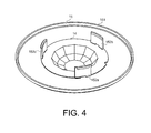
FIG. 4 shows a cap and lens of the system for mounting electronics shown in FIG. 1, according to an illustrative embodiment of the invention.
FIG. 5a is a bottom view of the system for mounting electronics in an assembled configuration, according to an illustrative embodiment of the invention.
FIG. 5b is a top view of the system for mounting electronics in an assembled configuration, according to an illustrative embodiment of the invention.
FIG. 6 shows the assembled system for mounting electronics in an open position, according to an illustrative embodiment of the invention.
FIG. 7 shows the assembled system for mounting electronics in a partially closed position, according to an illustrative embodiment of the invention.
FIG. 8 is a side view the assembled system for mounting electronics installed in a ceiling, according to an illustrative embodiment of the invention.
FIG. 9 is a side view of the assembled system for mounting electronics installed in a ceiling with variable width, according to an illustrative embodiment of the invention.
FIG. 10 is a side view of the assembled system for mounting electronics installed in a ceiling with an irregular opening, according to an embodiment of the invention.
FIG. 11 is a side view of the assembled system for mounting electronics installed in a ceiling with a nearby wall joist, according to an illustrative embodiment of the invention.
FIG. 12 is a flowchart illustrating a method for mounting electronics in a planar board, according to an embodiment of the invention.
LIST OF REFERENCE NUMBERS FOR THE MAJOR ELEMENTS IN THE DRAWING
The following is a list of the major elements in the drawings in numerical order.
    • 10 electronics housing
    • 11 collar
    • 12 a-c arm
    • 13 a-c threaded screw
    • 14 Fresnel lens
    • 15 cap
    • 16 battery
    • 17 PIR sensor
    • 50 ceiling
    • 61 first width
    • 62 second width
    • 101 housing flange
    • 102 a-c hole
    • 103 a-c tab
    • 104 cutout
    • 105 battery cover
    • 106 electrical connection
    • 107 battery compartment
    • 111 collar flange
    • 112 a-c slot
    • 113 a-c hole
    • 114 a-c indentation
    • 121 a-c first portion
    • 122 a-c second portion
    • 123 a-c third portion
    • 124 a-c threaded insert
    • 125 a-c arm angle
    • 126 a-c hinge
    • 127 a-c hinge
    • 128 a-c hinge
    • 151 rim
    • 152 a-c tab
    • 501 exterior surface
    • 502 interior surface
    • 503 peripheral surface
    • 504 beam
    • 1001 length between first arm and peripheral surface
    • 1002 length between second arm and peripheral surface
    • 1201 (step of) inserting first threaded screw through collar and arm
    • 1202 (step of) inserting second threaded screw through collar and arm
    • 1203 (step of) aligning electronic housing with collar
    • 1204 (step of) detachably connecting electronics housing to collar
    • 1205 (step of) inserting collar in opening in ceiling
    • 1206 (step of) compressing first arm to a first desired angle
    • 1207 (step of) compressing second arm to a second desired angle
    • 1208 (step of) inserting a lens filter in a cap
    • 1209 (step of) detachably connecting cap to electronics housing
DETAILED DESCRIPTION OF THE INVENTION
The present invention provides a mount assembly. More particularly, the present invention provides a mount assembly accessible from an exterior surface of a ceiling or wall and which requires no access to areas behind the external surface. At least two independently controlled arms support the assembly in the wall or ceiling. Individual components of the mount assembly snap in place for simple hardware-free assembly.
Throughout the specification, the mount assembly is described in the context of mounting a passive infrared (PIR) sensor in a ceiling. However, the present invention should not be limited to mounting PIR sensors. In another example, the mounted electronic device may be a wireless gateway for wireless communication on a network. In yet another example, the electronic device may be a speaker. It is contemplated that the mount assembly may mount non-electronic devices as well. For example, the mount assembly may be employed to mount decorative or functional structures in a wall.
Similarly, the mount assembly is not limited to use with a ceiling. The mount may be used to mount a device in any planar board. For example, the planar board may be a portion of a ceiling, floor, wall, table top, desk top or wooden beam. Additionally, the planar board is not limited to a certain material. The planar board may be comprise a panel sheetrock, or plaster.
FIG. 1 is an exploded diagram of a system for mounting electronics in a wall, according to an illustrative embodiment of the invention. The system comprises an electronics housing 10 and a mount assembly further comprising a collar 11, a first arm 12 a, a second arm 12 b, a third arm 12 c, a first threaded screw 13 a, a second threaded screw 13 b, and a third threaded screw 13 c. The mount assembly and electronics housing 10 are inserted into an opening in a ceiling and supported in space by the three arms 12 a-c engaging an inner surface of the wall, such as an interior peripheral surface of the opening or the interior surface of the ceiling.
While the mount assembly in the embodiment shown in FIG. 1 comprises three arms, the present invention should not be limited to three arms. Embodiments comprising two arms and greater than three arms fall within the scope of the invention. As will described below, the number of certain elements of the system are dependent on the number of arms of the mount assembly. Accordingly, it is contemplated that embodiments of the invention will comprise two of each of these elements or greater than three of each of these elements.
FIG. 2 shows a mount assembly of the system for mounting electronics shown in FIG. 1, according to an illustrative embodiment of the invention. The collar 11 is cylindrical with an annular cross section and is dimensioned to fit around the electronics housing 10. The collar 11 further comprises a collar flange 111 extending perpendicularly from the bottom of the collar 11. When inserted in the ceiling, the top surface of the collar flange 111 is configured to communicate with the exterior surface of the ceiling. The bottom surface of the collar flange 111 is configured to communicate with the top surface of a flange 101 of the electronics housing 10 (FIG. 3). This configuration provides a flush appearance with the ceiling.
In this embodiment the collar 11 is cylindrical with a uniform annular cross section but the shape of the collar 11 should not be limited to this embodiment. It is contemplated that the cross section may be non-uniform or that the inner or outer shape of the cross section of the collar 11 may be a shape other than a circle, such as octagonal, rectangular, star or any other similar shape. For example, in an embodiment of the invention in which the housing has a rectangular cross section, the inner peripheral surface of the collar 11 may be rectangular, while the outer peripheral surface of the collar 11 may be cylindrical. Additionally, it should be noted that the collar flange 111 need only be flush with the ceiling when the mount assembly is installed in the ceiling. Depending on the shape of the collar 11, the collar flange 111 does not need to extend perpendicularly from the bottom of the collar 11 (FIG. 3). For example, in another embodiment, the collar 11 may have a non-uniform cross section tapering at the top with a collar flange 111 extending at an obtuse angle from the collar 11.
The collar 11 comprises at a first slot 112 a, a second slot 112 b and a third slot 112 c extending from the outer peripheral surface of the collar to an inner peripheral surface of the collar. Each of the at least one slots 112 a-c communicates with a corresponding at least one tab 103 a-c of the electronics housing 10 to attach the electronics housing 10 to the collar 11. The electronics housing 10 may be detached from the collar 11 by disengaging each tab 103 a-c from each corresponding slot 112 a-c.
Additionally, the collar 11 comprises three holes 113 a-c extending axially from a top surface of the collar 11 to the bottom surface of the collar 11. As described above, the minimum number of holes in the collar is dependent on the number of arms of the mount assembly. In this embodiment, the collar 11 comprises three holes 113 a-c but should not be limited to the three holes 113 a-c in this embodiment. In other embodiments, the collar 11 comprises any number of holes 113 greater than one and corresponding to the number of arms 12 and threaded screws 13.
Three arms 12 a-c are coupled to the collar 11 each at a hinge 126 a-c and equidistant from the other arms. In this embodiment, the mount assembly comprises three arms 12 a-c but the mount assembly should not be limited to three arms. Embodiments with more than three arms 12 a-c and less than three arms 12 a-c are contemplated by the invention. In this embodiment, the three arms extend from the indentations 114 in the collar flange 111. Each arm 12 a-c is composed of a first portion 121 a-c, a second portion 122 a-c and a third portion 123 a-c, respectively. The first portion 121 a-c and the second portion 122 a-c meet at a hinge 128 a-c and the second portion 122 a-c and third portion 123 a-c meet at a hinge 127 a-c. The first portion 121 a-c of each arm 12 a-c has a threaded insert 124 a-c through the width of the first portion 121 a-c extending from the top surface of the portion to the bottom surface of the portion.
In this embodiment, the arms 12 a-c are formed from a single piece of nylon having varying thickness, thereby providing rigidity in the first, second and third portions and flexibility at the hinge. However, the arms may be composed of one or more materials. For example, each portion of the arm may be composed of a distinct rigid block, the blocks connected by hinges. Additionally, in an embodiment of the invention, the arms 12 a-c and collar 11 are integrally formed from a single piece of material. In this embodiment, the arms 12 a-c may be coupled to the collar flange 111 at an indentation in the collar 11 to ensure proper setback from the radial edge of the collar flange.
In an embodiment of the invention, the third portion 123 a-c of each arm 12 a-c further comprises one or more ribs on an outer surface to provide increased mechanical resistance between the arm 12 a-c and the surface of the ceiling.
FIG. 3 shows an electronics housing of the system for mounting electronics shown in FIG. 1, according to an illustrative embodiment of the invention. The electronics housing 10 comprises a cylindrical body and contains components of the electronic device 17. The electronics housing 10 further comprises a housing flange 101 extending from the bottom of the housing. The top surface the electronics housing flange 101 is configured for communicating with a bottom surface of the collar flange 111. The electronics housing 10 further comprises at least three tabs 103 a-c, each disposed in a cutout 104 a-c of the electronics housing 10 for detachably connecting the electronics housing 10 with the collar 11 by communicating with the three slots 112 a-c of the collar 11 (FIG. 2). A slot is formed in the gap between each cutout 104 a-c and tab 103 a-c. The electronics housing 10 further has three holes 102 a-c corresponding to the three holes 113 a-c of the collar 11 (FIG. 2). As described above in reference to the collar holes 113, in this embodiment, the housing comprises three holes 113 but should not be limited to three.
In an embodiment of the invention, the electronics housing 10 further comprises a battery compartment 107 defined by an indentation in the outer peripheral surface and configured for receiving one or more electrical power sources 16. For example, the battery case may receive a Lithium Ion (Li-ion) battery providing 4.2 V DC. The electronics housing 10 further comprises a battery cover 105 for the battery compartment 107 and an electrical connection 106 at the bottom of the indentation extending through the electronics housing 10 to electrically couple the electronic components of the electrical device with the one or more electrical power sources 16. In other embodiments of the invention, the electronics housing 10 comprises a hole defined by the outer peripheral surface configured for receiving an electrical conductor for receiving electrical power.
In embodiments of the invention, the electronic device may communicate wired or wirelessly with external devices. For example, in an embodiment of the invention, the electronic device may comprise an RF transceiver for bi-directional communication with an external device. In another embodiment of the invention, the electronic device may be configured for wired communication with an external device, such as via one or more electrical conductors configured for communication received through the opening in the housing.
Each of the three threaded screws 13 a-c extends through a corresponding hole 113 a-c in the collar 11 and a corresponding threaded insert 124 a-c in the first portion 121 a-c of the arm 12 a-c. The head of each threaded screw 13 a-c communicates with the bottom surface of the collar flange 111 and protrudes through a corresponding hole 102 a-c of the electronics housing flange 101 providing access to the threaded screw 13 a-c for installers. The thread on the screw 13 a-c and the thread in the threaded insert 124 a-c are configured such that the threaded screw 13 a-c may be screwed into the threaded insert 124 a-c.
In this embodiment the screws are threaded screws. However, the screws should not be limited to threaded screws. The mount assembly may comprises any screw that is configured for securing the insert to the screw. For example, in an embodiment of the invention, the mount assembly may comprise a ratcheting screw comprising ridges configured for communicating with ridges in a corresponding insert. The ridges on the screw and in the insert are dimensioned to allow the screw to be inserted in one direction through the insert but impede the screw from being pulled through the insert in the opposite direction.
In this illustrative embodiment, the electronics housing 10 houses a passive infrared (PIR) sensor 17. The system further comprises a Fresnel lens 14 and a cap 15. The Fresnel lens 14 is configured to be held in space by the cap 15 and may be protruding through the bottom surface of the cap 15. In an embodiment of the invention, the PIR lens is contained in the electronics housing. In this embodiment, the system further comprises a lens filter. The lens filter may be a flat disc supported in space by the cap 15.
FIG. 4 shows a cap 15 and lens 14 of the system for mounting electronics shown in FIG. 1, according to an illustrative embodiment of the invention. The cap 15 is disc with an extended rim 151. Depending on application, the cap 15 may hold components, such as a lens filter 14, in place or it may serve as a decorative piece. In embodiments of the invention, such as in embodiments when the lens filter 14 is a Fresnel lens, the cap 15 may be an annular disc. The cap 15 further comprises three tabs 152 a-c disposed on a top surface of the cap 15 configured for communicating with the three slots formed between each tab 103 a-c and each cutout 104 a-c of the electronics housing 10. While this embodiment comprises three tabs 152 a-c, the cap 15 may comprise at least one tab and should not be limited to three tabs. The cap 15 is dimensioned to communicate with the bottom surface of the electronics housing 10 and cover the electronics housing flange 101 and collar flange 111 thereby providing a more aesthetically pleasing and flush appearance with the ceiling.
FIG. 5a is a bottom view of the system for mounting electronics in an assembled configuration, according to an illustrative embodiment of the invention. FIG. 5b is a top view of the system for mounting electronics in an assembled configuration, according to an illustrative embodiment of the invention. When the system is in an assembled configuration, the housing 10 is inserted into and attached to the collar 11. The at least one tab 103 a-c on the housing 10 snaps into the at least one slot 112 a-c of the collar 11 to detachably attach the electronics housing 10 to the collar 11. The upper surface of the housing flange 101 communicates with the bottom surface of the collar flange 111. Each hole 102 a-c in the housing flange 101 is aligned along the same vertical axis as a corresponding hole 113 a-c in the collar 11 and a corresponding threaded insert 124 a-c in an arm 12 a-c.
In an embodiment of the invention with the cap 15, the tabs 152 a-c on the cap 15 snaps into the corresponding slots 112 a-c in the collar 11. A top surface of the cap 15 communicates with the bottom surface of the housing flange 101. The extended rim 151 communicates with the exterior surface of the wall. The cap 15 offers an aesthetically pleasing surface and may be easily removed for painting or other adjustments.
FIG. 6 shows the assembled system for mounting electronics in an open position, according to an illustrative embodiment of the invention. FIG. 7 shows the assembled system for mounting electronics in a partially closed position, according to an illustrative embodiment of the invention. When in an open position, the arm angle 125 a-c between the second portion 122 a-c and third portion 123 a-c of each arm 12 a-c is less acute than in a closed position and provides a minimal horizontal profile for inserting into an opening in the ceiling. For each arm 12 a-c, as its corresponding screw 13 a-c is turned in a first direction the first portion 121 a-c of the arm 12 a-c is lowered along the length of the screw 13 a-c thereby transitioning the arm angle 125 a-c between the first portion 121 a-c and the second portion 122 a-c from obtuse to acute. As the arm 12 a-c progresses lower along the length of the screw 13 a-c, the arm angle 125 a-c becomes more acute and the magnitude of the angle degree decreases. Advantageously, each arm 12 a-c is configured to be independently compressed with respect to the other arms. Depending on the opening dimensions and ceiling thickness, each arm 12 a-c may be closed to any desired angle degree from fully open to fully closed. As described below, this allows for each arm 12 a-c to be set at different arm angle 125 a-c to account for varying thickness of the ceiling, interior impedances like joists and studs and oversized openings in the ceiling.
FIG. 8 is a side view of the assembled system for mounting electronics installed in a ceiling, according to an illustrative embodiment of the invention. The collar 11 with the attached housing 10 is inserted into the opening in the ceiling 50. The top surface of the collar flange 111 is flush with the exterior surface 501 of the ceiling. Each of the arms 12 a-c is compressed to a suitable arm angle 125 a-c to engage an inner surface of the ceiling (i.e. the inner peripheral surface 503 of the opening or interior 502 surface of the ceiling 50) and provide sufficient mechanical resistance to support the collar 11 and electronics housing 10. Advantageously, each arm 12 a-c is engaged independently and may be compressed to individual angles 125 a-c to allow for unique conditions in the ceiling 50 as will be described below.
FIG. 9 is a side view of the assembled system for mounting electronics installed in a ceiling with variable width, according to an illustrative embodiment of the invention. The width 62 of the portion of the ceiling 50 contiguous to the first arm 12 a is wider than the width 61 of the portion of the ceiling 50 contiguous to the second arm 12 b. Accordingly, the second arm 12 b is compressed further than the first arm 12 a as evidenced by the first portion 121 b of the second arm 12 b being closer to the ceiling 50 than the first portion 121 a of the first arm 12 a, as well as the arm angle 125 b of the second arm 12 b being more acute than the arm angle 125 a of the first arm 12 a.
FIG. 10 is a side view of the assembled system for mounting electronics installed in a ceiling with an irregular opening, according to an embodiment of the invention. In this exemplary installation, the ceiling 50 has an irregular opening for the mounting assembly. Accordingly, the length 1002 between the first arm 12 a and the peripheral surface 503 of the ceiling 50 is greater than the length 1001 between the second arm 12 b and the peripheral surface 503 of the ceiling 50. The first arm 12 a is compressed further than the second arm 12 b as evidenced by the first portion 121 a of the first arm 12 a being closer to the ceiling 50 than the first portion 121 b of the second arm 12 b as well as the arm angle 125 a of the first arm 12 a being more acute than the arm angle 125 b of the second arm 12 b.
FIG. 11 is a side view of the assembled system for mounting electronics installed in a ceiling with a nearby wall joist, according to an illustrative embodiment of the invention. In this exemplary installation, the opening in the ceiling is near an impediment, such as a beam, joist or stud. The impediment 504 does not allow the first arm 12 a to compress enough to engage the peripheral surface 503 of the ceiling 50. Accordingly, the first arm 12 a is compressed until it engages the impediment 504, thereby providing suitable supporting friction. The first arm 12 a does not need to be compressed as much as the second arm 12 b to engage the impediment 504. Accordingly, the arm angle 125 a of the first arm 12 a is greater than the arm angle 125 b of the second arm 12 b.
FIG. 12 is a flowchart illustrating a method for mounting electronics in a wall, according to an embodiment of the invention. In step 1201, a first threaded screw 13 a is inserted through a first hole 113 a in a collar 11 and a threaded insert 124 a in a first arm 12 a coupled to the collar 11.
In step 1202, at least a second threaded screw 13 b is inserted through a second hole 113 b in the collar 11 and threaded insert 124 b in a second arm 12 b coupled to the collar 11. In this embodiment, the method comprises the steps of engaging two arms to the mounting surface. However, the invention should not be limited to two arms. In a further embodiment of the invention, the method comprises the step 1203 of aligning the electronic housing 10 with collar 11.
In step 1204, the electronics housing 10 is detachably connected to the collar 11 by inserting the electronics housing 10 in the collar 11.
In step 1205, the collar 11 is inserted in an opening of the wall.
In step 1206, the first arm 12 a is compressed to a first desired arm angle 125 a by rotating the first threaded screw 13 a thereby engaging the opening of the wall.
In step 1207, at least a second arm 12 b is compressed to a second desired arm angle 125 b by rotating the second threaded screw 12 b thereby engaging the opening of the wall. As noted above, in this embodiment, the method comprises steps for compressing at least two arms. The method should not be limited to two arms. In a further embodiment of the invention, the method comprises a step for compressing a third arm 12 c to a third desired arm angle 125 c by rotating a third threaded screw 13 c thereby engaging the opening of the wall.
In a further embodiment of the invention, the method further comprises the steps of inserting a Fresnel lens 14 in a cap 15 (step 1208) and detachably connecting the cap 15 to the electronics housing 10 by inserting the cap 15 into the electronics housing 10 (step 1209).
In another embodiment of the invention, the method further comprises the step of aligning the electronic housing 10 with the collar 11 by aligning one or more holes 102 a-c in a flange 101 of the electronics housing 10 with one or more holes 113 a-c in the collar 11 (step 1203).
INDUSTRIAL APPLICABILITY
To solve the aforementioned problems, the present invention is a unique device in which a mounting assembly utilizes at least two independently controlled arms to support an electronic device in a ceiling.
List of Acronyms Used in the Detailed Description of the Invention
The following is a list of the acronyms used in the specification in alphabetical order.
DC direct current
Li-ion lithium ion
PIR passive infrared
V Volts
Alternate Embodiments
Alternate embodiments may be devised without departing from the spirit or the scope of the invention. For example, the body of the mount housing and collar opening may be a shape other than cylindrical, such as octagonal or rectangular.

Claims (20)

What is claimed is:
1. A system for mounting electronics in a wall, the system comprising:
an electronics housing;
a collar dimensioned to fit around and detachably connect to the electronics housing; and
at least two arms coupled to the collar at a hinge to support the collar in the wall by being compressibly engaged with an inner surface of the wall, each of the at least two arms comprising:
a first portion comprising a threaded insert extending from a top surface of the first portion to a bottom surface of the first portion, the threaded insert receiving a threaded screw,
a second portion meeting the first portion at a hinge, and
a third portion meeting the second portion at a hinge, wherein the second and third portions meet at an angle,
wherein rotation of the threaded screw in a first direction translates the first portion along a length of the threaded screw and compresses the arm by decreasing the angle between the second and third portions, thereby compressibly engaging the arm with the inner surface of the wall.
2. The system of claim 1 wherein the collar further comprises a slot extending from an outer peripheral wall to an inner peripheral wall of the collar and the electronics housing further comprises a tab configured for communicating with the slot of the collar for detachably connecting the electronics housing to the collar.
3. The system of claim 1 wherein the electronics housing further comprises a housing flange extending from a bottom of the electronics housing, and the collar further comprises a collar flange extending from a bottom of the collar, wherein a top surface of the collar flange configured for communicating with an exterior surface of the wall and a bottom surface of the flange communicates with a top surface of the collar flange.
4. The system of claim 1 further comprising a cap configured for detachably connecting to the housing and further configured for covering the opening in the wall.
5. The system of claim 4 wherein the cap comprises a disc with a raised edge and at least one tab.
6. The system of claim 1 wherein the electronics is a passive infrared (PIR) sensor.
7. The system of claim 6 wherein the PIR sensor is configured for wireless communication.
8. The system of claim 6 wherein the PIR sensor is battery powered.
9. The system of claim 6 wherein the PIR sensor further comprises a wired interface and wherein the top surface of the housing comprises an opening configured for receiving a wire.
10. The system of claim 6 further comprising a PIR lens filter.
11. The system of claim 10 wherein the PIR lens filter is a flat disc.
12. The system of claim 6 further comprising a Fresnel lens wherein a portion of the lens extends beyond a bottom surface of the cap.
13. The system of claim 1, wherein rotation of the threaded screw in a second direction translates the first portion along the length of the threaded screw and decompresses the arm by increasing the angle between the second and third portions.
14. The system of claim 1, wherein the wall comprises at least one selected from the group consisting of a planar board, a portion of a ceiling, a portion of a floor, a portion of a side wall, a table top, a desk top, a wooden beam, a panel sheetrock, and a plaster.
15. The system of claim 1, wherein the collar comprises at least two holes, each receiving a first end of the threaded screw, and wherein the threaded insert of the first portion receives a second end of the threaded screw.
16. The system of claim 1, wherein the wall contiguous to the collar has a varying width, varying distance to the collar, or comprises a joint, a beam, a joist, or a stud.
17. The system of claim 5, wherein the electronics housing comprises at least one slot and wherein the at least one tab of the cap communicates with the at least one slot of the electronics housing.
18. The system of claim 1, wherein each arm of the at least two arms compresses and decompresses to individual angles independently of the other arm.
19. A system for mounting electronics in a wall, the system comprising:
an electronics housing;
a collar dimensioned to fit around and detachably connect to the electronics housing; and
at least two arms coupled to the collar to support the collar in the wall by being compressibly engaged with an inner surface of the wall, each of the at least two arms comprising:
a first portion comprising a threaded insert extending from a top surface of the first portion to a bottom surface of the first portion, the threaded insert receiving a threaded screw,
a second portion comprising (a) a first end connected to the first portion at a first hinge, and (b) a second end, and
a third portion comprising (a) a first end connected to the second end of the second portion at a second hinge, and (b) a second end connected to the collar at a third hinge, wherein the second and third portions meet at an angle,
wherein rotation of the threaded screw in a first direction translates the first portion along a length of the threaded screw and compresses the arm by decreasing the angle between the second and third portions, thereby compressibly engaging the arm with the inner surface of the wall.
20. A system for mounting electronics in a wall, the system comprising:
an electronics housing;
at least two arms connected to the electronic housing to support the electronics housing in the wall by being compressibly engaged with an inner surface of the wall, each of the at least two arms comprising:
a first portion comprising a threaded insert extending from a top surface of the first portion to a bottom surface of the first portion, the threaded insert receiving a threaded screw,
a second portion comprising (a) a first end connected to the first portion at a first hinge, and (b) a second end, and
a third portion comprising (a) a first end connected to the second end of the second portion by a second hinge, and (b) a second end that meets the electronics housing at a third hinge, wherein the second and third portions meet at an angle,
wherein rotation of the threaded screw in a first direction translates the first portion along a length of the threaded screw and compresses the arm by decreasing the angle between the second and third portions, thereby compressibly engaging the arm with the inner surface of the wall.
US13/486,667 2012-06-01 2012-06-01 Mount assembly Active 2033-12-18 US9407074B2 (en)

Priority Applications (1)

Application Number Priority Date Filing Date Title
US13/486,667 US9407074B2 (en) 2012-06-01 2012-06-01 Mount assembly

Applications Claiming Priority (1)

Application Number Priority Date Filing Date Title
US13/486,667 US9407074B2 (en) 2012-06-01 2012-06-01 Mount assembly

Publications (2)

Publication Number Publication Date
US20130319752A1 US20130319752A1 (en) 2013-12-05
US9407074B2 true US9407074B2 (en) 2016-08-02

Family

ID=49668872

Family Applications (1)

Application Number Title Priority Date Filing Date
US13/486,667 Active 2033-12-18 US9407074B2 (en) 2012-06-01 2012-06-01 Mount assembly

Country Status (1)

Country Link
US (1) US9407074B2 (en)

Cited By (2)

* Cited by examiner, † Cited by third party
Publication number Priority date Publication date Assignee Title
US10544933B2 (en) 2018-04-04 2020-01-28 Abl Ip Holding Llc Light fixture with rotatable speakers
USD883548S1 (en) 2018-04-27 2020-05-05 Abl Ip Holding Llc Light fixture with rotatable end

Families Citing this family (10)

* Cited by examiner, † Cited by third party
Publication number Priority date Publication date Assignee Title
GB2484269A (en) * 2010-10-01 2012-04-11 Thorn Security Mounting unit
NZ705404A (en) * 2012-09-07 2017-11-24 Csr Building Products Ltd System for optimising an enclosed space
EP3035305B1 (en) 2014-12-18 2016-11-16 Axis AB Enclosure and arrangement for recess mounting of a camera or camera head
US10798797B1 (en) * 2016-03-28 2020-10-06 Douglas Lighting Controls Ceiling mount sensor assembly
WO2017223572A1 (en) * 2016-06-24 2017-12-28 Anderson William Carl Iii Mounted enclosure for communication components
US10418791B2 (en) 2016-09-14 2019-09-17 Bjorn Jensen Mount for access point
US10545039B2 (en) * 2017-01-25 2020-01-28 Enlighted, Inc. Environment sensor mounting assembly
WO2019140379A2 (en) * 2018-01-12 2019-07-18 3M1S, Llc In-wall amplifier and controller housing and related methods
US10524328B1 (en) 2018-03-30 2019-12-31 Douglas Lighting Controls Fixture mount sensor with remote energy usage reporting
CN112039009B (en) * 2020-08-25 2021-11-09 广西电网有限责任公司钦州供电局 Box-shaped lightning arrester with rotary positioning support

Citations (8)

* Cited by examiner, † Cited by third party
Publication number Priority date Publication date Assignee Title
US4887073A (en) * 1988-04-08 1989-12-12 Matsushita Electric Works, Ltd. Ceiling mounted fire detector assembly
US6377182B1 (en) 1999-11-16 2002-04-23 Brk Brands, Inc. Smoke detector with sensor having improved mounting configuration
US20030223240A1 (en) * 2002-05-31 2003-12-04 #9060-0495 Quebec, Inc. Recessed light fixture
US20060237651A1 (en) * 2005-04-22 2006-10-26 Honeywell International Inc Recessed ceiling mounted passive infrared detector
US20060256452A1 (en) * 2005-05-11 2006-11-16 Everspring Industry Co., Ltd. Thin-type spherical lens
US7628366B2 (en) 2006-09-05 2009-12-08 Vtc Electronics Corporation Ceiling mount
US20120327242A1 (en) * 2011-06-27 2012-12-27 Barley Christopher B Surveillance camera with rapid shutter activation
US8544807B2 (en) * 2008-07-30 2013-10-01 Pelco, Inc. Apparatus for mounting a surveillance camera

Patent Citations (9)

* Cited by examiner, † Cited by third party
Publication number Priority date Publication date Assignee Title
US4887073A (en) * 1988-04-08 1989-12-12 Matsushita Electric Works, Ltd. Ceiling mounted fire detector assembly
US6377182B1 (en) 1999-11-16 2002-04-23 Brk Brands, Inc. Smoke detector with sensor having improved mounting configuration
US20030223240A1 (en) * 2002-05-31 2003-12-04 #9060-0495 Quebec, Inc. Recessed light fixture
US20060237651A1 (en) * 2005-04-22 2006-10-26 Honeywell International Inc Recessed ceiling mounted passive infrared detector
US7335886B2 (en) 2005-04-22 2008-02-26 Honeywell International Inc. Recessed ceiling mounted passive infrared detector
US20060256452A1 (en) * 2005-05-11 2006-11-16 Everspring Industry Co., Ltd. Thin-type spherical lens
US7628366B2 (en) 2006-09-05 2009-12-08 Vtc Electronics Corporation Ceiling mount
US8544807B2 (en) * 2008-07-30 2013-10-01 Pelco, Inc. Apparatus for mounting a surveillance camera
US20120327242A1 (en) * 2011-06-27 2012-12-27 Barley Christopher B Surveillance camera with rapid shutter activation

Cited By (2)

* Cited by examiner, † Cited by third party
Publication number Priority date Publication date Assignee Title
US10544933B2 (en) 2018-04-04 2020-01-28 Abl Ip Holding Llc Light fixture with rotatable speakers
USD883548S1 (en) 2018-04-27 2020-05-05 Abl Ip Holding Llc Light fixture with rotatable end

Also Published As

Publication number Publication date
US20130319752A1 (en) 2013-12-05

Similar Documents

Publication Publication Date Title
US9407074B2 (en) Mount assembly
US9622321B2 (en) Systems, devices and methods for controlling one or more lights
US11025023B2 (en) Smart quick connect device for electrical fixtures
US20220003399A1 (en) Modular smart quick connect device for electrical fixtures
US7109418B2 (en) Adapter for mounting a faceplate of a first style on to an electrical outlet cavity of a second style
US20100296685A1 (en) Adapter and electronic devices for recessed light socket
US9608420B1 (en) Flush mounting utility component assembly
US20210273434A1 (en) Weatherproof electrical enclosure with reinforcement
US9101051B1 (en) Flush mounting utility component assembly
US6483031B2 (en) Mounting bracket and extra-low voltage control device for installation with an electrical outlet box
US20150349504A1 (en) Faceplate and hanging device
US20090107083A1 (en) Multicategory Collection of Ceiling/Wall Devices With Familial Appearances
US7060899B1 (en) Pre-wiring assembly system and method
US10890315B2 (en) Universal mounting assembly
US20090095861A1 (en) Wall mounting bracket with slidable wing
US20060284024A1 (en) Audio component mounting assembly
US11437755B2 (en) Controller and system
US20050109907A1 (en) Truncated round electrical fixture box
US20230088623A1 (en) Light fixture installation adapters and methods thereof
NO345404B1 (en) Mounting bracket and method for mounting an object to a connection box

Legal Events

Date Code Title Description
AS Assignment

Owner name: CRESTRON ELECTRONICS INC., NEW JERSEY

Free format text: ASSIGNMENT OF ASSIGNORS INTEREST;ASSIGNORS:COWLES, WILLIAM;FELDSTEIN, WENDY;FELDSTEIN, GEORGE;AND OTHERS;SIGNING DATES FROM 20120607 TO 20120608;REEL/FRAME:028376/0171

STCF Information on status: patent grant

Free format text: PATENTED CASE

CC Certificate of correction
MAFP Maintenance fee payment

Free format text: PAYMENT OF MAINTENANCE FEE, 4TH YEAR, LARGE ENTITY (ORIGINAL EVENT CODE: M1551); ENTITY STATUS OF PATENT OWNER: LARGE ENTITY

Year of fee payment: 4

MAFP Maintenance fee payment

Free format text: PAYMENT OF MAINTENANCE FEE, 8TH YEAR, LARGE ENTITY (ORIGINAL EVENT CODE: M1552); ENTITY STATUS OF PATENT OWNER: LARGE ENTITY

Year of fee payment: 8