US9406914B2 - Annular device with battery cover - Google Patents
Annular device with battery cover Download PDFInfo
- Publication number
- US9406914B2 US9406914B2 US14/079,524 US201314079524A US9406914B2 US 9406914 B2 US9406914 B2 US 9406914B2 US 201314079524 A US201314079524 A US 201314079524A US 9406914 B2 US9406914 B2 US 9406914B2
- Authority
- US
- United States
- Prior art keywords
- arcuate
- hole
- arcuate member
- annular device
- protrusion
- Prior art date
- Legal status (The legal status is an assumption and is not a legal conclusion. Google has not performed a legal analysis and makes no representation as to the accuracy of the status listed.)
- Expired - Fee Related, expires
Links
Images


Classifications
-
- H—ELECTRICITY
- H01—ELECTRIC ELEMENTS
- H01M—PROCESSES OR MEANS, e.g. BATTERIES, FOR THE DIRECT CONVERSION OF CHEMICAL ENERGY INTO ELECTRICAL ENERGY
- H01M50/00—Constructional details or processes of manufacture of the non-active parts of electrochemical cells other than fuel cells, e.g. hybrid cells
- H01M50/20—Mountings; Secondary casings or frames; Racks, modules or packs; Suspension devices; Shock absorbers; Transport or carrying devices; Holders
- H01M50/204—Racks, modules or packs for multiple batteries or multiple cells
- H01M50/207—Racks, modules or packs for multiple batteries or multiple cells characterised by their shape
- H01M50/213—Racks, modules or packs for multiple batteries or multiple cells characterised by their shape adapted for cells having curved cross-section, e.g. round or elliptic
-
- H01M2/1055—
-
- E—FIXED CONSTRUCTIONS
- E05—LOCKS; KEYS; WINDOW OR DOOR FITTINGS; SAFES
- E05C—BOLTS OR FASTENING DEVICES FOR WINGS, SPECIALLY FOR DOORS OR WINDOWS
- E05C19/00—Other devices specially designed for securing wings, e.g. with suction cups
- E05C19/06—Other devices specially designed for securing wings, e.g. with suction cups in which the securing part if formed or carried by a spring and moves only by distortion of the spring, e.g. snaps
-
- H01M2/1022—
-
- H—ELECTRICITY
- H01—ELECTRIC ELEMENTS
- H01M—PROCESSES OR MEANS, e.g. BATTERIES, FOR THE DIRECT CONVERSION OF CHEMICAL ENERGY INTO ELECTRICAL ENERGY
- H01M50/00—Constructional details or processes of manufacture of the non-active parts of electrochemical cells other than fuel cells, e.g. hybrid cells
- H01M50/20—Mountings; Secondary casings or frames; Racks, modules or packs; Suspension devices; Shock absorbers; Transport or carrying devices; Holders
- H01M50/271—Lids or covers for the racks or secondary casings
-
- Y—GENERAL TAGGING OF NEW TECHNOLOGICAL DEVELOPMENTS; GENERAL TAGGING OF CROSS-SECTIONAL TECHNOLOGIES SPANNING OVER SEVERAL SECTIONS OF THE IPC; TECHNICAL SUBJECTS COVERED BY FORMER USPC CROSS-REFERENCE ART COLLECTIONS [XRACs] AND DIGESTS
- Y02—TECHNOLOGIES OR APPLICATIONS FOR MITIGATION OR ADAPTATION AGAINST CLIMATE CHANGE
- Y02E—REDUCTION OF GREENHOUSE GAS [GHG] EMISSIONS, RELATED TO ENERGY GENERATION, TRANSMISSION OR DISTRIBUTION
- Y02E60/00—Enabling technologies; Technologies with a potential or indirect contribution to GHG emissions mitigation
- Y02E60/10—Energy storage using batteries
Definitions
- the present disclosure relates to devices and, particularly, to an annular device with a battery cover.
- An electronic device such as a television remote usually has a rectangular profile and includes a removable battery cover.
- the battery cover can be removably connected to the main body of the remote by conventional connection techniques.
- the conventional connection techniques may not be suitable for devices with unusual shapes such as annular.
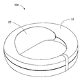
- FIG. 1 is an isometric, assembled view of an annular device in accordance with an exemplary embodiment.
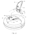
- FIG. 2 is an exploded, isometric view of the annular device in FIG. 1 .
- FIG. 3 is an exploded, isometric view of the annular device of FIG. 1 viewed from another viewpoint.
- FIG. 1 is an isometric, assembled view of an annular device 100 .
- the annular device 100 includes a main body 10 and a battery cover 20 connected to the main body 10 .
- the main body 10 is substantially ring-shaped.
- a battery mounting portion 30 protrudes from an inner face of the main body 10 .
- the battery mounting portion 30 includes a first arcuate element 31 and a second arcuate element 32 opposite to each other.
- the first arcuate element 31 and the second arcuate element 32 cooperatively define a receiving space 33 for receiving one or more batteries (not shown).
- the second arcuate element 32 defines an opening 34 for accessing the receiving space 33 .
- the cover 20 covers the opening 34 for securing the batteries in the receiving space 33 . When the cover 20 is removed from the opening 34 , the batteries can be taken out through the opening 34 .
- the shape of the battery cover 20 matches the shape of the battery mounting portion 30 .
- the battery cover 20 includes a first arcuate member 21 and a second arcuate member 22 opposite to each other.
- the annular device 100 also includes a first fastening portion for connecting the first arcuate member 21 with the first arcuate element 31 , and a second fastening portion for connecting the second arcuate member 22 with the second arcuate element 32 .
- the first fastening portion includes two first protrusions 211 and two corresponding cutouts 311 .
- the two first protrusions 211 are formed on the inner surface of the first arcuate member 21 .
- the two cutouts 311 are defined in the outer surface of the first arcuate element 31 .
- the first protrusions 211 can be respectively fit into the cutouts 311 .
- the second fastening portion includes a protruding tab 221 and a restriction groove 322 .
- the protruding tab 221 protrudes from an edge of the second arcuate member 22 at a middle position.
- a clasping hole 222 is defined in the protruding tab 221 .
- the restriction groove 322 is formed in the inner surface of the main body 10 , and communicates with the opening 34 .
- the restriction groove 322 is used to receive the protruding tab 221 .
- the bottom of the groove 322 includes a second protrusion 321 .
- the cover 20 When attaching the battery cover 20 onto the battery mounting portion 30 , the cover 20 is orientated to cause the protruding tab 221 to align with the groove 322 . The cover 20 is then pushed to allow the protruding tab 221 to move into the groove 322 . During the pushing, the first arcuate member 21 and the second arcuate member 22 are caused to move a little away from each other, until the second protrusion 321 is received in the clasping hole 222 and the first protrusions 211 are received in the cutouts 311 , which tightly connects the cover 20 to the main body 10 .
Abstract
Description
Claims (5)
Priority Applications (1)
| Application Number | Priority Date | Filing Date | Title |
|---|---|---|---|
| US14/079,524 US9406914B2 (en) | 2010-02-26 | 2013-11-13 | Annular device with battery cover |
Applications Claiming Priority (4)
| Application Number | Priority Date | Filing Date | Title |
|---|---|---|---|
| CN201010114871A CN101834283A (en) | 2010-02-26 | 2010-02-26 | Annular electronic equipment |
| CN2010101148718 | 2010-02-26 | ||
| US12/889,420 US8623534B2 (en) | 2010-02-26 | 2010-09-24 | Annular device with battery cover |
| US14/079,524 US9406914B2 (en) | 2010-02-26 | 2013-11-13 | Annular device with battery cover |
Related Parent Applications (1)
| Application Number | Title | Priority Date | Filing Date |
|---|---|---|---|
| US12/889,420 Division US8623534B2 (en) | 2010-02-26 | 2010-09-24 | Annular device with battery cover |
Publications (2)
| Publication Number | Publication Date |
|---|---|
| US20140079975A1 US20140079975A1 (en) | 2014-03-20 |
| US9406914B2 true US9406914B2 (en) | 2016-08-02 |
Family
ID=42718272
Family Applications (2)
| Application Number | Title | Priority Date | Filing Date |
|---|---|---|---|
| US12/889,420 Expired - Fee Related US8623534B2 (en) | 2010-02-26 | 2010-09-24 | Annular device with battery cover |
| US14/079,524 Expired - Fee Related US9406914B2 (en) | 2010-02-26 | 2013-11-13 | Annular device with battery cover |
Family Applications Before (1)
| Application Number | Title | Priority Date | Filing Date |
|---|---|---|---|
| US12/889,420 Expired - Fee Related US8623534B2 (en) | 2010-02-26 | 2010-09-24 | Annular device with battery cover |
Country Status (2)
| Country | Link |
|---|---|
| US (2) | US8623534B2 (en) |
| CN (1) | CN101834283A (en) |
Citations (4)
| Publication number | Priority date | Publication date | Assignee | Title |
|---|---|---|---|---|
| CN1083230A (en) | 1992-08-18 | 1994-03-02 | 卡西欧计算机公司 | The electronic installation that has liquid crystal display |
| US20060287013A1 (en) | 2005-06-16 | 2006-12-21 | Lg Electronics Inc. | Battery fastening apparatus and portable terminal using the same |
| CN101588684A (en) | 2008-05-20 | 2009-11-25 | 深圳富泰宏精密工业有限公司 | Portable electron device |
| US20100119925A1 (en) * | 2008-11-13 | 2010-05-13 | Shenzhen Futaihong Precision Industry Co., Ltd. | Battery cover assembly for portable electronic device |
Family Cites Families (2)
| Publication number | Priority date | Publication date | Assignee | Title |
|---|---|---|---|---|
| CN2777910Y (en) * | 2005-01-28 | 2006-05-03 | 深圳富泰宏精密工业有限公司 | Fastening structure for cell cover |
| CN1905573B (en) * | 2005-07-29 | 2011-06-08 | 深圳富泰宏精密工业有限公司 | Fastening structure for cell cover |
-
2010
- 2010-02-26 CN CN201010114871A patent/CN101834283A/en active Pending
- 2010-09-24 US US12/889,420 patent/US8623534B2/en not_active Expired - Fee Related
-
2013
- 2013-11-13 US US14/079,524 patent/US9406914B2/en not_active Expired - Fee Related
Patent Citations (4)
| Publication number | Priority date | Publication date | Assignee | Title |
|---|---|---|---|---|
| CN1083230A (en) | 1992-08-18 | 1994-03-02 | 卡西欧计算机公司 | The electronic installation that has liquid crystal display |
| US20060287013A1 (en) | 2005-06-16 | 2006-12-21 | Lg Electronics Inc. | Battery fastening apparatus and portable terminal using the same |
| CN101588684A (en) | 2008-05-20 | 2009-11-25 | 深圳富泰宏精密工业有限公司 | Portable electron device |
| US20100119925A1 (en) * | 2008-11-13 | 2010-05-13 | Shenzhen Futaihong Precision Industry Co., Ltd. | Battery cover assembly for portable electronic device |
Also Published As
| Publication number | Publication date |
|---|---|
| CN101834283A (en) | 2010-09-15 |
| US8623534B2 (en) | 2014-01-07 |
| US20140079975A1 (en) | 2014-03-20 |
| US20110212353A1 (en) | 2011-09-01 |
Similar Documents
| Publication | Publication Date | Title |
|---|---|---|
| US8249679B2 (en) | Cover latching structure for portable electronic device | |
| US7172460B2 (en) | Universal serial bus connector with integral shell | |
| US20130037396A1 (en) | Switch assembly | |
| US20100035666A1 (en) | Portable electronic device | |
| US20130319836A1 (en) | Housing assembly having a push button | |
| US8531845B2 (en) | Structure of anti tamper case for solid state disk | |
| US9400520B2 (en) | Tablet terminal attachment | |
| US20100075212A1 (en) | Battery cover latch mechanism and portable electronic device using same | |
| US7950935B2 (en) | Electronic device with covering lid for covering insert hole | |
| US20110222212A1 (en) | Electronic device with latching mechanism | |
| US8164885B2 (en) | Electronic device with detachable cover | |
| US20070274054A1 (en) | Foolproof interlock apparatus | |
| EP3442205B1 (en) | Wearable device | |
| US9986803B2 (en) | Apparatus for holding an electronic device having a mechanical self-adjusting retention element | |
| US9406914B2 (en) | Annular device with battery cover | |
| US20100238623A1 (en) | Case structure for portable hard disk drive | |
| US6655237B2 (en) | Ratchet wrench having cover positioning device | |
| US20110052956A1 (en) | Battery cover assembly and portable electronic device utilizing the same | |
| US20120162873A1 (en) | Push button assembly and electronic device having same | |
| US20120014043A1 (en) | Portable electronic device with pendant attachment system | |
| US20150150362A1 (en) | Protection case for electronic device | |
| US20130286560A1 (en) | Battery cover assembly for portable electronic device | |
| US9800701B1 (en) | Mobile device case with integrated adaptor | |
| US11165184B2 (en) | Orientation device | |
| KR101369297B1 (en) | Protection case for mobile terminal |
Legal Events
| Date | Code | Title | Description |
|---|---|---|---|
| AS | Assignment |
Owner name: HON HAI PRECISION INDUSTRY CO., LTD., TAIWAN Free format text: ASSIGNMENT OF ASSIGNORS INTEREST;ASSIGNORS:LIU, RUI;CHENG, GANG;HE, MENG-HUA;AND OTHERS;REEL/FRAME:033470/0497 Effective date: 20100830 Owner name: HONG FU JIN PRECISION INDUSTRY (SHENZHEN) CO., LTD Free format text: ASSIGNMENT OF ASSIGNORS INTEREST;ASSIGNORS:LIU, RUI;CHENG, GANG;HE, MENG-HUA;AND OTHERS;REEL/FRAME:033470/0497 Effective date: 20100830 |
|
| AS | Assignment |
Owner name: SCIENBIZIP CONSULTING(SHENZHEN)CO.,LTD., CHINA Free format text: ASSIGNMENT OF ASSIGNORS INTEREST;ASSIGNORS:HONG FU JIN PRECISION INDUSTRY (SHENZHEN) CO., LTD.;HON HAI PRECISION INDUSTRY CO., LTD.;REEL/FRAME:037925/0925 Effective date: 20160223 |
|
| STCF | Information on status: patent grant |
Free format text: PATENTED CASE |
|
| FEPP | Fee payment procedure |
Free format text: MAINTENANCE FEE REMINDER MAILED (ORIGINAL EVENT CODE: REM.); ENTITY STATUS OF PATENT OWNER: SMALL ENTITY |
|
| LAPS | Lapse for failure to pay maintenance fees |
Free format text: PATENT EXPIRED FOR FAILURE TO PAY MAINTENANCE FEES (ORIGINAL EVENT CODE: EXP.); ENTITY STATUS OF PATENT OWNER: SMALL ENTITY |
|
| STCH | Information on status: patent discontinuation |
Free format text: PATENT EXPIRED DUE TO NONPAYMENT OF MAINTENANCE FEES UNDER 37 CFR 1.362 |