US940160A - Guarded-end steel-lever harrow. - Google Patents
Guarded-end steel-lever harrow. Download PDFInfo
- Publication number
- US940160A US940160A US45239108A US1908452391A US940160A US 940160 A US940160 A US 940160A US 45239108 A US45239108 A US 45239108A US 1908452391 A US1908452391 A US 1908452391A US 940160 A US940160 A US 940160A
- Authority
- US
- United States
- Prior art keywords
- bars
- tooth
- bar
- harrow
- guarded
- Prior art date
- Legal status (The legal status is an assumption and is not a legal conclusion. Google has not performed a legal analysis and makes no representation as to the accuracy of the status listed.)
- Expired - Lifetime
Links
- 238000004519 manufacturing process Methods 0.000 description 4
- 238000005266 casting Methods 0.000 description 3
- 238000012986 modification Methods 0.000 description 3
- 230000004048 modification Effects 0.000 description 3
- 239000011435 rock Substances 0.000 description 2
- 238000010276 construction Methods 0.000 description 1
- 238000000034 method Methods 0.000 description 1
- 239000002420 orchard Substances 0.000 description 1
Images
Classifications
-
- A—HUMAN NECESSITIES
- A01—AGRICULTURE; FORESTRY; ANIMAL HUSBANDRY; HUNTING; TRAPPING; FISHING
- A01B—SOIL WORKING IN AGRICULTURE OR FORESTRY; PARTS, DETAILS, OR ACCESSORIES OF AGRICULTURAL MACHINES OR IMPLEMENTS, IN GENERAL
- A01B19/00—Harrows with non-rotating tools
- A01B19/02—Harrows with non-rotating tools with tools rigidly or elastically attached to a tool-frame
Definitions
- My invention relates to improvements in harrows, and has for its object the production of a device in which the ends of the harrow bars are protected from coming into contact with obstructions while in the field.
- A. further object is the production of a device in which expensive castings for securing the harrow bars to the guard are dispensed with, and the wear thrown directly on the ends of the bars.
- a further object is the production of improved means for securing the bars and guards in place.
- a further object is the production of a de vice that is of simple construction, and one that is least liable to breakage and disarrangement of parts.
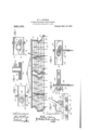
- Figure 1 represents a perspective view of my device.
- Fig. 2 is an enlarged detail of the lever and connections.
- Fig. 3 is an enlarged end view of a portion of the device, showing the method of securing the U- shaped bar.
- Fig. t is an enlarged front View of Fig. 3 showing the channel bars in section.
- Fig. 7 is an enlarged end perspective of a modification of Fig. 5.
- tooth bars may be rocked and the angular position of the teeth as a whole varied.
- the sections are secured to the draft bar in any desired manner, as, for instance, by means of chains secured to the ends of the end bars.
- the tooth bars are preferably U-shaped, and the teeth 12 fit in tooth clips 24 bolted to the bars.
- the end bars 11 are preferably formed from channel bars and used with the flanges 25 projecting outwardly. These bars are provided with a plurality of circular holes 26 through which the ends of the tooth bars pass.
- a tooth clip of special design is used contiguous to the end bar. That shown in Figs. 3 and 4t isprovided with an extended end 27.
- the end of the clip and the end of the bar are provided with openings registering with each other through which a cotter pin 28 is passed, the pin lying close against the bottom of the channel.
- the flanges 25 extend outwardly farther than the end 29 of the U-bar.
- a portion of the bottom of the tooth bar is out and turned outwardly forming a flange 30, while a corresponding lip or flange 31 is formed on the end of the tooth clip.
- the U-bar is slipped through the openings and the tooth clip also passed through the openings of the lips or flanges 31, fitting snugly against the bottom of the channel. The tooth clip is then bolted to the U- bar and this bar held against lateral movement.
- the end of the U-bar is slotted at 32 and a T- shaped lug 33 formed on the end of the tooth clip.
- the head 34 of the lug fits against the bottom of the channel bar and the end 35 fits within the slot 32 and also against the bottom of the channel bar.
- the U-bars are free to turn within the holes, but are given no opportunity for end-wise movement.
- a harrow comprising a frame, tooth bars, flanged end bars, said end bars formed from channel bars and provided with a series of holes through which the ends of said tooth bars project, and combined tooth holding and locking means for holding said tooth bars against lateral movement.
- a harrow comprising a frame, tooth bars, flanged end bars, said end bars formed from channel bars and provided with a series of holes through which the ends of said tooth bars project, tooth clips, end tooth clips, and teeth mounted thereon, and looking means integral with said end tooth clips for holding said tooth bars against lateral movement, the flanges of said channel bars forming a guard for the ends of said tooth bars.
- a harrow comprising a frame, tooth bars, tooth clips secured thereto, teeth fitting within said clips, end channel bars provided with a series of holes through which the ends WILLIAM E. JOHNSON.
Landscapes
- Life Sciences & Earth Sciences (AREA)
- Engineering & Computer Science (AREA)
- Mechanical Engineering (AREA)
- Soil Sciences (AREA)
- Environmental Sciences (AREA)
- Soil Working Implements (AREA)
Description
W. E. JOHNSON.
GUARDED END STEEL LEVEE HARROW.
APPLIOATIQN FILED SEPT. 10, 1908.
Patented Nov. 16, 1909.
UNITED sraras PATENT FFTCE.
WILLIAM E. JOHNSON, OF ROCK ISLAND, ILLINOIS, ASSIGNOR TO BOOK ISLAND PLOW COMPANY, OF ROCK ISLAND, ILLINOIS, A CORPORATION OF ILLINOIS.
GUARDED-END' STEEL-LEVER HARROW.
eaoaeo.
To all whom it may concern:
Be it known that I, lViLLIAM E. J OI-INSON, a citizen of the United States of America, and resident of Rock Island, Illinois, have invented a certain new and useful Improvement in Guarded-End Steel-Lever I-Iarrows, of which the following is a specification.
My invention relates to improvements in harrows, and has for its object the production of a device in which the ends of the harrow bars are protected from coming into contact with obstructions while in the field.
A. further object is the production of a device in which expensive castings for securing the harrow bars to the guard are dispensed with, and the wear thrown directly on the ends of the bars.
A further object is the production of improved means for securing the bars and guards in place.
A further object is the production of a de vice that is of simple construction, and one that is least liable to breakage and disarrangement of parts.
These and such other objects as may hereinafter appear are attained by my device, embodiments of which are illustrated in the accompanying drawings, in which Figure 1 represents a perspective view of my device. Fig. 2 is an enlarged detail of the lever and connections. Fig. 3 is an enlarged end view of a portion of the device, showing the method of securing the U- shaped bar. Fig. t is an enlarged front View of Fig. 3 showing the channel bars in section. Fig. 5 is an enlarged. end View showing amodification of Fig. Fig. 6 is an enlarged top plan View of Fig. 5. Fig. 7 is an enlarged end perspective of a modification of Fig. 5.
Like figures of reference indicate like parts in the several figures of the drawing.
Referring now to the drawings8 repre sents a draft bar; 9 the central frame bars, and 10 the tooth bars. 011 the ends of the tooth bars are secured end bars 11. Harrow teeth 12 are secured to the tooth bars and the angular position of the teeth with respect to the ground is varied through the medium of a lever bar 13 on which are pivotally mounted links 14. having squared openings in their opposite ends at 15 engaging the tooth bars. A rack 16 is mounted on this lever bar and a lever 17 is pivoted thereto at 18 and having an extended end 19 Specification of Letters Patent.
Application filed September 10, 1908.
Patented Nov. 16, 1909. Serial No. 452,391.
' provided with a slot 20. A bolt 21 passes through this slot and into the frame bar 9. It will thus be seen that by the operation of the lever the tooth bars may be rocked and the angular position of the teeth as a whole varied. The sections are secured to the draft bar in any desired manner, as, for instance, by means of chains secured to the ends of the end bars. The tooth bars are preferably U-shaped, and the teeth 12 fit in tooth clips 24 bolted to the bars.
The end bars 11 are preferably formed from channel bars and used with the flanges 25 projecting outwardly. These bars are provided with a plurality of circular holes 26 through which the ends of the tooth bars pass. In thev assembling of the device, a tooth clip of special design is used contiguous to the end bar. That shown in Figs. 3 and 4t isprovided with an extended end 27. The end of the clip and the end of the bar are provided with openings registering with each other through which a cotter pin 28 is passed, the pin lying close against the bottom of the channel. The flanges 25 extend outwardly farther than the end 29 of the U-bar.
In the modification shown in Figs. 5 and 6, a portion of the bottom of the tooth bar is out and turned outwardly forming a flange 30, while a corresponding lip or flange 31 is formed on the end of the tooth clip. In this form the U-bar is slipped through the openings and the tooth clip also passed through the openings of the lips or flanges 31, fitting snugly against the bottom of the channel. The tooth clip is then bolted to the U- bar and this bar held against lateral movement.
In the modification shown in Fig. 7 the end of the U-bar is slotted at 32 and a T- shaped lug 33 formed on the end of the tooth clip. In this form the head 34 of the lug fits against the bottom of the channel bar and the end 35 fits within the slot 32 and also against the bottom of the channel bar. In all of these forms the U-bars are free to turn within the holes, but are given no opportunity for end-wise movement.
By the use of my device, the use of all castings for holding the bars in place is dispensed with, and the wear thrown on the U-bar. This is a very important feature in implements of this class, as the castings are expensive and are easily broken, making it often necessary to send away for new cast= ings to replace the broken ones, and the implement is thrown out of commission. By the use of the channel bar with flanges of suflieient length to protect the ends of the U-bar, all danger of the ends of the bars catching in stumps, rocks, etc., is avoided.
This is an especially valuable feature when Working in orchards. I am aware that there are many ways in which the parts may be united and held firmly in position, but most of such means comprising a channel bar and harrow bar ends extending therethrough come within the scope of my invention.
I claim:
1. A harrow comprising a frame, tooth bars, flanged end bars, said end bars formed from channel bars and provided with a series of holes through which the ends of said tooth bars project, and combined tooth holding and locking means for holding said tooth bars against lateral movement.
2. A harrow comprising a frame, tooth bars, flanged end bars, said end bars formed from channel bars and provided with a series of holes through which the ends of said tooth bars project, tooth clips, end tooth clips, and teeth mounted thereon, and looking means integral with said end tooth clips for holding said tooth bars against lateral movement, the flanges of said channel bars forming a guard for the ends of said tooth bars.
3. A harrow comprising a frame, tooth bars, tooth clips secured thereto, teeth fitting within said clips, end channel bars provided with a series of holes through which the ends WILLIAM E. JOHNSON.
Witnesses:
A. B. FRENIER, H. DRTJENS.
Priority Applications (1)
| Application Number | Priority Date | Filing Date | Title |
|---|---|---|---|
| US45239108A US940160A (en) | 1908-09-10 | 1908-09-10 | Guarded-end steel-lever harrow. |
Applications Claiming Priority (1)
| Application Number | Priority Date | Filing Date | Title |
|---|---|---|---|
| US45239108A US940160A (en) | 1908-09-10 | 1908-09-10 | Guarded-end steel-lever harrow. |
Publications (1)
| Publication Number | Publication Date |
|---|---|
| US940160A true US940160A (en) | 1909-11-16 |
Family
ID=3008579
Family Applications (1)
| Application Number | Title | Priority Date | Filing Date |
|---|---|---|---|
| US45239108A Expired - Lifetime US940160A (en) | 1908-09-10 | 1908-09-10 | Guarded-end steel-lever harrow. |
Country Status (1)
| Country | Link |
|---|---|
| US (1) | US940160A (en) |
Cited By (1)
| Publication number | Priority date | Publication date | Assignee | Title |
|---|---|---|---|---|
| US2599492A (en) * | 1945-03-02 | 1952-06-03 | Case Co J I | Spike-tooth harrow |
-
1908
- 1908-09-10 US US45239108A patent/US940160A/en not_active Expired - Lifetime
Cited By (1)
| Publication number | Priority date | Publication date | Assignee | Title |
|---|---|---|---|---|
| US2599492A (en) * | 1945-03-02 | 1952-06-03 | Case Co J I | Spike-tooth harrow |
Similar Documents
| Publication | Publication Date | Title |
|---|---|---|
| US1204441A (en) | Grain-lifter for harvesters. | |
| US454825A (en) | Harrow | |
| US1167969A (en) | Combined drag and harrow. | |
| US197703A (en) | Improvement in harrow-teeth | |
| US323252A (en) | alexander | |
| US188871A (en) | Improvement in harrows | |
| US384966A (en) | Harrow | |
| US577038A (en) | Seymour johnson | |
| US1146476A (en) | Road-drag. | |
| US440047A (en) | Harrow | |
| US169853A (en) | Improvement in horse hay-rakes | |
| US1241033A (en) | Harrow. | |
| US485623A (en) | Harrow | |
| US476779A (en) | Plow-beam attachment | |
| US561643A (en) | bibcock | |
| US79042A (en) | Improvement in harrows | |
| US228382A (en) | Charles w- page | |
| USD21758S (en) | Design for a badge | |
| US739699A (en) | Harrow. | |
| US219882A (en) | Improvement in cultivajors | |
| US324480A (en) | Thomas pates | |
| US340301A (en) | Rotary colter | |
| US1102643A (en) | Triple offset for plows. | |
| US794850A (en) | Road-grader. | |
| US248461A (en) | Harrow |