US9385375B2 - Positive electrode for rechargeable lithium battery and rechargeable lithium battery including same - Google Patents
Positive electrode for rechargeable lithium battery and rechargeable lithium battery including same Download PDFInfo
- Publication number
- US9385375B2 US9385375B2 US14/057,766 US201314057766A US9385375B2 US 9385375 B2 US9385375 B2 US 9385375B2 US 201314057766 A US201314057766 A US 201314057766A US 9385375 B2 US9385375 B2 US 9385375B2
- Authority
- US
- United States
- Prior art keywords
- active material
- lithium battery
- rechargeable lithium
- positive active
- positive electrode
- Prior art date
- Legal status (The legal status is an assumption and is not a legal conclusion. Google has not performed a legal analysis and makes no representation as to the accuracy of the status listed.)
- Active, expires
Links
- 229910052744 lithium Inorganic materials 0.000 title claims abstract description 48
- WHXSMMKQMYFTQS-UHFFFAOYSA-N Lithium Chemical compound [Li] WHXSMMKQMYFTQS-UHFFFAOYSA-N 0.000 title claims abstract description 41
- 239000007774 positive electrode material Substances 0.000 claims abstract description 40
- 239000010410 layer Substances 0.000 claims abstract description 31
- 239000011247 coating layer Substances 0.000 claims abstract description 28
- 239000004020 conductor Substances 0.000 claims description 15
- 239000000126 substance Substances 0.000 claims description 11
- 239000011230 binding agent Substances 0.000 claims description 10
- 150000001875 compounds Chemical class 0.000 claims description 10
- 239000003792 electrolyte Substances 0.000 claims description 10
- 229910010119 LiAlTi(PO4) Inorganic materials 0.000 claims description 6
- 210000004027 cell Anatomy 0.000 description 23
- -1 chalcogenide compounds Chemical class 0.000 description 17
- 238000000576 coating method Methods 0.000 description 16
- 230000000052 comparative effect Effects 0.000 description 16
- 239000011248 coating agent Substances 0.000 description 15
- HBBGRARXTFLTSG-UHFFFAOYSA-N Lithium ion Chemical compound [Li+] HBBGRARXTFLTSG-UHFFFAOYSA-N 0.000 description 14
- 229910001416 lithium ion Inorganic materials 0.000 description 14
- PXHVJJICTQNCMI-UHFFFAOYSA-N nickel Substances [Ni] PXHVJJICTQNCMI-UHFFFAOYSA-N 0.000 description 14
- 239000000203 mixture Substances 0.000 description 13
- LFQSCWFLJHTTHZ-UHFFFAOYSA-N Ethanol Chemical compound CCO LFQSCWFLJHTTHZ-UHFFFAOYSA-N 0.000 description 11
- 239000007773 negative electrode material Substances 0.000 description 11
- 239000000463 material Substances 0.000 description 8
- 229910052751 metal Inorganic materials 0.000 description 8
- 239000002184 metal Substances 0.000 description 8
- 229910052759 nickel Inorganic materials 0.000 description 8
- 229910052782 aluminium Inorganic materials 0.000 description 7
- 230000014759 maintenance of location Effects 0.000 description 7
- 239000011572 manganese Substances 0.000 description 7
- 238000000034 method Methods 0.000 description 7
- MCMNRKCIXSYSNV-UHFFFAOYSA-N Zirconium dioxide Chemical compound O=[Zr]=O MCMNRKCIXSYSNV-UHFFFAOYSA-N 0.000 description 6
- 239000011149 active material Substances 0.000 description 6
- 238000011156 evaluation Methods 0.000 description 6
- 229910052748 manganese Inorganic materials 0.000 description 6
- 229910052720 vanadium Inorganic materials 0.000 description 6
- OKTJSMMVPCPJKN-UHFFFAOYSA-N Carbon Chemical group [C] OKTJSMMVPCPJKN-UHFFFAOYSA-N 0.000 description 5
- OIFBSDVPJOWBCH-UHFFFAOYSA-N Diethyl carbonate Chemical compound CCOC(=O)OCC OIFBSDVPJOWBCH-UHFFFAOYSA-N 0.000 description 5
- KMTRUDSVKNLOMY-UHFFFAOYSA-N Ethylene carbonate Chemical compound O=C1OCCO1 KMTRUDSVKNLOMY-UHFFFAOYSA-N 0.000 description 5
- 239000003575 carbonaceous material Substances 0.000 description 5
- 229910052804 chromium Inorganic materials 0.000 description 5
- 229910052802 copper Inorganic materials 0.000 description 5
- 239000010949 copper Substances 0.000 description 5
- 239000007788 liquid Substances 0.000 description 5
- 229910003002 lithium salt Inorganic materials 0.000 description 5
- 159000000002 lithium salts Chemical class 0.000 description 5
- 229910052749 magnesium Inorganic materials 0.000 description 5
- 238000004519 manufacturing process Methods 0.000 description 5
- 239000002904 solvent Substances 0.000 description 5
- RYGMFSIKBFXOCR-UHFFFAOYSA-N Copper Chemical compound [Cu] RYGMFSIKBFXOCR-UHFFFAOYSA-N 0.000 description 4
- 239000002033 PVDF binder Substances 0.000 description 4
- 239000004698 Polyethylene Substances 0.000 description 4
- 239000004743 Polypropylene Substances 0.000 description 4
- 229910045601 alloy Inorganic materials 0.000 description 4
- 239000000956 alloy Substances 0.000 description 4
- 239000002131 composite material Substances 0.000 description 4
- JBTWLSYIZRCDFO-UHFFFAOYSA-N ethyl methyl carbonate Chemical compound CCOC(=O)OC JBTWLSYIZRCDFO-UHFFFAOYSA-N 0.000 description 4
- 229910052742 iron Inorganic materials 0.000 description 4
- 238000002156 mixing Methods 0.000 description 4
- 239000011356 non-aqueous organic solvent Substances 0.000 description 4
- 229920000573 polyethylene Polymers 0.000 description 4
- 229920001155 polypropylene Polymers 0.000 description 4
- 229920001343 polytetrafluoroethylene Polymers 0.000 description 4
- 239000004810 polytetrafluoroethylene Substances 0.000 description 4
- 229920002981 polyvinylidene fluoride Polymers 0.000 description 4
- 239000007787 solid Substances 0.000 description 4
- 229910052712 strontium Inorganic materials 0.000 description 4
- KFZMGEQAYNKOFK-UHFFFAOYSA-N Isopropanol Chemical compound CC(C)O KFZMGEQAYNKOFK-UHFFFAOYSA-N 0.000 description 3
- 229910032387 LiCoO2 Inorganic materials 0.000 description 3
- 229910014063 LiNi1-xCoxO2 Inorganic materials 0.000 description 3
- 229910014402 LiNi1—xCoxO2 Inorganic materials 0.000 description 3
- 229910008557 LiaNi1-b-cCob Inorganic materials 0.000 description 3
- 229910014968 LiaNi1−b−cCob Inorganic materials 0.000 description 3
- SECXISVLQFMRJM-UHFFFAOYSA-N N-Methylpyrrolidone Chemical compound CN1CCCC1=O SECXISVLQFMRJM-UHFFFAOYSA-N 0.000 description 3
- VYPSYNLAJGMNEJ-UHFFFAOYSA-N Silicium dioxide Chemical compound O=[Si]=O VYPSYNLAJGMNEJ-UHFFFAOYSA-N 0.000 description 3
- XAGFODPZIPBFFR-UHFFFAOYSA-N aluminium Chemical compound [Al] XAGFODPZIPBFFR-UHFFFAOYSA-N 0.000 description 3
- 229910021383 artificial graphite Inorganic materials 0.000 description 3
- 229910052791 calcium Inorganic materials 0.000 description 3
- 239000008151 electrolyte solution Substances 0.000 description 3
- 239000000835 fiber Substances 0.000 description 3
- 238000009830 intercalation Methods 0.000 description 3
- 229910044991 metal oxide Inorganic materials 0.000 description 3
- 150000004706 metal oxides Chemical class 0.000 description 3
- 229910021382 natural graphite Inorganic materials 0.000 description 3
- 239000003960 organic solvent Substances 0.000 description 3
- 229910052698 phosphorus Inorganic materials 0.000 description 3
- 239000000843 powder Substances 0.000 description 3
- 229910052761 rare earth metal Inorganic materials 0.000 description 3
- 238000007086 side reaction Methods 0.000 description 3
- 229910052709 silver Inorganic materials 0.000 description 3
- 229910052718 tin Inorganic materials 0.000 description 3
- 239000010936 titanium Substances 0.000 description 3
- 229910052719 titanium Inorganic materials 0.000 description 3
- ZZXUZKXVROWEIF-UHFFFAOYSA-N 1,2-butylene carbonate Chemical compound CCC1COC(=O)O1 ZZXUZKXVROWEIF-UHFFFAOYSA-N 0.000 description 2
- YEJRWHAVMIAJKC-UHFFFAOYSA-N 4-Butyrolactone Chemical compound O=C1CCCO1 YEJRWHAVMIAJKC-UHFFFAOYSA-N 0.000 description 2
- OZJPLYNZGCXSJM-UHFFFAOYSA-N 5-valerolactone Chemical compound O=C1CCCCO1 OZJPLYNZGCXSJM-UHFFFAOYSA-N 0.000 description 2
- 229920000049 Carbon (fiber) Polymers 0.000 description 2
- 229920002134 Carboxymethyl cellulose Polymers 0.000 description 2
- RTZKZFJDLAIYFH-UHFFFAOYSA-N Diethyl ether Chemical compound CCOCC RTZKZFJDLAIYFH-UHFFFAOYSA-N 0.000 description 2
- PXGOKWXKJXAPGV-UHFFFAOYSA-N Fluorine Chemical compound FF PXGOKWXKJXAPGV-UHFFFAOYSA-N 0.000 description 2
- 229920002153 Hydroxypropyl cellulose Polymers 0.000 description 2
- 229910002993 LiMnO2 Inorganic materials 0.000 description 2
- 229910003005 LiNiO2 Inorganic materials 0.000 description 2
- 229910001290 LiPF6 Inorganic materials 0.000 description 2
- 229910008583 LiaNi1-b-cMnb Inorganic materials 0.000 description 2
- 229910014615 LiaNi1−b−cMnb Inorganic materials 0.000 description 2
- WMFOQBRAJBCJND-UHFFFAOYSA-M Lithium hydroxide Chemical compound [Li+].[OH-] WMFOQBRAJBCJND-UHFFFAOYSA-M 0.000 description 2
- 229910002097 Lithium manganese(III,IV) oxide Inorganic materials 0.000 description 2
- 239000004677 Nylon Substances 0.000 description 2
- OAICVXFJPJFONN-UHFFFAOYSA-N Phosphorus Chemical compound [P] OAICVXFJPJFONN-UHFFFAOYSA-N 0.000 description 2
- 229920003171 Poly (ethylene oxide) Polymers 0.000 description 2
- 229920000265 Polyparaphenylene Polymers 0.000 description 2
- 239000004372 Polyvinyl alcohol Substances 0.000 description 2
- BQCADISMDOOEFD-UHFFFAOYSA-N Silver Chemical compound [Ag] BQCADISMDOOEFD-UHFFFAOYSA-N 0.000 description 2
- NINIDFKCEFEMDL-UHFFFAOYSA-N Sulfur Chemical compound [S] NINIDFKCEFEMDL-UHFFFAOYSA-N 0.000 description 2
- WYURNTSHIVDZCO-UHFFFAOYSA-N Tetrahydrofuran Chemical compound C1CCOC1 WYURNTSHIVDZCO-UHFFFAOYSA-N 0.000 description 2
- GWEVSGVZZGPLCZ-UHFFFAOYSA-N Titan oxide Chemical compound O=[Ti]=O GWEVSGVZZGPLCZ-UHFFFAOYSA-N 0.000 description 2
- 239000006230 acetylene black Substances 0.000 description 2
- 229920005993 acrylate styrene-butadiene rubber polymer Polymers 0.000 description 2
- 239000005456 alcohol based solvent Substances 0.000 description 2
- 229910052783 alkali metal Inorganic materials 0.000 description 2
- 150000001340 alkali metals Chemical class 0.000 description 2
- 229910052784 alkaline earth metal Inorganic materials 0.000 description 2
- 150000001342 alkaline earth metals Chemical class 0.000 description 2
- 229910003481 amorphous carbon Inorganic materials 0.000 description 2
- 229910052785 arsenic Inorganic materials 0.000 description 2
- 229910052796 boron Inorganic materials 0.000 description 2
- 229910052799 carbon Inorganic materials 0.000 description 2
- 239000004917 carbon fiber Substances 0.000 description 2
- 239000003660 carbonate based solvent Substances 0.000 description 2
- 239000005466 carboxylated polyvinylchloride Substances 0.000 description 2
- 229910052798 chalcogen Inorganic materials 0.000 description 2
- 230000008859 change Effects 0.000 description 2
- JHIVVAPYMSGYDF-UHFFFAOYSA-N cyclohexanone Chemical compound O=C1CCCCC1 JHIVVAPYMSGYDF-UHFFFAOYSA-N 0.000 description 2
- 238000009831 deintercalation Methods 0.000 description 2
- IEJIGPNLZYLLBP-UHFFFAOYSA-N dimethyl carbonate Chemical compound COC(=O)OC IEJIGPNLZYLLBP-UHFFFAOYSA-N 0.000 description 2
- VUPKGFBOKBGHFZ-UHFFFAOYSA-N dipropyl carbonate Chemical compound CCCOC(=O)OCCC VUPKGFBOKBGHFZ-UHFFFAOYSA-N 0.000 description 2
- 230000000694 effects Effects 0.000 description 2
- 239000003822 epoxy resin Substances 0.000 description 2
- 239000003759 ester based solvent Substances 0.000 description 2
- FKRCODPIKNYEAC-UHFFFAOYSA-N ethyl propionate Chemical compound CCOC(=O)CC FKRCODPIKNYEAC-UHFFFAOYSA-N 0.000 description 2
- QKBJDEGZZJWPJA-UHFFFAOYSA-N ethyl propyl carbonate Chemical compound [CH2]COC(=O)OCCC QKBJDEGZZJWPJA-UHFFFAOYSA-N 0.000 description 2
- 239000011737 fluorine Substances 0.000 description 2
- 229910052731 fluorine Inorganic materials 0.000 description 2
- 239000006260 foam Substances 0.000 description 2
- 239000011888 foil Substances 0.000 description 2
- 229910052733 gallium Inorganic materials 0.000 description 2
- 229910052732 germanium Inorganic materials 0.000 description 2
- XLYOFNOQVPJJNP-UHFFFAOYSA-M hydroxide Chemical compound [OH-] XLYOFNOQVPJJNP-UHFFFAOYSA-M 0.000 description 2
- 239000001863 hydroxypropyl cellulose Substances 0.000 description 2
- 235000010977 hydroxypropyl cellulose Nutrition 0.000 description 2
- 229910052738 indium Inorganic materials 0.000 description 2
- 230000002687 intercalation Effects 0.000 description 2
- 150000002500 ions Chemical class 0.000 description 2
- 239000003273 ketjen black Substances 0.000 description 2
- 239000005453 ketone based solvent Substances 0.000 description 2
- 229910052745 lead Inorganic materials 0.000 description 2
- KWGKDLIKAYFUFQ-UHFFFAOYSA-M lithium chloride Chemical compound [Li+].[Cl-] KWGKDLIKAYFUFQ-UHFFFAOYSA-M 0.000 description 2
- VNWKTOKETHGBQD-UHFFFAOYSA-N methane Chemical compound C VNWKTOKETHGBQD-UHFFFAOYSA-N 0.000 description 2
- KKQAVHGECIBFRQ-UHFFFAOYSA-N methyl propyl carbonate Chemical compound CCCOC(=O)OC KKQAVHGECIBFRQ-UHFFFAOYSA-N 0.000 description 2
- 229910052750 molybdenum Inorganic materials 0.000 description 2
- 229920001778 nylon Polymers 0.000 description 2
- 239000002245 particle Substances 0.000 description 2
- 239000011574 phosphorus Substances 0.000 description 2
- 229920000647 polyepoxide Polymers 0.000 description 2
- 229920002635 polyurethane Polymers 0.000 description 2
- 239000004814 polyurethane Substances 0.000 description 2
- 229920002451 polyvinyl alcohol Polymers 0.000 description 2
- 229920000915 polyvinyl chloride Polymers 0.000 description 2
- 239000004800 polyvinyl chloride Substances 0.000 description 2
- 229920002620 polyvinyl fluoride Polymers 0.000 description 2
- 229920000973 polyvinylchloride carboxylated Polymers 0.000 description 2
- 229920000036 polyvinylpyrrolidone Polymers 0.000 description 2
- 239000001267 polyvinylpyrrolidone Substances 0.000 description 2
- 235000013855 polyvinylpyrrolidone Nutrition 0.000 description 2
- 229910052700 potassium Inorganic materials 0.000 description 2
- 230000008569 process Effects 0.000 description 2
- YKYONYBAUNKHLG-UHFFFAOYSA-N propyl acetate Chemical compound CCCOC(C)=O YKYONYBAUNKHLG-UHFFFAOYSA-N 0.000 description 2
- RUOJZAUFBMNUDX-UHFFFAOYSA-N propylene carbonate Chemical compound CC1COC(=O)O1 RUOJZAUFBMNUDX-UHFFFAOYSA-N 0.000 description 2
- 229910052706 scandium Inorganic materials 0.000 description 2
- 239000004332 silver Substances 0.000 description 2
- 238000005245 sintering Methods 0.000 description 2
- 229910052708 sodium Inorganic materials 0.000 description 2
- 229920003048 styrene butadiene rubber Polymers 0.000 description 2
- 229910052717 sulfur Inorganic materials 0.000 description 2
- 239000011593 sulfur Substances 0.000 description 2
- XOLBLPGZBRYERU-UHFFFAOYSA-N tin dioxide Chemical compound O=[Sn]=O XOLBLPGZBRYERU-UHFFFAOYSA-N 0.000 description 2
- 230000007704 transition Effects 0.000 description 2
- 229910000314 transition metal oxide Inorganic materials 0.000 description 2
- 229910052727 yttrium Inorganic materials 0.000 description 2
- 229910052725 zinc Inorganic materials 0.000 description 2
- 229910052726 zirconium Inorganic materials 0.000 description 2
- JYVXNLLUYHCIIH-UHFFFAOYSA-N (+/-)-mevalonolactone Natural products CC1(O)CCOC(=O)C1 JYVXNLLUYHCIIH-UHFFFAOYSA-N 0.000 description 1
- DURPTKYDGMDSBL-UHFFFAOYSA-N 1-butoxybutane Chemical compound CCCCOCCCC DURPTKYDGMDSBL-UHFFFAOYSA-N 0.000 description 1
- JWUJQDFVADABEY-UHFFFAOYSA-N 2-methyltetrahydrofuran Chemical compound CC1CCCO1 JWUJQDFVADABEY-UHFFFAOYSA-N 0.000 description 1
- BTBUEUYNUDRHOZ-UHFFFAOYSA-N Borate Chemical compound [O-]B([O-])[O-] BTBUEUYNUDRHOZ-UHFFFAOYSA-N 0.000 description 1
- 239000006245 Carbon black Super-P Substances 0.000 description 1
- BVKZGUZCCUSVTD-UHFFFAOYSA-L Carbonate Chemical compound [O-]C([O-])=O BVKZGUZCCUSVTD-UHFFFAOYSA-L 0.000 description 1
- 229910052684 Cerium Inorganic materials 0.000 description 1
- 229910021503 Cobalt(II) hydroxide Inorganic materials 0.000 description 1
- XTHFKEDIFFGKHM-UHFFFAOYSA-N Dimethoxyethane Chemical compound COCCOC XTHFKEDIFFGKHM-UHFFFAOYSA-N 0.000 description 1
- XEKOWRVHYACXOJ-UHFFFAOYSA-N Ethyl acetate Chemical compound CCOC(C)=O XEKOWRVHYACXOJ-UHFFFAOYSA-N 0.000 description 1
- 229910010092 LiAlO2 Inorganic materials 0.000 description 1
- 229910013188 LiBOB Inorganic materials 0.000 description 1
- 229910001559 LiC4F9SO3 Inorganic materials 0.000 description 1
- 229910052493 LiFePO4 Inorganic materials 0.000 description 1
- 229910021447 LiN(CxF2x+1SO2)(CyF2y+1SO2) Inorganic materials 0.000 description 1
- 229910013417 LiN(SO3C2F5)2 Inorganic materials 0.000 description 1
- 229910013124 LiNiVO4 Inorganic materials 0.000 description 1
- 229910021466 LiQS2 Inorganic materials 0.000 description 1
- 229910012946 LiV2O5 Inorganic materials 0.000 description 1
- 229910021462 LiaCoGbO2 Inorganic materials 0.000 description 1
- 229910021464 LiaMn2GbO4 Inorganic materials 0.000 description 1
- 229910008524 LiaN1-b-cMnb Inorganic materials 0.000 description 1
- 229910021461 LiaNiGbO2 Inorganic materials 0.000 description 1
- 229910021460 LiaNibCocMndGeO2 Inorganic materials 0.000 description 1
- 229910021459 LiaNibEcGdO2 Inorganic materials 0.000 description 1
- RJUFJBKOKNCXHH-UHFFFAOYSA-N Methyl propionate Chemical compound CCC(=O)OC RJUFJBKOKNCXHH-UHFFFAOYSA-N 0.000 description 1
- JYVXNLLUYHCIIH-ZCFIWIBFSA-N R-mevalonolactone, (-)- Chemical compound C[C@@]1(O)CCOC(=O)C1 JYVXNLLUYHCIIH-ZCFIWIBFSA-N 0.000 description 1
- 229910006772 Si—Y1 Inorganic materials 0.000 description 1
- 229910008862 Sn—Y1 Inorganic materials 0.000 description 1
- RTAQQCXQSZGOHL-UHFFFAOYSA-N Titanium Chemical compound [Ti] RTAQQCXQSZGOHL-UHFFFAOYSA-N 0.000 description 1
- RLTFLELMPUMVEH-UHFFFAOYSA-N [Li+].[O--].[O--].[O--].[V+5] Chemical compound [Li+].[O--].[O--].[O--].[V+5] RLTFLELMPUMVEH-UHFFFAOYSA-N 0.000 description 1
- XHCLAFWTIXFWPH-UHFFFAOYSA-N [O-2].[O-2].[O-2].[O-2].[O-2].[V+5].[V+5] Chemical compound [O-2].[O-2].[O-2].[O-2].[O-2].[V+5].[V+5] XHCLAFWTIXFWPH-UHFFFAOYSA-N 0.000 description 1
- 239000000654 additive Substances 0.000 description 1
- 230000000996 additive effect Effects 0.000 description 1
- PNEYBMLMFCGWSK-UHFFFAOYSA-N aluminium oxide Inorganic materials [O-2].[O-2].[O-2].[Al+3].[Al+3] PNEYBMLMFCGWSK-UHFFFAOYSA-N 0.000 description 1
- 229910052787 antimony Inorganic materials 0.000 description 1
- 239000000010 aprotic solvent Substances 0.000 description 1
- QVGXLLKOCUKJST-UHFFFAOYSA-N atomic oxygen Chemical compound [O] QVGXLLKOCUKJST-UHFFFAOYSA-N 0.000 description 1
- 230000008901 benefit Effects 0.000 description 1
- 229910052790 beryllium Inorganic materials 0.000 description 1
- 230000015572 biosynthetic process Effects 0.000 description 1
- 229910021475 bohrium Inorganic materials 0.000 description 1
- 229910052793 cadmium Inorganic materials 0.000 description 1
- 229910052792 caesium Inorganic materials 0.000 description 1
- 150000004649 carbonic acid derivatives Chemical class 0.000 description 1
- 238000003763 carbonization Methods 0.000 description 1
- NKCVNYJQLIWBHK-UHFFFAOYSA-N carbonodiperoxoic acid Chemical compound OOC(=O)OO NKCVNYJQLIWBHK-UHFFFAOYSA-N 0.000 description 1
- ZFTFAPZRGNKQPU-UHFFFAOYSA-L carboxylato carbonate Chemical compound [O-]C(=O)OC([O-])=O ZFTFAPZRGNKQPU-UHFFFAOYSA-L 0.000 description 1
- 239000000919 ceramic Substances 0.000 description 1
- 239000003610 charcoal Substances 0.000 description 1
- 229910017052 cobalt Inorganic materials 0.000 description 1
- 239000010941 cobalt Substances 0.000 description 1
- GUTLYIVDDKVIGB-UHFFFAOYSA-N cobalt atom Chemical compound [Co] GUTLYIVDDKVIGB-UHFFFAOYSA-N 0.000 description 1
- 229910052681 coesite Inorganic materials 0.000 description 1
- 229920001940 conductive polymer Polymers 0.000 description 1
- 239000011889 copper foil Substances 0.000 description 1
- 238000012937 correction Methods 0.000 description 1
- 229910052593 corundum Inorganic materials 0.000 description 1
- 229910052906 cristobalite Inorganic materials 0.000 description 1
- 150000005676 cyclic carbonates Chemical class 0.000 description 1
- 230000006378 damage Effects 0.000 description 1
- 230000003247 decreasing effect Effects 0.000 description 1
- 210000001787 dendrite Anatomy 0.000 description 1
- 229920005994 diacetyl cellulose Polymers 0.000 description 1
- MNNHAPBLZZVQHP-UHFFFAOYSA-N diammonium hydrogen phosphate Chemical compound [NH4+].[NH4+].OP([O-])([O-])=O MNNHAPBLZZVQHP-UHFFFAOYSA-N 0.000 description 1
- 229910000388 diammonium phosphate Inorganic materials 0.000 description 1
- SBZXBUIDTXKZTM-UHFFFAOYSA-N diglyme Chemical compound COCCOCCOC SBZXBUIDTXKZTM-UHFFFAOYSA-N 0.000 description 1
- 238000007599 discharging Methods 0.000 description 1
- 238000003487 electrochemical reaction Methods 0.000 description 1
- 238000005516 engineering process Methods 0.000 description 1
- 239000004210 ether based solvent Substances 0.000 description 1
- 238000001914 filtration Methods 0.000 description 1
- 239000011326 fired coke Substances 0.000 description 1
- 238000010304 firing Methods 0.000 description 1
- 229910052730 francium Inorganic materials 0.000 description 1
- 239000003365 glass fiber Substances 0.000 description 1
- 229910052737 gold Inorganic materials 0.000 description 1
- 229910052735 hafnium Inorganic materials 0.000 description 1
- 229910021385 hard carbon Inorganic materials 0.000 description 1
- 229910021473 hassium Inorganic materials 0.000 description 1
- 238000010438 heat treatment Methods 0.000 description 1
- 238000005470 impregnation Methods 0.000 description 1
- 238000010348 incorporation Methods 0.000 description 1
- 239000003112 inhibitor Substances 0.000 description 1
- 229910052741 iridium Inorganic materials 0.000 description 1
- KQNPFQTWMSNSAP-UHFFFAOYSA-N isobutyric acid Chemical compound CC(C)C(O)=O KQNPFQTWMSNSAP-UHFFFAOYSA-N 0.000 description 1
- 229910052746 lanthanum Inorganic materials 0.000 description 1
- XGZVUEUWXADBQD-UHFFFAOYSA-L lithium carbonate Chemical compound [Li+].[Li+].[O-]C([O-])=O XGZVUEUWXADBQD-UHFFFAOYSA-L 0.000 description 1
- 229910052808 lithium carbonate Inorganic materials 0.000 description 1
- 229910001547 lithium hexafluoroantimonate(V) Inorganic materials 0.000 description 1
- 229910001540 lithium hexafluoroarsenate(V) Inorganic materials 0.000 description 1
- MHCFAGZWMAWTNR-UHFFFAOYSA-M lithium perchlorate Chemical compound [Li+].[O-]Cl(=O)(=O)=O MHCFAGZWMAWTNR-UHFFFAOYSA-M 0.000 description 1
- 229910001486 lithium perchlorate Inorganic materials 0.000 description 1
- 229910001537 lithium tetrachloroaluminate Inorganic materials 0.000 description 1
- 229910001496 lithium tetrafluoroborate Inorganic materials 0.000 description 1
- 229910000686 lithium vanadium oxide Inorganic materials 0.000 description 1
- WPBNNNQJVZRUHP-UHFFFAOYSA-L manganese(2+);methyl n-[[2-(methoxycarbonylcarbamothioylamino)phenyl]carbamothioyl]carbamate;n-[2-(sulfidocarbothioylamino)ethyl]carbamodithioate Chemical compound [Mn+2].[S-]C(=S)NCCNC([S-])=S.COC(=O)NC(=S)NC1=CC=CC=C1NC(=S)NC(=O)OC WPBNNNQJVZRUHP-UHFFFAOYSA-L 0.000 description 1
- 239000011302 mesophase pitch Substances 0.000 description 1
- 239000007769 metal material Substances 0.000 description 1
- KXKVLQRXCPHEJC-UHFFFAOYSA-N methyl acetate Chemical compound COC(C)=O KXKVLQRXCPHEJC-UHFFFAOYSA-N 0.000 description 1
- 229940017219 methyl propionate Drugs 0.000 description 1
- 229940057061 mevalonolactone Drugs 0.000 description 1
- 239000011259 mixed solution Substances 0.000 description 1
- 238000012986 modification Methods 0.000 description 1
- 230000004048 modification Effects 0.000 description 1
- 230000007935 neutral effect Effects 0.000 description 1
- 229910021508 nickel(II) hydroxide Inorganic materials 0.000 description 1
- 229910052758 niobium Inorganic materials 0.000 description 1
- 239000011255 nonaqueous electrolyte Substances 0.000 description 1
- 239000004745 nonwoven fabric Substances 0.000 description 1
- 239000005486 organic electrolyte Substances 0.000 description 1
- 229910052762 osmium Inorganic materials 0.000 description 1
- GHZRKQCHJFHJPX-UHFFFAOYSA-N oxacycloundecan-2-one Chemical compound O=C1CCCCCCCCCO1 GHZRKQCHJFHJPX-UHFFFAOYSA-N 0.000 description 1
- 229910052760 oxygen Inorganic materials 0.000 description 1
- 239000001301 oxygen Substances 0.000 description 1
- 229910052763 palladium Inorganic materials 0.000 description 1
- 229910052697 platinum Inorganic materials 0.000 description 1
- 229910052699 polonium Inorganic materials 0.000 description 1
- 229920000728 polyester Polymers 0.000 description 1
- 229920000642 polymer Polymers 0.000 description 1
- 239000005518 polymer electrolyte Substances 0.000 description 1
- 239000002861 polymer material Substances 0.000 description 1
- 229920000307 polymer substrate Polymers 0.000 description 1
- 229920000098 polyolefin Polymers 0.000 description 1
- 238000002360 preparation method Methods 0.000 description 1
- 238000010298 pulverizing process Methods 0.000 description 1
- 239000000376 reactant Substances 0.000 description 1
- 230000009467 reduction Effects 0.000 description 1
- 238000011160 research Methods 0.000 description 1
- 229910052702 rhenium Inorganic materials 0.000 description 1
- 229910052703 rhodium Inorganic materials 0.000 description 1
- 229910052701 rubidium Inorganic materials 0.000 description 1
- 229910052707 ruthenium Inorganic materials 0.000 description 1
- 229910021481 rutherfordium Inorganic materials 0.000 description 1
- 150000003839 salts Chemical class 0.000 description 1
- 229910021477 seaborgium Inorganic materials 0.000 description 1
- 238000007789 sealing Methods 0.000 description 1
- 229910052711 selenium Inorganic materials 0.000 description 1
- 229910052710 silicon Inorganic materials 0.000 description 1
- 239000000377 silicon dioxide Substances 0.000 description 1
- 229910052814 silicon oxide Inorganic materials 0.000 description 1
- 239000002153 silicon-carbon composite material Substances 0.000 description 1
- 229910021384 soft carbon Inorganic materials 0.000 description 1
- 238000003746 solid phase reaction Methods 0.000 description 1
- 238000005507 spraying Methods 0.000 description 1
- 239000010935 stainless steel Substances 0.000 description 1
- 229910001220 stainless steel Inorganic materials 0.000 description 1
- 229910052682 stishovite Inorganic materials 0.000 description 1
- 229910052713 technetium Inorganic materials 0.000 description 1
- 229910052714 tellurium Inorganic materials 0.000 description 1
- ZUHZGEOKBKGPSW-UHFFFAOYSA-N tetraglyme Chemical compound COCCOCCOCCOCCOC ZUHZGEOKBKGPSW-UHFFFAOYSA-N 0.000 description 1
- YLQBMQCUIZJEEH-UHFFFAOYSA-N tetrahydrofuran Natural products C=1C=COC=1 YLQBMQCUIZJEEH-UHFFFAOYSA-N 0.000 description 1
- 229910052716 thallium Inorganic materials 0.000 description 1
- 239000002733 tin-carbon composite material Substances 0.000 description 1
- 238000012546 transfer Methods 0.000 description 1
- 229910052905 tridymite Inorganic materials 0.000 description 1
- 229910052721 tungsten Inorganic materials 0.000 description 1
- 229910001935 vanadium oxide Inorganic materials 0.000 description 1
- 239000002759 woven fabric Substances 0.000 description 1
- 229910001845 yogo sapphire Inorganic materials 0.000 description 1
- PAPBSGBWRJIAAV-UHFFFAOYSA-N ε-Caprolactone Chemical compound O=C1CCCCCO1 PAPBSGBWRJIAAV-UHFFFAOYSA-N 0.000 description 1
Images


Classifications
-
- H—ELECTRICITY
- H01—ELECTRIC ELEMENTS
- H01M—PROCESSES OR MEANS, e.g. BATTERIES, FOR THE DIRECT CONVERSION OF CHEMICAL ENERGY INTO ELECTRICAL ENERGY
- H01M4/00—Electrodes
- H01M4/02—Electrodes composed of, or comprising, active material
- H01M4/62—Selection of inactive substances as ingredients for active masses, e.g. binders, fillers
- H01M4/628—Inhibitors, e.g. gassing inhibitors, corrosion inhibitors
-
- C—CHEMISTRY; METALLURGY
- C01—INORGANIC CHEMISTRY
- C01B—NON-METALLIC ELEMENTS; COMPOUNDS THEREOF; METALLOIDS OR COMPOUNDS THEREOF NOT COVERED BY SUBCLASS C01C
- C01B25/00—Phosphorus; Compounds thereof
- C01B25/16—Oxyacids of phosphorus; Salts thereof
- C01B25/26—Phosphates
- C01B25/45—Phosphates containing plural metal, or metal and ammonium
-
- H—ELECTRICITY
- H01—ELECTRIC ELEMENTS
- H01M—PROCESSES OR MEANS, e.g. BATTERIES, FOR THE DIRECT CONVERSION OF CHEMICAL ENERGY INTO ELECTRICAL ENERGY
- H01M4/00—Electrodes
- H01M4/02—Electrodes composed of, or comprising, active material
- H01M4/13—Electrodes for accumulators with non-aqueous electrolyte, e.g. for lithium-accumulators; Processes of manufacture thereof
- H01M4/131—Electrodes based on mixed oxides or hydroxides, or on mixtures of oxides or hydroxides, e.g. LiCoOx
-
- H—ELECTRICITY
- H01—ELECTRIC ELEMENTS
- H01M—PROCESSES OR MEANS, e.g. BATTERIES, FOR THE DIRECT CONVERSION OF CHEMICAL ENERGY INTO ELECTRICAL ENERGY
- H01M4/00—Electrodes
- H01M4/02—Electrodes composed of, or comprising, active material
- H01M4/36—Selection of substances as active materials, active masses, active liquids
- H01M4/362—Composites
- H01M4/366—Composites as layered products
-
- H—ELECTRICITY
- H01—ELECTRIC ELEMENTS
- H01M—PROCESSES OR MEANS, e.g. BATTERIES, FOR THE DIRECT CONVERSION OF CHEMICAL ENERGY INTO ELECTRICAL ENERGY
- H01M4/00—Electrodes
- H01M4/02—Electrodes composed of, or comprising, active material
- H01M4/36—Selection of substances as active materials, active masses, active liquids
- H01M4/58—Selection of substances as active materials, active masses, active liquids of inorganic compounds other than oxides or hydroxides, e.g. sulfides, selenides, tellurides, halogenides or LiCoFy; of polyanionic structures, e.g. phosphates, silicates or borates
- H01M4/5825—Oxygenated metallic salts or polyanionic structures, e.g. borates, phosphates, silicates, olivines
-
- H—ELECTRICITY
- H01—ELECTRIC ELEMENTS
- H01M—PROCESSES OR MEANS, e.g. BATTERIES, FOR THE DIRECT CONVERSION OF CHEMICAL ENERGY INTO ELECTRICAL ENERGY
- H01M10/00—Secondary cells; Manufacture thereof
- H01M10/05—Accumulators with non-aqueous electrolyte
- H01M10/052—Li-accumulators
- H01M10/0525—Rocking-chair batteries, i.e. batteries with lithium insertion or intercalation in both electrodes; Lithium-ion batteries
-
- Y—GENERAL TAGGING OF NEW TECHNOLOGICAL DEVELOPMENTS; GENERAL TAGGING OF CROSS-SECTIONAL TECHNOLOGIES SPANNING OVER SEVERAL SECTIONS OF THE IPC; TECHNICAL SUBJECTS COVERED BY FORMER USPC CROSS-REFERENCE ART COLLECTIONS [XRACs] AND DIGESTS
- Y02—TECHNOLOGIES OR APPLICATIONS FOR MITIGATION OR ADAPTATION AGAINST CLIMATE CHANGE
- Y02E—REDUCTION OF GREENHOUSE GAS [GHG] EMISSIONS, RELATED TO ENERGY GENERATION, TRANSMISSION OR DISTRIBUTION
- Y02E60/00—Enabling technologies; Technologies with a potential or indirect contribution to GHG emissions mitigation
- Y02E60/10—Energy storage using batteries
-
- Y02E60/122—
Definitions
- This disclosure relates to a positive electrode for a rechargeable lithium battery and a rechargeable lithium battery including the same.
- a rechargeable lithium battery is manufactured using materials for negative and positive electrodes that intercalate or deintercalate lithium ions, and filing an organic electrolyte solution or a polymer electrolyte that transfer lithium ions between the positive and negative electrodes.
- a rechargeable lithium battery may use a lithium metal as a negative active material, but dendrite formation on the surface of the lithium metal during charge and discharge is possible and may cause a battery short circuit and battery destruction.
- a carbon-based material reversibly receiving and supplying lithium ions as well as maintaining a structure and electric property and having a similar half-cell potential to a lithium metal during intercalation/deintercalation of lithium ions has been widely used as a negative active material.
- metal chalcogenide compounds being capable of intercalating and deintercalating lithium ions, and for example, composite metal oxide such as LiCoO 2 , LiMn 2 O 4 , LiNiO 2 , LiNi 1 ⁇ x Co x O 2 (0 ⁇ x ⁇ 1), LiMnO 2 , and the like has been used.
- LiNiO 2 among the positive active materials has high charge capacity but is difficult to synthesize, while a Mn-based active material such as LiMn 2 O 4 , LiMnO 2 , and the like is easy to synthesize, and relatively inexpensive but have relatively small capacity.
- the LiCoO 2 shows electrical conductivity of about 10 ⁇ 2 S/cm to 1 S/cm at room temperature, high battery voltage, and excellent electrode characteristics and thus, has been widely used but has low stability during high-rate charge and discharge.
- these composite metal oxides are prepared in a solid-phase reaction method of mixing raw powders in a solid state and firing the mixture.
- LiNi 1 ⁇ x Co x O 2 (0 ⁇ x ⁇ 1) may be prepared by mixing Ni(OH) 2 with Co(OH) 2 or hydroxide containing Ni and Co, then, heat-treating, pulverizing, and filtering LiNi 1 ⁇ x Co x O 2 (0 ⁇ x ⁇ 1) using sieves, and the like.
- Another method of preparing composite metal oxides includes forming a crystalline active material by reacting LiOH, Ni oxide, and Co oxide, primarily sintering the reactant to form an initial oxide at 400° C. to 580° C., and secondarily sintering the initial oxide at 600° C. to 780° C.
- the active materials prepared using the above methods When active materials prepared using the above methods are used to manufacture a rechargeable lithium battery, the active materials may not maintain main characteristics of the rechargeable lithium battery at a high voltage due to a side reaction with an electrolyte and the like.
- One embodiment provides a positive electrode for a rechargeable lithium battery that has excellent high-rate charge and discharge characteristics and cycle-life characteristics as well as high safety.
- Another embodiment provides a rechargeable lithium battery including the positive electrode for a rechargeable lithium battery.
- a positive electrode for a rechargeable lithium battery includes a current collector, a positive active material layer disposed on the current collector, and a coating layer disposed on the positive active material layer, wherein the coating layer includes a compound represented by Chemical Formula 1. Li a Al b Ti c (PO 4 ) d Chemical Formula 1
- a, b, c and d may be in the following ranges: 0.6 ⁇ a ⁇ 1.2, 0.5 ⁇ b ⁇ 1.2, 0.8 ⁇ c ⁇ 1.6, and 0.5 ⁇ d ⁇ 2.0.
- the coating layer may be included in an amount of about 0.1 parts to about 1 part by weight based on 100 parts by weight of the positive active material layer.
- the positive active material layer may include a positive active material, a conductive material, and a binder.
- a rechargeable lithium battery includes the positive electrode, a negative electrode, and an electrolyte.
- the coating layer includes a compound represented by Chemical Formula 1.
- the coating layer is included in an amount of about 0.1 parts to about 1 part by weight based on 100 parts by weight of the positive active material layer.
- the positive active material layer comprises a positive active material, a conductive material, and a binder.
- the coating layer includes LiAlTi(PO 4 ).
- the positive electrode according to one embodiment may realize a rechargeable lithium battery having excellent high-rate charge and discharge characteristics and cycle-life characteristics as well as high safety.
- FIG. 1 is a schematic view showing a rechargeable lithium battery according to one embodiment.
- FIG. 2 is a graph showing charge/discharge specific capacity at room temperature (25° C.) of the cells according to Example 1 and Comparative Example 1.
- FIG. 3 is a graph showing charge/discharge specific capacity at a high temperature (60° C.) of the cells according to Example 1 and Comparative Example 1.
- FIG. 4 is a graph showing capacity retention depending on a cycle at room temperature (25° C.) of the cells according to Example 1 and Comparative Example 1.
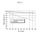
- FIG. 5 is a graph showing capacity retention depending on a cycle at a high temperature (60° C.) of the cells according to Example 1 and Comparative Example 1.
- a positive electrode for a rechargeable lithium battery includes a current collector, a positive active material layer disposed on the current collector, and a coating layer disposed on the positive active material layer, wherein the coating layer includes a compound represented by Chemical Formula 1. Li a Al b Ti c (PO 4 ) d Chemical Formula 1
- the coating layer including the compound represented by the above Chemical Formula 1 coats the positive active material layer, and thus prevents the positive active material layer from contacting an electrolyte directly. Therefore, a side reaction caused by direct contact of the positive active material layer with an electrolyte may be suppressed, and thereby battery characteristics may be improved.
- the a, b, c and d may be in the following ranges: 0.1 ⁇ a ⁇ 1.2, 0.35 ⁇ b ⁇ 1.2, 0.1 ⁇ c ⁇ 1.6, and 0.1 ⁇ d ⁇ 2.9, specifically 0.6 ⁇ a ⁇ 1.2, 0.5 ⁇ b ⁇ 1.2, 0.8 ⁇ c ⁇ 1.6 and 0.5 ⁇ d ⁇ 2.0, and more specifically 1.0 ⁇ a ⁇ 1.2, 1.0 ⁇ b ⁇ 1.2, 1.0 ⁇ c ⁇ 1.6 and 1.0 ⁇ d ⁇ 2.0.
- a, b, c, and d when a, b, c, and d are within the range, optimal electrochemical effects and particularly, excellent high-rate charge and discharge characteristics and cycle-life characteristics at a high voltage and a high temperature may be obtained.
- the coating layer may be included in an amount of about 0.1 parts to about 1 part by weight and specifically about 0.1 parts to about 0.5 parts by weight based on 100 parts by weight of the positive active material layer. When the coating layer is included within the range, discharge capacity of a rechargeable lithium battery may be maximized.
- the coating layer may be formed by coating a coating liquid including the compound represented by Chemical Formula 1 and a solvent, on the positive active material layer.
- the solvent may be alcohol, such as ethanol, but it is not limited thereto.
- the coating liquid may have a solid content of 10 wt % to 60 wt %. When the solid content of the coating liquid falls into this range, the uniform coating layer is formed and its viscosity will be suitable for coating.
- the current collector may include Al, but is not limited thereto.
- the positive active material layer may include a positive active material, a conductive material, and a binder.
- the positive active material includes lithiated intercalation compounds that reversibly intercalate and deintercalate lithium ions.
- lithiated intercalation compounds that reversibly intercalate and deintercalate lithium ions.
- at least one composite oxide of lithium and a metal of cobalt, manganese, nickel, or a combination thereof may be used, and specific examples thereof may be a compound represented by one of the following chemical formulae.
- Li a A 1 ⁇ b R b D 1 2 (0.90 ⁇ a ⁇ 1.8 and 0 ⁇ b ⁇ 0.5); Li a E 1 ⁇ b R b O 2 ⁇ c D 1 c (0.90 ⁇ a ⁇ 1.8, 0 ⁇ b ⁇ 0.5 and 0 ⁇ c ⁇ 0.05); Li a E 2 ⁇ b R b O 4 ⁇ c D 1 c (0.90 ⁇ a ⁇ 1.8, 0 ⁇ b ⁇ 0.5, 0 ⁇ c ⁇ 0.05); Li a Ni 1 ⁇ b ⁇ c Co b R c D 1 ⁇ (0.90 ⁇ a ⁇ 1.8, 0 ⁇ b ⁇ 0.5, 0 ⁇ c ⁇ 0.05 and 0 ⁇ 2); Li a Ni 1 ⁇ b ⁇ c Co b R c O 2 ⁇ Z ⁇ (0.90 ⁇ a ⁇ 1.8, 0 ⁇ b ⁇ 0.5, 0 ⁇ c ⁇ 0.05 and 0 ⁇ 2); Li a Ni 1 ⁇ b ⁇ c Co b R c O 2 ⁇ Z 2 (0.90 ⁇ a ⁇ 1.8, 0 ⁇ b ⁇ 0.5, 0 ⁇ c ⁇ 0.05 and 0 ⁇ 2); Li a Ni 1
- A may be Ni, Co, Mn, or a combination thereof;
- R may be Al, Ni, Co, Mn, Cr, Fe, Mg, Sr, V, a rare earth element, or a combination thereof;
- D 1 may be O (oxygen), F (fluorine), S (sulfur), P (phosphorus), or a combination thereof;
- E may be Co, Mn, or a combination thereof;
- Z may be F (fluorine), S (sulfur), P (phosphorus), or a combination thereof;
- G may be Al, Cr, Mn, Fe, Mg, La, Ce, Sr, V, or a combination thereof;
- Q may be Ti, Mo, Mn, or a combination thereof;
- the positive active material may include the positive active material with the coating layer, or a compound of the active material and the active material coated with the coating layer.
- the coating layer may include a coating element compound, such as an oxide of a coating element, a hydroxide of a coating element, oxyhydroxide of a coating element, oxycarbonate of a coating element, or hydroxycarbonate of a coating element.
- the compound for the coating layer may be either amorphous or crystalline.
- the coating element included in the coating layer may be Mg, Al, Co, K, Na, Ca, Si, Ti, V, Sn, Ge, Ga, B, As, Zr, or a mixture thereof.
- the coating process may include any conventional processes as long as it does not causes any side effects on the properties of the positive active material (e.g., spray coating, immersing), which is well known to persons having ordinary skill in this art, so a detailed description thereof is omitted.
- the conductive material improves conductivity of an electrode.
- Any electrically conductive material may be used as a conductive material, unless it causes a chemical change. Examples thereof may be natural graphite, artificial graphite, carbon black, acetylene black, ketjen black, a carbon fiber, a metal powder, or a metal fiber such as copper, nickel, aluminum, silver, and the like, and one or more conductive material such as polyphenylene derivative, and the like may be used.
- the binder improves binding properties of positive active material particles with one another and with a current collector.
- examples thereof may be polyvinyl alcohol, carboxylmethyl cellulose, hydroxypropyl cellulose, diacetyl cellulose, polyvinylchloride, carboxylated polyvinylchloride, polyvinylfluoride, an ethylene oxide-containing polymer, polyvinylpyrrolidone, polyurethane, polytetrafluoroethylene, polyvinylidene fluoride, polyethylene, polypropylene, a styrene-butadiene rubber, an acrylated styrene-butadiene rubber, an epoxy resin, nylon, and the like, but are not limited thereto.
- the above-described positive electrode prevents a direct contact of the coating layer on the surface thereof with an electrolyte and suppresses a side reaction at a high temperature/high voltage. Accordingly, stability of a rechargeable lithium battery may be secured.
- a rechargeable lithium battery including the positive electrode according to one embodiment of the present invention has excellent high rate capability and high battery efficiency.
- FIG. 1 a rechargeable lithium battery including the positive electrode is described referring to FIG. 1 .
- FIG. 1 is a schematic view showing a rechargeable lithium battery according to one embodiment.
- a rechargeable lithium battery 3 includes a battery assembly including a positive electrode 5 , a negative electrode 6 facing the positive electrode 5 , a separator 7 disposed between the positive electrode 5 and negative electrode 6 , and an electrolyte (not shown) impregnated in the positive electrode 5 , negative electrode 6 , and separator 7 , a battery case 8 housing the battery assembly, and a cap plate 11 sealing the battery case 8 .
- the positive electrode is the same as described above.
- the negative electrode 6 includes a negative current collector and a negative active material layer disposed on the negative current collector.
- the negative current collector may include a copper foil, a nickel foil, stainless steel foil, a titanium foil, a nickel foam, a copper foam, a polymer substrate coated with a conductive metal, or a combination thereof.
- the negative active material layer may include a negative active material, a binder, and optionally a conductive material.
- the negative active material includes a material that reversibly intercalates/deintercalates lithium ions, a lithium metal, a lithium metal alloy, a material being capable of doping/dedoping lithium, or a transition metal oxide.
- the material that reversibly intercalates/deintercalates lithium ions includes a carbon material.
- the carbon material may be any generally-used carbon-based negative active material in a lithium ion rechargeable battery.
- the carbon material include crystalline carbon, amorphous carbon, and mixtures thereof.
- the crystalline carbon may be non-shaped, or sheet, flake, spherical, or fiber shaped natural graphite or artificial graphite.
- the amorphous carbon may be a soft carbon, a hard carbon, a mesophase pitch carbonization product, fired coke, and the like.
- lithium metal alloy examples include lithium and a metal selected from Na, K, Rb, Cs, Fr, Be, Mg, Ca, Sr, Si, Sb, Pb, In, Zn, Ba, Ra, Ge, Al, and Sn.
- the material being capable of doping/dedoping lithium may include Si, SiO x (0 ⁇ x ⁇ 2), a Si—C composite, a Si—Y 1 alloy (wherein Y 1 is selected from an alkali metal, an alkaline-earth metal, Group 13 to Group 16 elements, a transition element, a rare earth element, and a combination thereof, and not Si), Sn, SnO 2 , a Sn—C composite, a Sn—Y 1 alloy (wherein Y 1 is selected from an alkali metal, an alkaline-earth metal, Group 13 to Group 16 elements, a transition element, a rare earth element, and a combination thereof, and not Sn), and the like.
- the element Y 1 may be selected from Mg, Ca, Sr, Ba, Ra, Sc, Y, Ti, Zr, Hf, Rf, V, Nb, Ta, Db, Cr, Mo, W, Sg, Tc, Re, Bh, Fe, Pb, Ru, Os, Hs, Rh, Ir, Pd, Pt, Cu, Ag, Au, Zn, Cd, B, Al, Ga, Sn, In, Tl, Ge, P, As, Sb, Bi, S, Se, Te, Po, and a combination thereof.
- transition metal oxide examples include vanadium oxide, lithium vanadium oxide, and the like.
- the binder improves binding properties of negative active material particles with one another and with a current collector.
- examples thereof may be polyvinyl alcohol, carboxylmethyl cellulose, hydroxypropyl cellulose, polyvinylchloride, carboxylated polyvinylchloride, polyvinylfluoride, an ethylene oxide-containing polymer, polyvinylpyrrolidone, polyurethane, polytetrafluoroethylene, polyvinylidene fluoride, polyethylene, polypropylene, a styrene-butadiene rubber, an acrylated styrene-butadiene rubber, an epoxy resin, nylon, and the like, but are not limited thereto.
- the conductive material improves conductivity of an electrode.
- Any electrically conductive material may be used as a conductive material, unless it causes a chemical change.
- Examples thereof may be a carbon-based material such as natural graphite, artificial graphite, carbon black, acetylene black, ketjen black, a carbon fiber, and the like; a metal-based material such as a metal powder or a metal fiber, and the like of copper, nickel, aluminum, silver, and the like; a conductive polymer such as a polyphenylene derivative, and the like; or a mixture thereof.
- the negative electrode 6 may be manufactured by a method including mixing the negative active material, the conductive material, and the binder in a solvent to prepare a negative active material layer composition, and coating the negative active material layer composition on the current collector.
- the solvent includes N-methylpyrrolidone, and the like, but is not limited thereto.
- the electrolyte includes a non-aqueous organic solvent and a lithium salt.
- the non-aqueous organic solvent serves as a medium for transmitting ions taking part in the electrochemical reaction of a battery.
- the non-aqueous organic solvent may be a carbonate-based, ester-based, ether-based, ketone-based, alcohol-based, or aprotic solvent.
- the carbonate based solvent may include, for example dimethyl carbonate (DMC), diethyl carbonate (DEC), dipropyl carbonate (DPC), methylpropyl carbonate (MPC), ethylpropyl carbonate (EPC), methylethyl carbonate (MEC), ethylmethyl carbonate (EMC), ethylene carbonate (EC), propylene carbonate (PC), butylene carbonate (BC), and the like.
- DMC dimethyl carbonate
- DEC diethyl carbonate
- DPC dipropyl carbonate
- MPC methylpropyl carbonate
- EPC ethylpropyl carbonate
- MEC methylethyl carbonate
- EMC ethylmethyl carbonate
- EMC ethylene carbonate
- PC propylene carbonate
- BC butylene carbonate
- an organic solvent having high dielectric constant and low viscosity may be provided.
- the cyclic carbonate and the linear carbonate are mixed together in a volume ratio ranging from about 1:1 to about 1:9.
- the ester-based solvent may include, for example n-methylacetate, n-ethylacetate, n-propylacetate, dimethylacetate, methylpropionate, ethylpropionate, ⁇ -butyrolactone, decanolide, valerolactone, mevalonolactone, caprolactone, and the like.
- the ether solvent may include dibutylether, tetraglyme, diglyme, dimethoxyethane, 2-methyltetrahydrofuran, tetrahydrofuran, and the like
- the ketone-based solvent may include cyclohexanone, and the like.
- the alcohol-based solvent may include ethanol, isopropyl alcohol, and the like.
- the non-aqueous organic solvent may be used singularly or in a mixture.
- the mixture ratio may be controlled in accordance with a desirable battery performance.
- the non-aqueous electrolyte may further include an overcharge inhibitor additive such as ethylenecarbonate, pyrocarbonate, or the like.
- the lithium salt is dissolved in an organic solvent, supplies lithium ions in a battery, basically operates the rechargeable lithium battery, and improves lithium ion transportation between positive and negative electrodes therein.
- the lithium salt may include LiPF 6 , LiBF 4 , LiSbF 6 , LiAsF 6 , LiN(SO 3 C 2 F 5 ) 2 , LiC 4 F 9 SO 3 , LiClO 4 , LiAlO 2 , LiAlCl 4 , LiN(C x F 2x+1 SO 2 )(C y F 2y+1 SO 2 ) (where x and y are natural numbers), LiCl, LiI, LiB(C 2 O 4 ) 2 (lithium bis(oxalato) borate, LiBOB), or a combination thereof, as a supporting electrolytic salt.
- LiPF 6 LiBF 4 , LiSbF 6 , LiAsF 6 , LiN(SO 3 C 2 F 5 ) 2 , LiC 4 F 9 SO 3 , LiClO 4 , LiAlO 2 , LiAlCl 4 , LiN(C x F 2x+1 SO 2 )(C y F 2y+1 SO 2
- the lithium salt may be used in a concentration ranging from about 0.1 M to about 2.0 M.
- an electrolyte may have excellent performance and lithium ion mobility due to optimal electrolyte conductivity and viscosity.
- the separator may include any materials commonly used in the conventional lithium battery as long as separating a negative electrode from a positive electrode and providing a transporting passage for lithium ion.
- the separator may use materials having a low resistance to ion transportation and an excellent impregnation for an electrolyte.
- it may be selected from glass fiber, polyester, polyethylene, polypropylene, polytetrafluoroethylene (PTFE), or a combination thereof. It may have a form of a non-woven fabric or a woven fabric.
- PTFE polytetrafluoroethylene
- a polyolefin-based polymer separator such as polyethylene, polypropylene or the like is mainly used for a lithium ion battery.
- a coated separator including a ceramic component or a polymer material may be used.
- it may have a mono-layered or multi-layered structure.
- LiAlTi(PO 4 ) was prepared through the following process.
- the mixture was heated at room temperature at a temperature increase rate of 1° C./min up to 700° C., maintained at 700° C. for 2 hour, and naturally cooled down.
- the cooled product was ball-milled by using a 5 mm zirconia ball for 19 to 24 hours.
- the ball-milled product was heated up to 920° C. at a temperature increase rate of 1° C./min, maintained for 8 hours, cooled down to 300° C. at a speed of 150 ° C./min , and naturally cooled down.
- the LiAlTi(PO 4 ) obtained through two heat treatments was ball-milled for 48 to 72 hours by using a 5 mm zirconia ball under ethanol.
- the resulting LiAlTi(PO 4 ) was added to ethanol to obtain a coating liquid with 30 wt % of solid content of LiAlTi(PO 4 ) in ethanol.
- LiCoO 2 as a positive active material, polyvinylidene fluoride (PVdF) as a binder, and Super-P as a conductive material were mixed in a weight ratio of 94:3:3, and the mixture was dispersed into N-methyl-2-pyrrolidone, obtaining a positive active material layer composition.
- the positive active material layer composition was coated on a 12 ⁇ m-thick aluminum foil, dried, and compressed, forming a positive active material layer.
- the above-prepared coating liquid was coated by using a coater, manufacturing a positive electrode with the positive active material layer and the coating layer disposed on the positive active material layer. At this time, the amount of coating layer was 0.2 parts by weight based on 100 parts by weight of the positive active material layer.
- the positive electrode and a lithium metal as a counter electrode were used to manufacture a coin-type half-cell.
- an electrolyte solution was prepared by mixing ethylene carbonate (EC), dimethyl carbonate (DEC), and diethyl carbonate (DEC) in a volume ratio of 3:4:3 and dissolving 1M LiPF 6 in the mixed solution.
- a half-cell was manufactured according to the same method as Example 1 except for including no coating layer during the manufacture of the positive electrode.
- Example 1 The half cells according to Example 1 and Comparative Example 1 were charged and discharged under the following conditions, then, high-rate charge and discharge characteristics of the cells were evaluated, and the results are provided in FIGS. 2 and 3 .
- the high-rate charge and discharge characteristics evaluation was performed at room temperature of 25° C. or a high temperature of 60° C. by performing one cycle of charge/discharge with each current of 0.1 C/0.1 C, 0.2 C/0.2 C, 0.5 C/0.5 C and 1.0 C/1.0 C.
- the upper charge voltage was 4.5V
- the discharge cut-off voltage was 3.8V at the room temperature of 25° C.
- the upper charge voltage was 4.5V
- the discharge cut-off voltage was 3.0V at the high temperature of 60° C.
- FIG. 2 is a graph showing charge/discharge specific capacity at room temperature (25° C.) of the cells according to Example 1 and Comparative Example 1.
- the rechargeable lithium battery cell according to Example 1 maintained higher charge/discharge specific capacity than the cell according to Comparative Example 1 and thus, showed high rate cycle-life characteristics.
- FIG. 3 is a graph showing charge/discharge specific capacity at a high temperature (60° C.) of the cells according to Example 1 and Comparative Example 1.
- the cell according to Example 1 maintained higher charge/discharge specific capacity than the cell according to Comparative Example 1 and thus, showed high rate cycle-life characteristic.
- Example 1 The cells according to Example 1 and Comparative Example 1 were charged and discharged under the following conditions, and cycle-life characteristics of the cells were evaluated at room temperature of 25° C. or a high temperature of 60° C. The results are provided in FIGS. 4 and 5 .
- the cycle-life characteristic evaluation was accomplished by charging and discharging the cells at 2 C, to a 4.5 V charge potential (0.05 C cut-off) and at 2 C, to a 3.0 V discharge potential at room temperature of 25° C. or a high temperature of 60° C., and their capacity retentions (%) were provided.
- FIG. 4 is a graph showing capacity retention depending on a cycle at room temperature (25° C.) of the cells according to Example 1 and Comparative Example 1.
- the cell according to Example 1 showed a little more gently decreased capacity retention than the cell according to Comparative Example 1 and thus, more excellent cycle-life characteristics.
- FIG. 5 is a graph showing capacity retention depending on a cycle at a high temperature (60° C.) of the cells according to Example 1 and Comparative Example 1.
- the cell according to Example 1 showed a little more gently capacity retention than the cell according to Comparative Example 1 and thus, more excellent cycle-life characteristics.
Landscapes
- Chemical & Material Sciences (AREA)
- Electrochemistry (AREA)
- General Chemical & Material Sciences (AREA)
- Chemical Kinetics & Catalysis (AREA)
- Composite Materials (AREA)
- Organic Chemistry (AREA)
- Engineering & Computer Science (AREA)
- Materials Engineering (AREA)
- Inorganic Chemistry (AREA)
- Manufacturing & Machinery (AREA)
- Crystallography & Structural Chemistry (AREA)
- Secondary Cells (AREA)
- Battery Electrode And Active Subsutance (AREA)
Abstract
Description
LiaAlbTic(PO4)d Chemical Formula 1
LiaAlbTic(PO4)d Chemical Formula 1
LiaA1−bRbD1 2 (0.90≦a≦1.8 and 0≦b≦0.5);
LiaE1−bRbO2−cD1 c (0.90≦a≦1.8, 0≦b≦0.5 and 0≦c≦0.05);
LiaE2−bRbO4−cD1 c (0.90≦a≦1.8, 0≦b≦0.5, 0≦c≦0.05);
LiaNi1−b−cCobRcD1 α (0.90≦a≦1.8, 0≦b≦0.5, 0≦c≦0.05 and 0<α≦2);
LiaNi1−b−cCobRcO2−αZα (0.90≦a≦1.8, 0≦b≦0.5, 0≦c≦0.05 and 0<α≦2);
LiaNi1−b−cCobRcO2−αZ2 (0.90≦a≦1.8, 0≦b≦0.5, 0≦c≦0.05 and 0<α<2);
LiaNi1−b−cMnbRcD1 α (0.90≦a≦1.8, 0≦b≦0.5, 0≦c≦0.05 and 0<α≦2);
LiaNi1−b−cMnbRcO2−αZα (9.90≦a≦1.8, 0≦b≦0.5, 0≦c≦0.05 and 0<α<2);
LiaN1−b−cMnbRcO2−αZ2 (0.90≦a≦1.8, 0≦b≦0.5, 0≦c≦0.05 and 0<α<2);
LiaNibEcGdO2 (0.90≦a≦1.8, 0≦b≦0.9, 0≦c≦0.5 and 0.001≦d≦0.1);
LiaNibCocMndGeO2 (0.90≦a≦1.8, 0≦b≦0.9, 0≦c≦0.5, 0≦d≦0.5 and 0.001≦e≦0.1);
LiaNiGbO2 (0.90≦a≦1.8 and 0.001≦b≦0.1);
LiaCoGbO2 (0.90≦a≦1.8 and 0.001≦b≦0.1);
LiaMnGbO2 (0.90≦a≦1.8 and 0.001≦b≦0.1);
LiaMn2GbO4 (0.90≦a≦1.8 and 0.001≦b≦0.1); QO2; QS2; LiQS2; V2O5; LiV2O5; LiTO2;
LiNiVO4; Li(3−f)J2 (PO4)3(0≦f≦2); Li(3−f)Fe2(PO4)3 (0≦f≦2); and LiFePO4.
Claims (7)
LiaAlbTic(PO4)d Chemical Formula 1
1.0≦a≦1.2, 1.0≦b≦1.2, 1.0≦c≦1.6, and 1.0≦d≦2.0.
Applications Claiming Priority (2)
| Application Number | Priority Date | Filing Date | Title |
|---|---|---|---|
| KR1020130077912A KR101754612B1 (en) | 2013-07-03 | 2013-07-03 | Positive electrode for rechargeable lithium battery and rechargeable lithium battery including the same |
| KR10-2013-0077912 | 2013-07-03 |
Publications (2)
| Publication Number | Publication Date |
|---|---|
| US20150010827A1 US20150010827A1 (en) | 2015-01-08 |
| US9385375B2 true US9385375B2 (en) | 2016-07-05 |
Family
ID=52133016
Family Applications (1)
| Application Number | Title | Priority Date | Filing Date |
|---|---|---|---|
| US14/057,766 Active 2034-05-07 US9385375B2 (en) | 2013-07-03 | 2013-10-18 | Positive electrode for rechargeable lithium battery and rechargeable lithium battery including same |
Country Status (2)
| Country | Link |
|---|---|
| US (1) | US9385375B2 (en) |
| KR (1) | KR101754612B1 (en) |
Families Citing this family (3)
| Publication number | Priority date | Publication date | Assignee | Title |
|---|---|---|---|---|
| KR101682502B1 (en) * | 2013-10-11 | 2016-12-05 | 주식회사 엘 앤 에프 | Positive active material for rechargeable lithium battery, method of preparing the same, and rechargeable lithium battery including the same |
| KR101964716B1 (en) | 2018-06-26 | 2019-04-02 | 에스케이이노베이션 주식회사 | Cathode active material for lithium secondary battery and lithium secondary battery including the same |
| CN111224187B (en) * | 2019-11-04 | 2021-06-22 | 中国科学院化学研究所 | Method for directly repairing and regenerating waste lithium iron phosphate battery positive electrode material |
Citations (12)
| Publication number | Priority date | Publication date | Assignee | Title |
|---|---|---|---|---|
| JPH08153513A (en) | 1994-11-29 | 1996-06-11 | Sony Corp | Manufacture of positive electrode active material |
| US20030180605A1 (en) * | 2001-08-06 | 2003-09-25 | Toru Mizutani | Non-aqueous electrolytic battery and its manufacturing method |
| US20040096743A1 (en) * | 2002-08-27 | 2004-05-20 | Izaya Okae | Positive active material and non-aqueous electrolyte secondary battery |
| KR20040047664A (en) | 2002-11-29 | 2004-06-05 | 가부시키가이샤 오하라 | Lithium ion secondary battery and a method for manufacturing the same |
| US20050266150A1 (en) * | 2004-02-07 | 2005-12-01 | Yong Hyun H | Organic/inorganic composite porous layer-coated electrode and electrochemical device comprising the same |
| US20080311479A1 (en) * | 2005-12-06 | 2008-12-18 | Lg Chem, Ltd. | Electrode With Enhanced Safety and Electrochemical Device Having the Same |
| KR20100004025A (en) | 2008-07-02 | 2010-01-12 | 주식회사 엘지화학 | Improved stable lithium secondary battery |
| JP2010257988A (en) | 2002-09-30 | 2010-11-11 | Sanyo Electric Co Ltd | Lithium secondary battery |
| KR20110106342A (en) | 2008-12-10 | 2011-09-28 | 나믹스 코포레이션 | Lithium ion secondary battery and method for manufacturing same |
| US20120088163A1 (en) * | 2010-10-08 | 2012-04-12 | National University Corporation Mie University | Lithium ion conductor, method of preparing the same, and lithium air battery including the lithium ion conductor |
| US8338018B2 (en) * | 2007-11-19 | 2012-12-25 | Lg Chem, Ltd. | Separator having porous coating layer and electrochemical device containing the same |
| US8343388B2 (en) * | 2006-03-10 | 2013-01-01 | Lg Chem, Ltd. | Electrode having porous active coating layer, manufacturing method thereof and electrochemical device containing the same |
-
2013
- 2013-07-03 KR KR1020130077912A patent/KR101754612B1/en active IP Right Grant
- 2013-10-18 US US14/057,766 patent/US9385375B2/en active Active
Patent Citations (14)
| Publication number | Priority date | Publication date | Assignee | Title |
|---|---|---|---|---|
| JPH08153513A (en) | 1994-11-29 | 1996-06-11 | Sony Corp | Manufacture of positive electrode active material |
| US20030180605A1 (en) * | 2001-08-06 | 2003-09-25 | Toru Mizutani | Non-aqueous electrolytic battery and its manufacturing method |
| US20040096743A1 (en) * | 2002-08-27 | 2004-05-20 | Izaya Okae | Positive active material and non-aqueous electrolyte secondary battery |
| JP2010257988A (en) | 2002-09-30 | 2010-11-11 | Sanyo Electric Co Ltd | Lithium secondary battery |
| KR20040047664A (en) | 2002-11-29 | 2004-06-05 | 가부시키가이샤 오하라 | Lithium ion secondary battery and a method for manufacturing the same |
| US8383268B2 (en) | 2002-11-29 | 2013-02-26 | Kabushiki Kaisha Ohara | Lithium ion secondary battery and a method for manufacturing the same |
| US20050266150A1 (en) * | 2004-02-07 | 2005-12-01 | Yong Hyun H | Organic/inorganic composite porous layer-coated electrode and electrochemical device comprising the same |
| US20080311479A1 (en) * | 2005-12-06 | 2008-12-18 | Lg Chem, Ltd. | Electrode With Enhanced Safety and Electrochemical Device Having the Same |
| US8343388B2 (en) * | 2006-03-10 | 2013-01-01 | Lg Chem, Ltd. | Electrode having porous active coating layer, manufacturing method thereof and electrochemical device containing the same |
| US8338018B2 (en) * | 2007-11-19 | 2012-12-25 | Lg Chem, Ltd. | Separator having porous coating layer and electrochemical device containing the same |
| KR20100004025A (en) | 2008-07-02 | 2010-01-12 | 주식회사 엘지화학 | Improved stable lithium secondary battery |
| US20120015234A1 (en) | 2008-12-10 | 2012-01-19 | Namics Corporation | Lithium ion secondary battery and method for manufacturing same |
| KR20110106342A (en) | 2008-12-10 | 2011-09-28 | 나믹스 코포레이션 | Lithium ion secondary battery and method for manufacturing same |
| US20120088163A1 (en) * | 2010-10-08 | 2012-04-12 | National University Corporation Mie University | Lithium ion conductor, method of preparing the same, and lithium air battery including the lithium ion conductor |
Non-Patent Citations (2)
| Title |
|---|
| Doctor Peterson, Math Forum at Drexel, Jul. 3, 2005. * |
| Kunshina, synthesis and ionic conductivity of lithium-conducting titanium phosphate solid electrolytes, 2004, Russian Journal of Applied Chemistry, vol. 77, pp. 929-934. * |
Also Published As
| Publication number | Publication date |
|---|---|
| KR20150004648A (en) | 2015-01-13 |
| US20150010827A1 (en) | 2015-01-08 |
| KR101754612B1 (en) | 2017-07-06 |
Similar Documents
| Publication | Publication Date | Title |
|---|---|---|
| US10629902B2 (en) | Positive active material for rechargeable lithium battery, method of preparing the same, and positive electrode for rechargeable lithium battery and rechargeable lithium battery including the same | |
| US10461358B2 (en) | Rechargeable lithium battery | |
| US10868300B2 (en) | Positive active material for rechargeable lithium battery, method of preparing same, and rechargeable lithium battery including the same | |
| US10665861B2 (en) | Positive active material including lithium nickel-based metal oxide, method of preparing the same, and rechargeable lithium battery including the same | |
| CN105428712B (en) | Rechargeable lithium battery | |
| US9905854B2 (en) | Electrode for rechargeable lithium battery and rechargeable lithium battery including the same | |
| EP2395582B1 (en) | Positive active material for rechargeable lithium battery, method of preparing the same, and rechargeable lithium battery including the same | |
| US10115965B2 (en) | Positive active material for rechargeable lithium battery, method of preparing same, and rechargeable lithium battery including same | |
| US10224538B2 (en) | Positive electrode for rechargeable lithium battery and rechargeable lithium battery including the same | |
| EP3766838A1 (en) | Positive active material, method of manufacturing the same, and positive electrode and rechargeabley lithium battery including the same | |
| US20140065477A1 (en) | Positive active material composition for rechargeable lithium battery, and positive electrode and rechargeable lithium battery including same | |
| US9356283B2 (en) | Positive active material for rechargeable lithium battery and rechargeable lithium battery | |
| US20160049644A1 (en) | Positive active material for rechargeable lithium battery | |
| US9385375B2 (en) | Positive electrode for rechargeable lithium battery and rechargeable lithium battery including same | |
| US9716273B2 (en) | Positive active material for rechargeable lithium battery, method of preparing the same, and rechargeable lithium battery including the same | |
| US10026961B2 (en) | Positive active material for rechargeable lithium battery, method of preparing same, and rechargeable lithium battery including same | |
| US20160133926A1 (en) | Negative electrode for rechargeable lithium battery and rechargeable lithium battery including same | |
| US11894554B2 (en) | Cathode active material for lithium secondary battery, method for preparing same, and lithium secondary battery comprising same | |
| US10879524B2 (en) | Positive electrode for rechargeable lithium battery and rechargeable lithium battery including the same | |
| US9490483B2 (en) | Positive active material for rechargeable lithium battery, method of preparing same, and rechargeable lithium battery including same | |
| US10224543B2 (en) | Positive active material for rechargeable lithium battery, method of preparing the same and rechargeable lithium battery including the same | |
| US9466836B2 (en) | Positive active material for rechargeable lithium battery, method of preparing same, and rechargeable lithium battery including same | |
| KR101646703B1 (en) | Positive electrode active material for rechargeable lithium battery, method of preparing the same, and rechargeable lithium battery including the same | |
| US10050276B2 (en) | Negative electrode for rechargeable lithium battery and rechargeable lithium battery including same | |
| KR101319379B1 (en) | Electrolyte for rechargeable lithium battery, and rechargeable lithium battery including the same |
Legal Events
| Date | Code | Title | Description |
|---|---|---|---|
| AS | Assignment |
Owner name: SAMSUNG SDI CO., LTD., KOREA, REPUBLIC OF Free format text: ASSIGNMENT OF ASSIGNORS INTEREST;ASSIGNORS:KIM, HEE-JOONG;LEE, JOON-HYUNG;SIGNING DATES FROM 20131010 TO 20131011;REEL/FRAME:031438/0590 |
|
| STCF | Information on status: patent grant |
Free format text: PATENTED CASE |
|
| FEPP | Fee payment procedure |
Free format text: PAYOR NUMBER ASSIGNED (ORIGINAL EVENT CODE: ASPN); ENTITY STATUS OF PATENT OWNER: LARGE ENTITY |
|
| CC | Certificate of correction | ||
| MAFP | Maintenance fee payment |
Free format text: PAYMENT OF MAINTENANCE FEE, 4TH YEAR, LARGE ENTITY (ORIGINAL EVENT CODE: M1551); ENTITY STATUS OF PATENT OWNER: LARGE ENTITY Year of fee payment: 4 |
|
| MAFP | Maintenance fee payment |
Free format text: PAYMENT OF MAINTENANCE FEE, 8TH YEAR, LARGE ENTITY (ORIGINAL EVENT CODE: M1552); ENTITY STATUS OF PATENT OWNER: LARGE ENTITY Year of fee payment: 8 |