US937747A - Penholder. - Google Patents
Penholder. Download PDFInfo
- Publication number
- US937747A US937747A US45576908A US1908455769A US937747A US 937747 A US937747 A US 937747A US 45576908 A US45576908 A US 45576908A US 1908455769 A US1908455769 A US 1908455769A US 937747 A US937747 A US 937747A
- Authority
- US
- United States
- Prior art keywords
- rod
- pen
- slot
- ejector
- pusher
- Prior art date
- Legal status (The legal status is an assumption and is not a legal conclusion. Google has not performed a legal analysis and makes no representation as to the accuracy of the status listed.)
- Expired - Lifetime
Links
Images
Classifications
-
- B—PERFORMING OPERATIONS; TRANSPORTING
- B43—WRITING OR DRAWING IMPLEMENTS; BUREAU ACCESSORIES
- B43K—IMPLEMENTS FOR WRITING OR DRAWING
- B43K3/00—Nib holders
- B43K3/005—Nib pinchers
Definitions
- W1th the hands of the panying drawing My ivention relates tov pen holders, and one of the objects thereof is to provide means for automatically discharging the pen from the holder when quires.
- Another object of the invention is to pro-' ylde simple and effective. meansfor auto-1 matically discharging a pen in such a manpossibility of the pen user.
- Fig. VI is a bottom plan view thereof.
- VII is a transverse sectional View of the pusher" rod. terminal and the pen releassection thereof, and ig. IX is a viewof the in forming the releasing mem ber.
- - I preferably employ a sheath'or case'com-q prising metallic end sections (5) and 6) e intermediate wooden. section and secured to the former sections.
- tion is a pusher rod (9), havin the en-- larged extremital portion (10), so dered or otherwise secured thereto, and a coil spring (11) interposed between the base of said portion and the rabbeted terminal of the point 1,. preferably, employ a washer rod is originally in the form of a blank,
- the proxlmal end of the pusher rod is longitudinally slot-ted, as at 14, the said slot being designed for engagement with the depending, integrally formed er. tion (15) of the section (5), constitutin a portion of the sheath.
- The-function. of t is and its appurtenances. 'The en re easing da'ice (16) also comprises a. hunk, as exhibited in Fig.
- the slot in 'the rod 9 provides a sim le and highly oiiicient means whereby the ongitudinal inove- 75 former projections being designed or.”,enortion of the l pusher rod ..(9), and the a-tter for .en- 'gagement with the ,aperture (13) thereof,
- tions 17 of the pen ejector to have an interloekin engagement with said rod 9 at its slotte side, which terlocking engagements between vthe extensions 18 and aperture 13,-provides a strong connection between said rod and ejector on op osite sides thereof.
- a tubu1ar:plunger rod therein surroun'din one end provided with a slot on one side and an opening on its other side, and a pen ejector of saidv rod and having an interloc ing engagement with the slot the combination with of a'tubular lunger' rod therein the v with a longitudinally arranged provided side slot and an opposite1ydisposed openlug 15 of the sheath 5, slot permits the projec-' supplemented by the in-.
Landscapes
- Fishing Rods (AREA)
Description
J. ALTMAN.
PENHOLDER.
APPLICATION FILED 0011. 1908.
937,747. 4 Patented 0ot.26,1 909.
Snvanfoz w why/a LfliZtr/zaz.
. v M a,
NITED STATES PATENT oEFIoE.
JOSEPH ALTMAN, F SPOKANE, WASHINGTON.
Speoifip'ation or Letters fluent.
.PE HOL'DER;
Application. filedfictober 1, 1905. Serial No. 455,709.
a w z To. all whom 'it may concern:
Be it known that I, JOSEPH ALTMAN, a
citizen'j of the "United States, residing at lSpokane, in the. county of Spokane" and State o.f .Washington, have invented certainnew and useful-Improvements in Penhold-. 'ers, of which the. following is ,a specification,
- reference being hadtherein to the accomner as to avoid any comingin contact; W1th the hands of the panying drawing My ivention relates tov pen holders, and one of the objects thereof is to provide means for automatically discharging the pen from the holder when quires.
Another object of the invention is to pro-' ylde simple and effective. meansfor auto-1 matically discharging a pen in such a manpossibility of the pen user.
With these and other objects invieW, the
preferred embodiment "of my invention resldes 1n that construction and arrangement of parts hereinafter described, illustratedkin the'accompanying drawings,and embraced within the scope 'of'the appended claims.
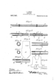
ing member, and Fi VIIIis a longitudinal I and t the latter being terminally rabbeted, as at 8,. Dis-' posed lon 'tudinally within this organize-- Y tubular member 7 of: the sheath, a which atter '.,(11). The other end "(12) of'the pusher blank utilized In said drawings :'Figure I is an elevation-of a pen holder embod ing my invention, and Fig. II is a longitudinalsection thereof Fig. III is a front end elevationof the pen. Fig. IV is a view of the blank of' one terminal of the pusher rod. Fig. V is a top plan view of the .pen releasing de-,
vice and a portion of the pusher rod, and Fig. VI is a bottom plan view thereof.- Fig.
VII is a transverse sectional View of the pusher" rod. terminal and the pen releassection thereof, and ig. IX is a viewof the in forming the releasing mem ber.
- I preferably employ a sheath'or case'com-q prising metallic end sections (5) and 6) e intermediate wooden. section and secured to the former sections.
tion is a pusher rod (9), havin the en-- larged extremital portion (10), so dered or otherwise secured thereto, and a coil spring (11) interposed between the base of said portion and the rabbeted terminal of the point 1,. preferably, employ a washer rod is originally in the form of a blank,
the occasion so -rei the drawings.-
as disclosed by Fig. IV of the accompany,
ing drawings, and provided with an a erture (13) medially thereof, the same, be oreits incorporation within the" sheath, being Patented Oct..2 6, 1909.
flexed to assume a cylindrical contour. Furthermore, the proxlmal end of the pusher rod is longitudinally slot-ted, as at 14, the said slot being designed for engagement with the depending, integrally formed er. tion (15) of the section (5), constitutin a portion of the sheath. The-function. of t is and its appurtenances. 'The en re easing da'ice (16) also comprises a. hunk, as exhibited in Fig. IX" ofth'edrawing's, the same being equipped with the "oppositely disposedlateral projections (17) and the centrally arranged extension (18' the gagement with the termmal when the releasing member has been bent in the-form shown in Fi In operatidriythe pen is securely held between the section 5)"ahd the releasingten. 1ni'nal-'(l6)', and whenit is desired to" remove the pen it is only necessalzygtoexerta' slight pressure on'the enlar e (10) or the terminal pusher rod wh1ch operation {slot andprojection (15) is obyiously to in sure a perfect guidance ,of the plun r rod and VI of causes the releasing member (16)." to' move and eflI'ectiVe and there is little if any, daii-I- ranged. g
It will-be seen fromthe foregoing [that the plunger rod 9 and pen ejector 16 being formed of sheet metal rolled intovtubular forms greatly cheapens their cost, owinito the fact that'they can be readily-blah ed ager of its component parts becoming deout by a punching and shaping machine. I
It will also be understood that the slot in 'the rod 9 provides a sim le and highly oiiicient means whereby the ongitudinal inove- 75 former projections being designed or.",enortion of the l pusher rod ..(9), and the a-tter for .en- 'gagement with the ,aperture (13) thereof,
'- ment of said rod may be guided by the inwardl projectin' and rther, sai
tions 17 of the pen ejector to have an interloekin engagement with said rod 9 at its slotte side, which terlocking engagements between vthe extensions 18 and aperture 13,-provides a strong connection between said rod and ejector on op osite sides thereof.-
at I claim is-:..-:-
' 1. In a pen holder, the
. .the body, of a tubu1ar:plunger rod therein surroun'din one end provided with a slot on one side and an opening on its other side, and a pen ejector of saidv rod and having an interloc ing engagement with the slot the combination with of a'tubular lunger' rod therein the v with a longitudinally arranged provided side slot and an opposite1ydisposed openlug 15 of the sheath 5, slot permits the projec-' supplemented by the in-.
combination with ing, and a pen ejector suirounding one end of said r0 and" provided with oppositely dis osed extensions 'for engagement with sai slot, and an end extension for engagei of sheet metal --r0lle ment with said 0 ening.-.
' 3. In a pen hol de1',-.th'e combination with the body, of a plun er rod therein formed d into tubular form and provided with a' longitudinal side slot and I an oppositel die osedopening and having one end e arg and a formed. ofjsheet metal rol ed into en ejector also tubular form and provided with extensions, said ejector surrounding the enlarged -end" of --said' rod and havingits extensions engaging with the slot and opening formed thlllh;
In testimony whereof I hereunto afiix my signature prese so of two witnesses.
. JOSEPH ALTMAN.
Witnesses:
' AmroN Amman,
Nmonnmnrnn.
Priority Applications (1)
| Application Number | Priority Date | Filing Date | Title |
|---|---|---|---|
| US45576908A US937747A (en) | 1908-10-01 | 1908-10-01 | Penholder. |
Applications Claiming Priority (1)
| Application Number | Priority Date | Filing Date | Title |
|---|---|---|---|
| US45576908A US937747A (en) | 1908-10-01 | 1908-10-01 | Penholder. |
Publications (1)
| Publication Number | Publication Date |
|---|---|
| US937747A true US937747A (en) | 1909-10-26 |
Family
ID=3006167
Family Applications (1)
| Application Number | Title | Priority Date | Filing Date |
|---|---|---|---|
| US45576908A Expired - Lifetime US937747A (en) | 1908-10-01 | 1908-10-01 | Penholder. |
Country Status (1)
| Country | Link |
|---|---|
| US (1) | US937747A (en) |
-
1908
- 1908-10-01 US US45576908A patent/US937747A/en not_active Expired - Lifetime
Similar Documents
| Publication | Publication Date | Title |
|---|---|---|
| US809419A (en) | Dispensing device. | |
| US2033256A (en) | Top for containers | |
| DE2044320A1 (en) | Thermostat with riveted Kontaktver connections and process for its manufacture | |
| US1045071A (en) | Toilet-powder dispenser. | |
| US706679A (en) | Cigar-perforator. | |
| US1119033A (en) | Grease-gun. | |
| US1454922A (en) | of chicago | |
| US1932796A (en) | Grease ram | |
| US370735A (en) | Paul e | |
| US1848608A (en) | oe chicago | |
| US1173865A (en) | Fountain-pen. | |
| US1911284A (en) | Closure for collapsible tubes | |
| US1901413A (en) | Valve construction for containers | |
| DE69102950T2 (en) | Valve for aerosol containers and aerosol container provided with such a valve. | |
| US1257905A (en) | Cigarette-holder. | |
| US918875A (en) | Powder-keg. | |
| DE621368C (en) | Spring contact with contact carbon, in which the carbon is held in place on the spring tongue by overlapping stapling members | |
| DE905753C (en) | Gas pressure switch | |
| AT49338B (en) | Lighter. | |
| US1159022A (en) | Pin-protector. | |
| US1142794A (en) | Lead-pencil. | |
| DE838072C (en) | Cigarette holder with ejector | |
| DE587791C (en) | Pressurized gas nozzle switch | |
| US1155859A (en) | Shaving-brush. | |
| US1913662A (en) | Pencil |