US9371782B2 - Control apparatus for internal combustion engine - Google Patents
Control apparatus for internal combustion engine Download PDFInfo
- Publication number
- US9371782B2 US9371782B2 US13/483,335 US201213483335A US9371782B2 US 9371782 B2 US9371782 B2 US 9371782B2 US 201213483335 A US201213483335 A US 201213483335A US 9371782 B2 US9371782 B2 US 9371782B2
- Authority
- US
- United States
- Prior art keywords
- valve
- working angle
- air amount
- intake
- intake air
- Prior art date
- Legal status (The legal status is an assumption and is not a legal conclusion. Google has not performed a legal analysis and makes no representation as to the accuracy of the status listed.)
- Expired - Fee Related, expires
Links
Images


Classifications
-
- F—MECHANICAL ENGINEERING; LIGHTING; HEATING; WEAPONS; BLASTING
- F02—COMBUSTION ENGINES; HOT-GAS OR COMBUSTION-PRODUCT ENGINE PLANTS
- F02D—CONTROLLING COMBUSTION ENGINES
- F02D13/00—Controlling the engine output power by varying inlet or exhaust valve operating characteristics, e.g. timing
- F02D13/02—Controlling the engine output power by varying inlet or exhaust valve operating characteristics, e.g. timing during engine operation
- F02D13/0223—Variable control of the intake valves only
- F02D13/0234—Variable control of the intake valves only changing the valve timing only
- F02D13/0238—Variable control of the intake valves only changing the valve timing only by shifting the phase, i.e. the opening periods of the valves are constant
-
- F—MECHANICAL ENGINEERING; LIGHTING; HEATING; WEAPONS; BLASTING
- F02—COMBUSTION ENGINES; HOT-GAS OR COMBUSTION-PRODUCT ENGINE PLANTS
- F02D—CONTROLLING COMBUSTION ENGINES
- F02D41/00—Electrical control of supply of combustible mixture or its constituents
- F02D41/02—Circuit arrangements for generating control signals
- F02D41/04—Introducing corrections for particular operating conditions
-
- F—MECHANICAL ENGINEERING; LIGHTING; HEATING; WEAPONS; BLASTING
- F02—COMBUSTION ENGINES; HOT-GAS OR COMBUSTION-PRODUCT ENGINE PLANTS
- F02D—CONTROLLING COMBUSTION ENGINES
- F02D9/00—Controlling engines by throttling air or fuel-and-air induction conduits or exhaust conduits
- F02D9/02—Controlling engines by throttling air or fuel-and-air induction conduits or exhaust conduits concerning induction conduits
-
- Y—GENERAL TAGGING OF NEW TECHNOLOGICAL DEVELOPMENTS; GENERAL TAGGING OF CROSS-SECTIONAL TECHNOLOGIES SPANNING OVER SEVERAL SECTIONS OF THE IPC; TECHNICAL SUBJECTS COVERED BY FORMER USPC CROSS-REFERENCE ART COLLECTIONS [XRACs] AND DIGESTS
- Y02—TECHNOLOGIES OR APPLICATIONS FOR MITIGATION OR ADAPTATION AGAINST CLIMATE CHANGE
- Y02T—CLIMATE CHANGE MITIGATION TECHNOLOGIES RELATED TO TRANSPORTATION
- Y02T10/00—Road transport of goods or passengers
- Y02T10/10—Internal combustion engine [ICE] based vehicles
- Y02T10/12—Improving ICE efficiencies
-
- Y02T10/18—
Definitions
- the invention relates to a control apparatus for an internal combustion engine that is equipped with a variable working angle mechanism that changes the working angle of an intake valve.
- variable valve characteristic mechanism that changes the valve characteristic of an intake valve.
- the variable valve characteristic mechanism include a variable working angle mechanism that changes the working angle of an intake valve, a variable valve timing mechanism that changes the valve timing of an intake valve, and the like.
- JP-05-001604 A Japanese Patent Application Publication No. 05-001604
- JP-05-001604 A Japanese Patent Application Publication No. 05-001604 A
- a mechanism that is equipped with two cams, namely, a large cam with a large working angle and a small cam with a small working angle, and changes over the cam for driving an intake valve between the large cam and the small cam to change the working angle of the intake valve.
- the working angle is usually changed in accordance with the change in an engine operation state such as an engine rotational speed or an engine load. However, under certain circumstances, the working angle is changed independently of the change in the engine operation state.
- variable valve characteristic mechanisms namely, a hydraulic variable valve timing mechanism that changes the valve timing of an intake valve through an oil pressure, and a variable working angle mechanism that changes the working angle of an intake valve through an oil pressure
- the timing for closing the intake valve becomes later than an intake bottom dead center.
- the air in the cylinder is pushed back into an intake port as the piston ascends.
- the working angle increases by a certain degree at this time, the amount of the air with which the cylinder is filled (a cylinder filling air amount) may become smaller than before the working angle increases.
- the working angle must be swiftly increased at this time to avoid misfire.
- the cylinder filling air amount namely, the engine load may be abruptly reduced to cause an abrupt fall in the engine rotational speed.
- the engine load may increase to cause the engine rotational speed to rev up abruptly.
- the working angle is increased within such a range that the valve-closing timing of the intake valve is earlier than the intake bottom dead center, the engine load increases due to the increase in the working angle, and the engine rotational speed revs up.
- the invention has been made in consideration of the foregoing circumstances, and attempts to solve a problem of providing a control apparatus for an internal combustion engine that can restrain the engine rotational speed from abruptly changing as a result of a change in the working angle of an intake valve.
- a control apparatus for an internal combustion engine comprise a variable working angle mechanism that changes a working angle of an intake valve, and a controller that, when the working angle is changed, corrects an opening degree of a valve for adjusting an intake air amount to change an amount of air to be filled in the cylinder (a cylinder filling air amount) in a direction reverse to a change of the intake air amount resulting from the change in the working angle.
- the opening degree of the valve for adjusting the intake air amount such as a throttle valve or an idle speed control (ISC) valve is corrected toward so as to change the cylinder filling air amount in the direction reverse to the change in the intake air amount.
- the opening degree of the valve for adjusting the intake air amount is corrected to increase the cylinder filling air amount, namely, toward such a side that the intake air amount increases.
- a control apparatus for an internal combustion engine comprises a variable working angle mechanism that changes a working angle of an intake valve, and a controller that, when the working angle is increased, corrects an opening degree of a valve for adjusting an intake air amount so as to increase the intake air amount.
- the cylinder filling air amount may decrease in accordance with the increase in the working angle, and cause a fall in the engine rotational speed.
- the opening degree of the valve for adjusting the intake air amount is corrected toward such a side that the intake air amount increases.
- the engine load can be restrained from decreasing as a result of the increase in the working angle, and the engine rotational speed can be restrained from abruptly changing as a result of the change in the working angle.
- a decrease in the intake air amount resulting from the increase in the working angle occurs when the valve-closing timing of the intake valve after the increase in the working angle is later than the intake bottom dead center.
- the opening degree of the valve for adjusting the intake air amount may be corrected to restrain the engine rotational speed from falling as a result of the increase in the working angle, when the valve-closing timing of the intake valve after the increase in the working angle is later than the intake bottom dead center.
- the amount or timing of the change in the intake air amount resulting from the change in the working angle changes depending on the valve timing of the intake valve.
- the amount and timing of the correction of the opening degree of the valve for adjusting the intake air amount which is made to restrain the intake air amount from changing as a result of the change in the working angle, may be changed in accordance with the valve timing of the intake valve at the time of the change in the working angle.
- the working angle when the working fluid pressure of the hydraulic variable valve timing mechanism becomes deficient, the working angle may be increased. Besides, when the working angle is increased by a certain degree at this time, the intake air amount may decrease to cause a fall in the engine rotational speed. Accordingly, in such an internal combustion engine, the opening degree of the aforementioned valve may be corrected when the working angle is increased in accordance with the deficiency in the working fluid pressure of the hydraulic variable valve timing mechanism.
- the amount of correction of the opening degree of the valve for adjusting the intake air amount is gradually reduced with the passage of time after an abrupt change in the engine rotational speed resulting from the change in the working angle is averted through the correction of the opening degree of the valve.
- FIG. 1 is a schematic view schematically showing an overall configuration of a control apparatus for an internal combustion engine according to the first embodiment of the invention
- FIG. 2 is a flowchart showing a processing procedure of an air correction routine adopted in the first embodiment of the invention
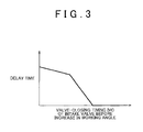
- FIG. 3 is a graph showing a relationship between a valve-closing timing of an intake valve and a delay time of the intake valve before an increase in a working angle in an example of a calculation map for calculating the delay time;
- FIG. 4 is a graph showing a relationship between the valve-closing timing of the intake valve and an air correction amount of the intake valve before an increase in a working angle in an example of a calculation map for calculating the air correction amount;
- FIG. 5 is a time chart showing a control mode at a time when the valve-closing timing of the intake valve before the increase in the working angle is later than an intake bottom dead center;
- FIG. 6 is a time chart showing a control mode at a time when the valve-closing timing of the intake valve before the increase in the working angle is earlier than the intake bottom dead center;
- FIG. 7 is a flowchart showing a processing procedure of an air correction routine adopted in the second embodiment of the invention.
- FIGS. 8A, 8B, and 8C are a view showing timings for opening and closing the intake valve and an exhaust valve, in particular, FIG. 8A shows timings before retardation of a valve timing, FIG. 8B shows timings after retardation of the valve timing, and FIG. 8C shows timings after an increase in the working angle respectively.
- the control apparatus for the internal combustion engine is mainly constituted by an electronic control unit 1 .
- the electronic control unit 1 is equipped with a central processing unit (a CPU) that performs various kinds of calculation processing related to engine control, a read-only memory (a ROM) in which programs and data for engine control are stored, and a random access memory (a RAM) that temporarily stores a calculation result of the CPU, detection results of sensors and the like.
- a CPU central processing unit
- a ROM read-only memory
- RAM random access memory
- Detection signals of, for example, various sensors (A) to (E) mentioned below, which are provided in respective regions of a vehicle, are input to the electronic control unit 1 .
- the sensor (A) is an airflow meter 2 that detects an intake air amount.
- the sensor (B) is an accelerator position sensor 3 that detects an accelerator operation position.
- the sensor (C) is a throttle sensor 4 that detects a throttle opening degree.
- the sensor (D) is a cam angle sensor 5 that outputs a signal (a cam angle signal) corresponding to a rotational angle (a cam angle) of a cam shaft.
- the sensor (E) is a crank angle sensor 6 that outputs a signal (a crank angle signal) corresponding to a rotational angle (a crank angle) of a crankshaft.
- various actuators (F) to (H) mentioned below which change the operation state of the internal combustion engine, are connected to the electronic control unit 1 .
- the electronic control unit 1 drives and controls the actuators to perform engine control, such as adjustment of the intake air amount and change of the valve timing and working angle of the intake valve.
- the actuator (F) is a throttle motor 8 that changes the opening degree of a throttle valve 7 as a valve for adjusting the intake air amount, namely, a throttle opening degree.
- the actuator (G) is an oil control valve (an OCV) 10 that changes the working fluid pressure of a variable valve timing mechanism (a VVT mechanism) 9 that changes the valve timing of the intake valve.
- the actuator (H) is an actuator 12 that drives a variable working angle mechanism 11 that changes the working angle of the intake valve.
- the electronic control unit 1 monitors whether or not the working fluid pressure of the VVT mechanism 9 is deficient. This deficiency in the working fluid pressure can be confirmed from, for example, a decrease in the response speed of the VVT mechanism 9 .
- valve timing of the intake valve changes toward a retardation side.
- the valve-opening timing of the intake valve becomes much later than an intake top dead center due to the retardation of the valve timing.
- the electronic control unit 1 increases the working angle of the intake valve to advance the valve-opening timing of the intake valve, thereby restraining the pressure loss of the intake valve from increasing and hence avoiding misfire. It should be noted that the working angle of the intake valve is rapidly increased at this time to avoid misfire.
- the valve-closing timing of the intake valve becomes much later than an intake bottom dead center.
- the amount of air to be filled in the cylinder (the cylinder filling air amount) may become smaller than before the working angle is increased.
- the working angle must be swiftly revved up at this time to avoid misfire.
- the cylinder filling air amount may be abruptly reduced, and thereby causing an abrupt fall in the engine rotational speed.
- the electronic control unit 1 in order to prevent the engine rotational speed from abruptly falling as a result of such an increase in the working angle, the electronic control unit 1 performs the following control. This control is performed through a processing of an air correction routine shown in FIG. 2 . The processing of this routine is performed by the electronic control unit 1 every time a command to change the working angle of the intake valve is issued.
- step S 100 it is confirmed first in step S 100 whether or not the working angle of the intake valve has been increased from a minimum working angle as a minimum value in a variable working angle range to a maximum working angle as a maximum value in the variable working angle range.
- the working angle has not been thus increased in this case (S 100 : NO)
- the current processing of this routine is immediately terminated.
- step S 101 when the working angle is increased as described above (S 100 : YES), it is confirmed in the following step S 101 whether or not the internal combustion engine is currently in idle operation. It should be noted herein that when the internal combustion engine is not in idle operation, the current processing of this routine is immediately terminated. Otherwise, the processing is shifted to step S 102 .
- the working angle of the intake valve is increased from the minimum working angle to the maximum working angle during idle operation, for example, when the deficiency in the working fluid pressure of the VVT mechanism 9 .
- a delay time is calculated on the basis of a valve timing of the intake valve at that time in step S 102 .
- the delay time as mentioned herein is calculated from a valve-closing timing IVC of the intake valve before the increase in the working angle, on the basis of a calculation map shown in FIG. 3 .
- the valve-closing timing IVC indicates the magnitude of a crank angle from the intake bottom dead center to the closing of the intake valve.
- the value of the delay time is set to “0”.
- the value of the delay time is set to a value that increases as the valve-closing timing IVC is advanced.
- an air correction amount is calculated on the basis of a valve timing of the intake valve at that time.
- the air correction amount as mentioned herein is calculated from the valve-closing timing IVC of the intake valve before the increase in the working angle, on the basis of a calculation map shown in FIG. 4 .
- an air correction amount qvtf is set to a value that increases as the valve-closing timing of the intake valve before the increase in the working angle is retarded.
- the value of the air correction amount qvtf is set to “0”.
- the delay time and the air correction amount qvtf are thus calculated, the lapse of the aforementioned calculated delay time from the issuance of a command to increase the working angle is awaited in the following step S 104 , and then, a required intake air amount qcal is corrected toward an increase side in accordance with the aforementioned calculated air correction amount qvtf in step S 105 .
- the required intake air amount qcal is used to calculate a throttle opening degree. The throttle opening degree is increased as the value of the required intake air amount qcal increases.
- the throttle opening degree is corrected toward such a side that the cylinder filling air amount changes in a direction reverse to a change of the cylinder filling air amount resulting from the change in the working angle, namely, toward such a side that the intake air amount increases.
- step S 106 a gradual reduction processing is performed to gradually reduce the value of the air correction amount qvtf with the passage of time until the air correction amount qvtf becomes equal to “0”. Then, when the air correction amount qvtf is gradually reduced to “0”, the current processing of this routine is terminated.
- FIGS. 5 and 6 a control mode in the case where the processing of the aforementioned air correction routine is performed is indicated by a solid line, and that a control mode in the case where the processing of the aforementioned air correction routine is not performed is indicated by a broken line.
- FIG. 5 shows a control mode at the time when the valve-closing timing IVC of the intake valve before the increase in the working angle is later than the intake bottom dead center.
- the required intake air amount qcal is held unchanged even when the working angle evcam of the intake valve is increased in this case. In this case, therefore, the throttle opening degree is not changed either.
- the working angle evcam is increased, the cylinder filling air amount, namely, an engine load klsm decreases to cause a fall in an engine rotational speed ene.
- the required intake air amount qcal is corrected toward the increase side, and hence the throttle opening degree is corrected toward the increase side, in accordance with the increase in the working angle evcam of the intake valve in this case.
- the delay time in this case is set to “0”, and that the correction of the required intake air amount qcal, namely, the correction of the throttle opening degree at this time is started simultaneously with the increase in the working angle evcam.
- FIG. 6 shows a control mode at the time when the valve-closing timing IVC of the intake valve before the increase in the working angle is earlier than the intake bottom dead center.
- the working angle evcam of the intake valve is increased to avoid the occurrence of misfire due to an increase in the pressure loss resulting from the subsequent shift of the valve timing evt of the intake valve toward the retardation side.
- the engine load klsm temporarily increases. Then, in the case where the processing of the air correction routine is not performed, the engine load klsm decreases in accordance with the increase in the working angle evcam after the valve-closing timing IVC of the intake valve reaches the intake bottom dead center, and causes a fall in the engine rotational speed ene.
- the delay time is set to a time that lengthens as the valve-closing timing IVC of the intake valve before the increase in the working angle is advanced, so that the throttle opening degree is corrected at the timing when the intake air amount decreases as a result of the increase in the working angle evcam.
- the control apparatus for the internal combustion engine can achieve the following effects.
- the throttle opening degree is corrected so as to as change the cylinder filling air amount, namely, toward such a side that the cylinder filling air amount changes, in the direction reverse to a change resulting from the change in the working angle.
- the opening degree of the valve for adjusting the intake air amount is corrected toward such a side that the cylinder filling air amount increases.
- intake air correction is made when the valve-closing timing of the intake valve after the increase in the working angle is later than the intake bottom dead center.
- the air correction amount qvtf and the delay time are changed in accordance with the valve timing of the intake valve. That is, in this embodiment of the invention, the amount and timing of correction of the throttle opening degree corresponding to the increase in the working angle are changed in accordance with the valve timing of the intake valve at the time of the change in the working angle.
- the throttle opening degree can be adequately corrected to restrain the intake air amount from decreasing as a result of the increase in the working angle.
- the throttle opening degree is corrected when the working angle is increased in accordance with the deficiency in the working fluid pressure of the VVT mechanism 9 in which the working angle is increased at high speed.
- the engine rotational speed can be adequately restrained from abruptly falling due to an abrupt decrease in the intake air amount under such circumstances.
- control logic of the air correction routine has versatility so as to be applicable to different types of internal combustion engines as well.
- an air correction routine adopted in this embodiment of the invention as described above is obtained by altering the processes of step S 102 and step S 103 in the routine according to the first embodiment of the invention shown in FIG. 2 , namely, the processes related to the calculation of the delay time and the air correction amount qvtf.
- a delay time is calculated in step S 102 ′ on the basis of a valve timing of the intake valve, a speed of change in the working angle, and a volume (an intake manifold volume) of an intake manifold of an internal combustion engine. More specifically, the delay time is set to a time that lengthens as the speed of change in the working angle decreases or as the volume of the intake manifold of the internal combustion engine increases.
- the air correction amount qvtf is calculated in step S 103 ′ from the valve timing of the intake valve at that time and the displacement of an internal combustion engine. More specifically, the air correction amount qvtf is set to a value that increases as the displacement of the internal combustion engine increases.
- This embodiment of the invention as described above can achieve the following effects in addition to the aforementioned effects (1) to (5).
- (6) The time from the increase in the working angle to the occurrence of a decrease in the intake air amount resulting therefrom lengthens as the volume of the intake manifold of the internal combustion engine increases.
- the delay time can be adequately set such that the intake air amount can be restrained from abruptly changing as a result of the change in the working angle even in an internal combustion engine having an intake manifold with a different volume.
- the delay time can be adequately set such that the intake air amount can be restrained from abruptly changing as a result of the change in the working angle even in the case where the speed of change in the working angle is different.
- the air correction amount qvtf can be adequately set such that the intake air amount can be restrained from abruptly changing as a result of the change in the working angle even in an internal combustion engine with a different displacement.
- each of the foregoing embodiments of the invention can also be implemented after being modified as follows.
- the air correction amount qvtf is gradually reduced with the passage of time.
- the air correction amount qvtf may be held unchanged until the working angle returns to its original value or the engine operation state changes.
- the correction of the throttle opening degree (hereinafter referred to as the air correction of the throttle opening degree) is made to restrain the engine rotational speed from abruptly changing as a result of the increase in the working angle.
- the air correction of the throttle opening degree may be made. It should be noted that an abrupt fall in the engine rotational speed corresponding to the increase in the working angle occurs only when the speed of change in the working angle is high. Thus, even if the air correction of the throttle opening degree is made only when the speed of change in the working angle is higher than a prescribed speed, the engine rotational speed can be restrained from abruptly falling in accordance with the increase in the working angle.
- the air correction of the throttle opening degree is made toward such a side that the intake air amount increases at the time of the increase in the working angle.
- the working angle is increased within such a range that the valve-closing timing of the intake valve precedes the intake bottom dead center
- the cylinder filling air amount increases due to the increase in the working angle, and causes the engine rotational speed to rev up.
- the air correction of the throttle opening degree is made when the valve-closing timing of the intake valve after the increase in the working angle is earlier than the intake bottom dead center
- the air correction of the throttle opening degree is made toward such a side that the intake air amount increases in accordance with the increase in the working angle.
- the engine rotational speed can be restrained from abruptly changing in accordance with the increase in the working angle.
- the air correction of the throttle opening degree is made when the working angle is increased.
- the intake air amount may abruptly change in accordance with a reduction in the working angle as well, and thereby causing an abrupt change in the engine rotational speed. Therefore, in the case where an abrupt change in the engine rotational speed corresponding to such a reduction in the working angle causes a problem, the air correction of the throttle opening degree may be made at the time of the reduction in the working angle.
- the air correction amount and the delay timing are changed in accordance with the valve timing of the intake valve.
- the valve timing of the intake valve at the time of an change in the working angle, which causes an abrupt change in the engine rotational speed is fixed or the internal combustion engine is not equipped with a variable valve timing mechanism
- the change in the air correction amount or the delay timing corresponding to the valve timing may be omitted.
- the air correction is made for the opening degree of the throttle valve 7 .
- a similar air correction is made for the opening degree of a valve other than the throttle valve that adjusts the intake air amount, such as an ISC valve or the like, the engine rotational speed can be restrained from abruptly changing in accordance with the change in the working angle of the intake valve.
- the invention is also applicable to an internal combustion engine that is not equipped with a VVT mechanism, as long as the internal combustion engine is equipped with a variable working angle mechanism.
Landscapes
- Engineering & Computer Science (AREA)
- Chemical & Material Sciences (AREA)
- Combustion & Propulsion (AREA)
- Mechanical Engineering (AREA)
- General Engineering & Computer Science (AREA)
- Output Control And Ontrol Of Special Type Engine (AREA)
- Electrical Control Of Air Or Fuel Supplied To Internal-Combustion Engine (AREA)
Abstract
Description
Claims (8)
Applications Claiming Priority (2)
| Application Number | Priority Date | Filing Date | Title |
|---|---|---|---|
| JP2011123555A JP2012251464A (en) | 2011-06-01 | 2011-06-01 | Control apparatus for internal combustion engine |
| JP2011-123555 | 2011-06-01 |
Publications (2)
| Publication Number | Publication Date |
|---|---|
| US20120310511A1 US20120310511A1 (en) | 2012-12-06 |
| US9371782B2 true US9371782B2 (en) | 2016-06-21 |
Family
ID=47173581
Family Applications (1)
| Application Number | Title | Priority Date | Filing Date |
|---|---|---|---|
| US13/483,335 Expired - Fee Related US9371782B2 (en) | 2011-06-01 | 2012-05-30 | Control apparatus for internal combustion engine |
Country Status (3)
| Country | Link |
|---|---|
| US (1) | US9371782B2 (en) |
| JP (1) | JP2012251464A (en) |
| DE (1) | DE102012209158A1 (en) |
Families Citing this family (3)
| Publication number | Priority date | Publication date | Assignee | Title |
|---|---|---|---|---|
| JP5384413B2 (en) * | 2010-03-31 | 2014-01-08 | 本田技研工業株式会社 | Internal combustion engine with valve deactivation mechanism |
| JP2012251464A (en) * | 2011-06-01 | 2012-12-20 | Toyota Motor Corp | Control apparatus for internal combustion engine |
| JP7115028B2 (en) * | 2018-05-22 | 2022-08-09 | マツダ株式会社 | Compression ignition engine controller |
Citations (10)
| Publication number | Priority date | Publication date | Assignee | Title |
|---|---|---|---|---|
| JPH051604A (en) | 1991-06-27 | 1993-01-08 | Nissan Motor Co Ltd | Control device of internal combustion engine |
| US20030106542A1 (en) * | 2001-12-06 | 2003-06-12 | Nissan Motor Co., Ltd. | Engine control system of internal combustion engine with variable compression ratio mechanism and exhaust-gas recirculation control system |
| US20040035391A1 (en) * | 2002-08-26 | 2004-02-26 | Toyota Jidosha Kabushiki Kaisha | Control system of internal combustion engine |
| US20050229880A1 (en) | 2004-04-15 | 2005-10-20 | Akira Hashizume | Valve actuation controlling apparatus and method for engine |
| US20060086338A1 (en) * | 2004-10-22 | 2006-04-27 | Toshikazu Kato | Idle speed controller for internal combustion engine |
| US20060162681A1 (en) * | 2005-01-25 | 2006-07-27 | Toyota Jidosha Kabushiki Kaisha | Intake air amount control apparatus for internal combustion engine |
| US20060225678A1 (en) * | 2005-04-08 | 2006-10-12 | Mitsubishi Jidosha Kogyo Kabushiki Kaisha | Intake control apparatus of internal combustion engine |
| US20070039579A1 (en) | 2005-08-19 | 2007-02-22 | Naohide Fuwa | Control apparatus and control method for internal combustion engine |
| US20120310511A1 (en) * | 2011-06-01 | 2012-12-06 | Toyota Jidosha Kabushiki Kaisha | Control apparatus for internal combustion engine |
| US20150039209A1 (en) * | 2013-07-30 | 2015-02-05 | Toyota Jidosha Kabushiki Kaisha | Diagnostic system and diagnostic method for internal combustion engine |
Family Cites Families (1)
| Publication number | Priority date | Publication date | Assignee | Title |
|---|---|---|---|---|
| JP4947891B2 (en) * | 2004-11-19 | 2012-06-06 | トヨタ自動車株式会社 | Control device for internal combustion engine |
-
2011
- 2011-06-01 JP JP2011123555A patent/JP2012251464A/en active Pending
-
2012
- 2012-05-30 US US13/483,335 patent/US9371782B2/en not_active Expired - Fee Related
- 2012-05-31 DE DE102012209158A patent/DE102012209158A1/en not_active Withdrawn
Patent Citations (12)
| Publication number | Priority date | Publication date | Assignee | Title |
|---|---|---|---|---|
| JPH051604A (en) | 1991-06-27 | 1993-01-08 | Nissan Motor Co Ltd | Control device of internal combustion engine |
| US20030106542A1 (en) * | 2001-12-06 | 2003-06-12 | Nissan Motor Co., Ltd. | Engine control system of internal combustion engine with variable compression ratio mechanism and exhaust-gas recirculation control system |
| US20040035391A1 (en) * | 2002-08-26 | 2004-02-26 | Toyota Jidosha Kabushiki Kaisha | Control system of internal combustion engine |
| US20050229880A1 (en) | 2004-04-15 | 2005-10-20 | Akira Hashizume | Valve actuation controlling apparatus and method for engine |
| JP2005299594A (en) | 2004-04-15 | 2005-10-27 | Toyota Motor Corp | Engine valve characteristic control device |
| US20060086338A1 (en) * | 2004-10-22 | 2006-04-27 | Toshikazu Kato | Idle speed controller for internal combustion engine |
| US20060162681A1 (en) * | 2005-01-25 | 2006-07-27 | Toyota Jidosha Kabushiki Kaisha | Intake air amount control apparatus for internal combustion engine |
| US20060225678A1 (en) * | 2005-04-08 | 2006-10-12 | Mitsubishi Jidosha Kogyo Kabushiki Kaisha | Intake control apparatus of internal combustion engine |
| US20070039579A1 (en) | 2005-08-19 | 2007-02-22 | Naohide Fuwa | Control apparatus and control method for internal combustion engine |
| JP2007051603A (en) | 2005-08-19 | 2007-03-01 | Toyota Motor Corp | Control device for internal combustion engine |
| US20120310511A1 (en) * | 2011-06-01 | 2012-12-06 | Toyota Jidosha Kabushiki Kaisha | Control apparatus for internal combustion engine |
| US20150039209A1 (en) * | 2013-07-30 | 2015-02-05 | Toyota Jidosha Kabushiki Kaisha | Diagnostic system and diagnostic method for internal combustion engine |
Also Published As
| Publication number | Publication date |
|---|---|
| JP2012251464A (en) | 2012-12-20 |
| DE102012209158A1 (en) | 2012-12-06 |
| US20120310511A1 (en) | 2012-12-06 |
Similar Documents
| Publication | Publication Date | Title |
|---|---|---|
| US8768601B2 (en) | Control device for internal combustion engine having variable valve mechanism | |
| US20150034052A1 (en) | Engine Control Device | |
| JP5024216B2 (en) | Ignition timing control device and ignition timing control method for internal combustion engine | |
| JP2013144946A (en) | Internal combustion engine control device | |
| US20100154740A1 (en) | Variable valve timing mechanism control apparatus and control method | |
| US9371782B2 (en) | Control apparatus for internal combustion engine | |
| JP6350304B2 (en) | Lean burn engine | |
| JP2003314308A (en) | Valve characteristic control device for internal combustion engine | |
| US7152578B2 (en) | Valve characteristic controlling apparatus and method for internal combustion engine | |
| US20090205599A1 (en) | Adaptive individual dynamic volumetric efficiency optimization for engines with variable cam phasers and variable lift | |
| JP5747583B2 (en) | Control device for variable compression ratio internal combustion engine | |
| JP6191230B2 (en) | Control device and control method for internal combustion engine | |
| JP5720503B2 (en) | Variable valve gear | |
| US8989987B2 (en) | Engine control device | |
| JP2009243372A (en) | Method and device for controlling internal combustion engine | |
| JP3454082B2 (en) | Fuel injection control device for internal combustion engine | |
| JP5397559B2 (en) | Control device for internal combustion engine | |
| JP2009046995A (en) | Control system for variable valve mechanism of internal combustion engine | |
| JP2005113772A (en) | Knock avoidance device | |
| JP4841382B2 (en) | Internal combustion engine | |
| JPH0814073A (en) | Engine control device with variable valve mechanism | |
| JP5316129B2 (en) | Intake air amount control device | |
| US8620562B2 (en) | Variable valve system control apparatus | |
| JP5041167B2 (en) | Engine control device | |
| JP2010229911A (en) | Control device for variable valve mechanism |
Legal Events
| Date | Code | Title | Description |
|---|---|---|---|
| AS | Assignment |
Owner name: TOYOTA JIDOSHA KABUSHIKI KAISHA, JAPAN Free format text: ASSIGNMENT OF ASSIGNORS INTEREST;ASSIGNORS:WAKAYA, IPPEI;MIYANOO, YUJI;SHOGENJI, YOSHIYUKI;AND OTHERS;REEL/FRAME:028287/0058 Effective date: 20120521 |
|
| ZAAA | Notice of allowance and fees due |
Free format text: ORIGINAL CODE: NOA |
|
| ZAAB | Notice of allowance mailed |
Free format text: ORIGINAL CODE: MN/=. |
|
| STCF | Information on status: patent grant |
Free format text: PATENTED CASE |
|
| MAFP | Maintenance fee payment |
Free format text: PAYMENT OF MAINTENANCE FEE, 4TH YEAR, LARGE ENTITY (ORIGINAL EVENT CODE: M1551); ENTITY STATUS OF PATENT OWNER: LARGE ENTITY Year of fee payment: 4 |
|
| FEPP | Fee payment procedure |
Free format text: MAINTENANCE FEE REMINDER MAILED (ORIGINAL EVENT CODE: REM.); ENTITY STATUS OF PATENT OWNER: LARGE ENTITY |
|
| LAPS | Lapse for failure to pay maintenance fees |
Free format text: PATENT EXPIRED FOR FAILURE TO PAY MAINTENANCE FEES (ORIGINAL EVENT CODE: EXP.); ENTITY STATUS OF PATENT OWNER: LARGE ENTITY |
|
| STCH | Information on status: patent discontinuation |
Free format text: PATENT EXPIRED DUE TO NONPAYMENT OF MAINTENANCE FEES UNDER 37 CFR 1.362 |
|
| FP | Lapsed due to failure to pay maintenance fee |
Effective date: 20240621 |