US9369159B2 - Method and device for processing signals based on transmission mixer, frequency multiplier, and subharmonic mixing - Google Patents
Method and device for processing signals based on transmission mixer, frequency multiplier, and subharmonic mixing Download PDFInfo
- Publication number
- US9369159B2 US9369159B2 US13/825,960 US201113825960A US9369159B2 US 9369159 B2 US9369159 B2 US 9369159B2 US 201113825960 A US201113825960 A US 201113825960A US 9369159 B2 US9369159 B2 US 9369159B2
- Authority
- US
- United States
- Prior art keywords
- component
- frequency
- signal
- subharmonically
- mixed signal
- Prior art date
- Legal status (The legal status is an assumption and is not a legal conclusion. Google has not performed a legal analysis and makes no representation as to the accuracy of the status listed.)
- Active, expires
Links
- 230000005540 biological transmission Effects 0.000 title claims description 13
- 238000000034 method Methods 0.000 title claims description 13
- 238000012545 processing Methods 0.000 title claims description 9
- 238000005516 engineering process Methods 0.000 claims description 6
- 239000010409 thin film Substances 0.000 claims description 3
- 239000010408 film Substances 0.000 claims description 2
- 238000011161 development Methods 0.000 description 7
- 230000008901 benefit Effects 0.000 description 4
- 238000004891 communication Methods 0.000 description 4
- 238000013459 approach Methods 0.000 description 3
- 238000006243 chemical reaction Methods 0.000 description 3
- 238000010586 diagram Methods 0.000 description 3
- 230000000694 effects Effects 0.000 description 3
- 238000010276 construction Methods 0.000 description 2
- 230000001747 exhibiting effect Effects 0.000 description 2
- 230000003321 amplification Effects 0.000 description 1
- 230000002238 attenuated effect Effects 0.000 description 1
- 238000013461 design Methods 0.000 description 1
- 238000004519 manufacturing process Methods 0.000 description 1
- 238000012986 modification Methods 0.000 description 1
- 230000004048 modification Effects 0.000 description 1
- 238000003199 nucleic acid amplification method Methods 0.000 description 1
- 230000005855 radiation Effects 0.000 description 1
Images


Classifications
-
- H—ELECTRICITY
- H04—ELECTRIC COMMUNICATION TECHNIQUE
- H04B—TRANSMISSION
- H04B1/00—Details of transmission systems, not covered by a single one of groups H04B3/00 - H04B13/00; Details of transmission systems not characterised by the medium used for transmission
- H04B1/02—Transmitters
- H04B1/04—Circuits
-
- G—PHYSICS
- G01—MEASURING; TESTING
- G01S—RADIO DIRECTION-FINDING; RADIO NAVIGATION; DETERMINING DISTANCE OR VELOCITY BY USE OF RADIO WAVES; LOCATING OR PRESENCE-DETECTING BY USE OF THE REFLECTION OR RERADIATION OF RADIO WAVES; ANALOGOUS ARRANGEMENTS USING OTHER WAVES
- G01S13/00—Systems using the reflection or reradiation of radio waves, e.g. radar systems; Analogous systems using reflection or reradiation of waves whose nature or wavelength is irrelevant or unspecified
- G01S13/02—Systems using reflection of radio waves, e.g. primary radar systems; Analogous systems
- G01S13/50—Systems of measurement based on relative movement of target
- G01S13/58—Velocity or trajectory determination systems; Sense-of-movement determination systems
- G01S13/583—Velocity or trajectory determination systems; Sense-of-movement determination systems using transmission of continuous unmodulated waves, amplitude-, frequency-, or phase-modulated waves and based upon the Doppler effect resulting from movement of targets
-
- G—PHYSICS
- G01—MEASURING; TESTING
- G01S—RADIO DIRECTION-FINDING; RADIO NAVIGATION; DETERMINING DISTANCE OR VELOCITY BY USE OF RADIO WAVES; LOCATING OR PRESENCE-DETECTING BY USE OF THE REFLECTION OR RERADIATION OF RADIO WAVES; ANALOGOUS ARRANGEMENTS USING OTHER WAVES
- G01S7/00—Details of systems according to groups G01S13/00, G01S15/00, G01S17/00
- G01S7/02—Details of systems according to groups G01S13/00, G01S15/00, G01S17/00 of systems according to group G01S13/00
- G01S7/03—Details of HF subsystems specially adapted therefor, e.g. common to transmitter and receiver
-
- H—ELECTRICITY
- H03—ELECTRONIC CIRCUITRY
- H03B—GENERATION OF OSCILLATIONS, DIRECTLY OR BY FREQUENCY-CHANGING, BY CIRCUITS EMPLOYING ACTIVE ELEMENTS WHICH OPERATE IN A NON-SWITCHING MANNER; GENERATION OF NOISE BY SUCH CIRCUITS
- H03B19/00—Generation of oscillations by non-regenerative frequency multiplication or division of a signal from a separate source
- H03B19/16—Generation of oscillations by non-regenerative frequency multiplication or division of a signal from a separate source using uncontrolled rectifying devices, e.g. rectifying diodes or Schottky diodes
Definitions
- Described below are a method and device for processing signals.
- a system with separate transmitting and receiving sections generates and modulates the high-frequency signals by the transmitting section and amplifies, filters, mixes, and demodulates received signals with the aid of a separately implemented receiving section.
- Transmitting and receiving sections may be equipped with different antennae, or may use a common antenna by way of a transmitting/receiving coupler.
- Such a system is frequently excessively complex and requires a plurality of component elements to be put into effect. For example, component parts which are complex to assemble and which are typically connected in what is referred to as a chip & wire construction are required in order to generate and receive high frequencies.
- a further system uses a transmission mixer, which allows for the simultaneous transmission and reception of high-frequency signals.
- the transmission signal also serves as a local oscillator signal for the step-down conversion of the received signals.
- An aspect of the method is to avoid the disadvantage referred to heretofore and, in particular, to provide a solution which allows for a simple and economical system for generating and receiving high-frequency signals.
- the first and second components take on different functions, but may be combined separately or jointly in one physical unit.
- the first component among other things, to provide the functionality for the forwarding of the input signal, and for the second component to multiply the frequency of the forwarded signal in an efficient manner. Any attenuation losses of the first component can be compensated, for example, by the input signal exhibiting a sufficiently high signal strength.
- the approach allows, for example, for a tripling or five-fold increase in the frequency of the input signal.
- the provision of the input signal and (see hereinafter) processing of the received signal provided by the second component can therefore take place in an appreciably lower frequency range.
- the first component is a transmission mixer.
- the transmission mixer routes (transmits) the input signal to the second component and has, e.g., in the opposite direction, i.e. for signals which are provided by the second component, a step-down conversion or step-down mixing functionality.
- the second component provides a frequency-multiplying functionality in one direction.
- the second component provides a subharmonic mixing functionality. Accordingly, signals received by the second component can be transformed into a frequency range which lies perceptibly below the frequency of the signal emitted by the antenna. The (further) processing of the received signal is therefore made perceptibly easier.
- one development involves the received signal being subharmonically mixed by the second component and a signal with the frequency f 2 ⁇ 2 f i
- the signal received from the second component is step-down-mixed by the first component.
- a signal is provided by the first component with the frequency f 3 ⁇ f i wherein f i designates the frequency of the input signal or, respectively, the frequency of the signal provided to the second component, and f 3 designates the frequency of the signal which was mixed subharmonically by the second component and transmitted to the first component.
- the step-down-mixed signal is processed and, on the basis of the step-down-mixed signal, an item of information contained in the received signal can be detected.
- a device for processing signals includes a first component, which is connected to a second component, where the second component exhibits at least one component part with a non-linear characteristic curve, on the basis of which the frequency of a signal received from the component can be multiplied.
- the first component may be a transmission mixer.
- the device may be applied in conjunction with Doppler or radar sensors.
- the proposed solution may be used in order to determine information relating to objects arranged in a radiation emission direction, such as distance, speed etc.
- the component part with the non-linear characteristic curve includes two anti-parallel connected diodes.
- the diodes are tuning diodes or Schottky diodes.
- first component and/or the second component is designed in PCB technology, in thin-film technology, in thick-film technology, or as an integrated circuit.
- the second component includes at least one filter, in particular at least one high-pass filter and at least one low-pass filter.
- An additional embodiment is that the at least one non-linear component part of the second component is connected via the low-pass filter to the first component, and in that the at least one non-linear component part is connected via the high-pass filter directly or indirectly to an antenna.
- a communications system or a radar system comprising at least one of the devices described herein.
- FIG. 1 is a schematic block diagram providing a representation of a transmitting mixer
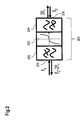
- FIG. 2 is a schematic block diagram for a structure of a second component comprising a filter, an anti-parallel connected diode pair with a cubic current/voltage characteristic curve, and a further filter;
- FIG. 3 is a schematic block diagram of an interconnection of the first component and the second component.
- a first component and a second component are connected to one another.
- the first component is a transmitting mixer.
- the transmitting mixer may be operated as a step-up or step-down transformer.
- the transmitting mixer may be used as a step-down transformer.
- FIG. 1 shows a transmitting mixer 101 with a connection 102 and a connection 103 .
- a signal with a frequency f LO this is, for example, a frequency which can also be used by a local oscillator
- f LO this is, for example, a frequency which can also be used by a local oscillator
- a reflected signal with a frequency f RF is received at the connection 103 .
- the transmitting mixer 101 provides a difference signal with the frequency f RF ⁇ f LO at an output 104 .
- the transmitting mixer 101 can be lossy, i.e. that the signal which leaves the transmitting mixer 101 at the connection 103 can be attenuated in relation to the signal which is applied to the connection 102 .
- the second component can on the one hand be operated as a frequency multiplier, e.g. as a frequency tripler, and, on the other, as a subharmonic mixer.
- the second component may, for example, exhibit an anti-parallel connected diode pair, exhibiting a cubic current/voltage characteristic curve.
- Such a characteristic curve can be efficiently used to produce a (sinusoidal) signal with a frequency 3 f from a sinusoidal signal with a frequency f.
- FIG. 2 shows a diagrammatic layout of such a second component 201 , comprising a filter 202 , an anti-parallel connected diode pair 203 with a cubic current/voltage characteristic curve, and a filter 204 .
- the filter 202 is connected via the anti-parallel-connected diodes 203 to the filter 204 .
- the second component 201 exhibits a connection 205 at the filter 202 , and a connection 206 at the filter 204 .
- the second component 201 is designed in such a way that it also takes effect as a (subharmonic) mixer. To do this, a signal with high capacity and a frequency f 1 is applied to the connection 205 , and a signal with a frequency f 2 ⁇ 3f i is applied to the connection 206 .
- the second component can be designed in the direction from the connection 206 to the connection 205 in such a way that a signal is provided at the connection 205 , which in particular exhibits the difference frequency from f 2 and twice the frequency f 1 .
- Filter 202 may include a low-pass filter and filter 204 as a high-pass filter.
- FIG. 3 shows an interconnection of the first component 101 and the second component 201 .
- Such a combination can be used, for example, in a Doppler radar.
- a signal with a frequency f LO is applied to the connection 102 of the transmitting mixer 101 , passes through the transmission mixer 101 with slight attenuation and arrives at the connection 205 of the second component 201 .
- the second component 201 triples the frequency of this signal and therefore provides a signal with the frequency 3 f LO at the connection 206 , the signal being emitted via an antenna 301 connected to the connection 206 .
- the signal thus emitted strikes an object 302 , wherein a part of the emitted signal is reflected with the frequency 3 f LO +f doppler , is detected by the antenna 301 , and is forwarded to the connection 206 of the second component 201 .
- This signal is subharmonically mixed in the second component 201 and converted into a signal with the frequency f LO +f doppler , which is forwarded to the transmission mixer 101 via the connection 205 .
- the transmitting mixer 101 provides a signal with the frequency f doppler at its output 104 , after a frequency conversion. On the basis of this frequency f doppler it is possible, for example, to determine the speed of the object 302 .
- the signal with the frequency f LO which is provided at the input 102 , may exhibit a sufficiently high output such that, despite attenuation by the first component 101 , the second component 201 can be operated at its working point.
- FMCW Frequency Modulated Continuous Wave
- the approach is suited to use with radar sensors at very high frequencies, since it is specifically at high frequencies that a generation and amplification of frequencies is very much more difficult to master than at low frequencies.
- the solution presented advantageously shifts the frequency generation to a third of the actual transmission frequency. Reception of the signals is simplified accordingly, since no amplifier is required in the reception path.
- the circuit can be used to particular advantage if the transmission frequency f of the radar is selected in such a way that the frequency f/3 can be generated with adequately high output and, respectively, in a cost-effective manner.
- the solution presented can also be used in communications systems, as well as to measure the distance interval between two systems of the same type.
- first and second components in particular the second component, can be designed or manufactured in PCB technology or alternative construction techniques, such as thin film, thick layer, or even as an integrated circuit.
- the filters of the second component can be configured in such a way that they function as adjustment element(s). Moreover, the filter can be configured in such a way that undesirable mixed products (frequencies) are suppressed. This could, for example, simplify a radio license for corresponding systems.
- the anti-parallel arrangement of two diodes for the provision of the cubic current/voltage characteristic curve is cited above.
- another non-linear component part may also be used instead of the diode(s).
- varistors or capacitance diodes may be used.
- Schottky diodes e.g. flip-chop Schottky diodes
- Combinations of the component parts referred to here are also possible.
- the second component may also be dimensioned, with suitable non-linear component parts, as a frequency five-fold amplifier.
- suitable non-linear component parts as a frequency five-fold amplifier.
- use is not made of the coefficient of the cubic term x 3 of the Taylor series of the non-linearity used, but instead of the coefficient of the term x 5 .
Landscapes
- Engineering & Computer Science (AREA)
- Radar, Positioning & Navigation (AREA)
- Remote Sensing (AREA)
- Computer Networks & Wireless Communication (AREA)
- Physics & Mathematics (AREA)
- General Physics & Mathematics (AREA)
- Signal Processing (AREA)
- Radar Systems Or Details Thereof (AREA)
Applications Claiming Priority (4)
| Application Number | Priority Date | Filing Date | Title |
|---|---|---|---|
| DE102010041372 | 2010-09-24 | ||
| DE102010041372.0 | 2010-09-24 | ||
| DE102010041372A DE102010041372A1 (de) | 2010-09-24 | 2010-09-24 | Verfahren und Vorrichtung zur Verarbeitung von Signalen |
| PCT/EP2011/065129 WO2012038236A1 (de) | 2010-09-24 | 2011-09-01 | Verfahren und vorrichtung zur verarbeitung von signalen basierend auf einem transmissionsmischer, frequenzvervielfachung und subharmonischer mischung |
Publications (2)
| Publication Number | Publication Date |
|---|---|
| US20130195211A1 US20130195211A1 (en) | 2013-08-01 |
| US9369159B2 true US9369159B2 (en) | 2016-06-14 |
Family
ID=44587819
Family Applications (1)
| Application Number | Title | Priority Date | Filing Date |
|---|---|---|---|
| US13/825,960 Active 2031-09-02 US9369159B2 (en) | 2010-09-24 | 2011-09-01 | Method and device for processing signals based on transmission mixer, frequency multiplier, and subharmonic mixing |
Country Status (7)
| Country | Link |
|---|---|
| US (1) | US9369159B2 (de) |
| EP (1) | EP2603972B1 (de) |
| CN (1) | CN103222186B (de) |
| DE (1) | DE102010041372A1 (de) |
| ES (1) | ES2709768T3 (de) |
| PL (1) | PL2603972T3 (de) |
| WO (1) | WO2012038236A1 (de) |
Families Citing this family (1)
| Publication number | Priority date | Publication date | Assignee | Title |
|---|---|---|---|---|
| CN104217075B (zh) * | 2014-08-27 | 2017-11-07 | 西安空间无线电技术研究所 | 基于肖特基二极管精确电路模型的混频器参数确定方法 |
Citations (26)
| Publication number | Priority date | Publication date | Assignee | Title |
|---|---|---|---|---|
| US3076133A (en) | 1959-07-31 | 1963-01-29 | Hughes Aircraft Co | Parametric frequency multiplier |
| US4394632A (en) * | 1981-06-29 | 1983-07-19 | Honeywell Inc. | Millimeter-wave odd harmonic frequency multiplier |
| US4730169A (en) * | 1986-08-14 | 1988-03-08 | Hughes Aircraft Company | Injection locking and tuning circuit for microwave diode oscillator |
| US4749949A (en) * | 1986-04-29 | 1988-06-07 | Hewlett-Packard Company | Self biasing diode microwave frequency multiplier |
| US5231349A (en) * | 1988-05-20 | 1993-07-27 | The Board Of Trustees Of The Leland Stanford Junior University | Millimeter-wave active probe system |
| US5446923A (en) * | 1994-03-03 | 1995-08-29 | B.E.L.-Tronics Limited | Mixer using fundamental frequency or second or third harmonic frequencies of a local oscillator for maximized resultant frequency mixer product |
| US5495255A (en) | 1991-09-04 | 1996-02-27 | Honda Giken Kogyo Kabushiki Kaisha | FM radar system |
| US5596325A (en) | 1995-07-07 | 1997-01-21 | Nonlinear Technologies, Inc. | FM-CW radar transceiver |
| US5740528A (en) * | 1995-05-24 | 1998-04-14 | Tracor Aerospace Elecronic Systems, Inc. | Planar triply-balanced microstrip mixer |
| US5924021A (en) | 1996-09-03 | 1999-07-13 | Raytheon Company | Frequency conversion circuit and method for millimeter wave radio |
| US6282413B1 (en) | 1997-03-12 | 2001-08-28 | U.S. Philips Corporation | Multistaged frequency conversion with single local oscillator |
| US20020102958A1 (en) * | 2001-01-29 | 2002-08-01 | Buer Kenneth V. | Sub-harmonically pumped k-band mixer utilizing a conventional ku-band mixer IC |
| US20020126019A1 (en) * | 2001-03-08 | 2002-09-12 | Murata Manufacturing Co., Ltd. | Mixer and converter using same |
| US6473598B1 (en) * | 2000-02-15 | 2002-10-29 | Fareed Sepehry-Fard | Most cost-effective asmmic-based universal microwave and millimeter wave transceiver |
| US20030068996A1 (en) * | 2001-10-04 | 2003-04-10 | Radha Setty | Triple balanced mixer |
| US20030094976A1 (en) | 2001-10-22 | 2003-05-22 | Takumi Miyashita | Mixer circuit, receiver circuit, and frequency comparison circuit |
| US6725029B1 (en) * | 2000-03-10 | 2004-04-20 | Northrop Grumman Corporation | Compact, space efficient, sub-harmonic image reject mixer |
| US6879192B2 (en) * | 2001-10-18 | 2005-04-12 | L-3 Communications Corporation | Even harmonic mixer with high-input, third-order intercept point |
| US20050191985A1 (en) * | 2004-02-27 | 2005-09-01 | Bos Thomas A. | Diode ring configuration for harmonic diode mixers |
| US20050242984A1 (en) * | 2004-05-03 | 2005-11-03 | Jeffrey Waters | Combination cellular telephone and radar detector |
| DE102004048994A1 (de) | 2004-10-04 | 2006-04-13 | Siemens Ag | Einrichtung und Verfahren zur Bestimmung von Laufzeiten zwischen einem Sendesignal und einem Empfangssignal |
| US7164902B2 (en) * | 2001-11-01 | 2007-01-16 | Sharp Kabushiki Kaisha | Filter-integrated even-harmonic mixer and hi-frequency radio communication device using the same |
| CN101030757A (zh) | 2006-03-01 | 2007-09-05 | 西门子公司 | 包括具有变容二极管的平衡混频器的混频电路 |
| US20090065696A1 (en) * | 2006-02-16 | 2009-03-12 | Thruvision Limited | Detection method and apparatus |
| US8229387B2 (en) * | 2007-04-25 | 2012-07-24 | Mitsubishi Electric Corporation | Even harmonic mixer |
| US8767594B2 (en) * | 2008-09-10 | 2014-07-01 | Thomson Licensing | Dual-mode mixer |
-
2010
- 2010-09-24 DE DE102010041372A patent/DE102010041372A1/de not_active Withdrawn
-
2011
- 2011-09-01 WO PCT/EP2011/065129 patent/WO2012038236A1/de active Application Filing
- 2011-09-01 EP EP11754861.0A patent/EP2603972B1/de not_active Not-in-force
- 2011-09-01 US US13/825,960 patent/US9369159B2/en active Active
- 2011-09-01 ES ES11754861T patent/ES2709768T3/es active Active
- 2011-09-01 PL PL11754861T patent/PL2603972T3/pl unknown
- 2011-09-01 CN CN201180056652.1A patent/CN103222186B/zh not_active Expired - Fee Related
Patent Citations (28)
| Publication number | Priority date | Publication date | Assignee | Title |
|---|---|---|---|---|
| US3076133A (en) | 1959-07-31 | 1963-01-29 | Hughes Aircraft Co | Parametric frequency multiplier |
| US4394632A (en) * | 1981-06-29 | 1983-07-19 | Honeywell Inc. | Millimeter-wave odd harmonic frequency multiplier |
| US4749949A (en) * | 1986-04-29 | 1988-06-07 | Hewlett-Packard Company | Self biasing diode microwave frequency multiplier |
| US4730169A (en) * | 1986-08-14 | 1988-03-08 | Hughes Aircraft Company | Injection locking and tuning circuit for microwave diode oscillator |
| US5231349A (en) * | 1988-05-20 | 1993-07-27 | The Board Of Trustees Of The Leland Stanford Junior University | Millimeter-wave active probe system |
| US5495255A (en) | 1991-09-04 | 1996-02-27 | Honda Giken Kogyo Kabushiki Kaisha | FM radar system |
| US5446923A (en) * | 1994-03-03 | 1995-08-29 | B.E.L.-Tronics Limited | Mixer using fundamental frequency or second or third harmonic frequencies of a local oscillator for maximized resultant frequency mixer product |
| US5740528A (en) * | 1995-05-24 | 1998-04-14 | Tracor Aerospace Elecronic Systems, Inc. | Planar triply-balanced microstrip mixer |
| US5596325A (en) | 1995-07-07 | 1997-01-21 | Nonlinear Technologies, Inc. | FM-CW radar transceiver |
| US5924021A (en) | 1996-09-03 | 1999-07-13 | Raytheon Company | Frequency conversion circuit and method for millimeter wave radio |
| US6282413B1 (en) | 1997-03-12 | 2001-08-28 | U.S. Philips Corporation | Multistaged frequency conversion with single local oscillator |
| US6473598B1 (en) * | 2000-02-15 | 2002-10-29 | Fareed Sepehry-Fard | Most cost-effective asmmic-based universal microwave and millimeter wave transceiver |
| US6725029B1 (en) * | 2000-03-10 | 2004-04-20 | Northrop Grumman Corporation | Compact, space efficient, sub-harmonic image reject mixer |
| US20020102958A1 (en) * | 2001-01-29 | 2002-08-01 | Buer Kenneth V. | Sub-harmonically pumped k-band mixer utilizing a conventional ku-band mixer IC |
| US20020126019A1 (en) * | 2001-03-08 | 2002-09-12 | Murata Manufacturing Co., Ltd. | Mixer and converter using same |
| US20030068996A1 (en) * | 2001-10-04 | 2003-04-10 | Radha Setty | Triple balanced mixer |
| US6879192B2 (en) * | 2001-10-18 | 2005-04-12 | L-3 Communications Corporation | Even harmonic mixer with high-input, third-order intercept point |
| US20030094976A1 (en) | 2001-10-22 | 2003-05-22 | Takumi Miyashita | Mixer circuit, receiver circuit, and frequency comparison circuit |
| US7164902B2 (en) * | 2001-11-01 | 2007-01-16 | Sharp Kabushiki Kaisha | Filter-integrated even-harmonic mixer and hi-frequency radio communication device using the same |
| US20050191985A1 (en) * | 2004-02-27 | 2005-09-01 | Bos Thomas A. | Diode ring configuration for harmonic diode mixers |
| US20050242984A1 (en) * | 2004-05-03 | 2005-11-03 | Jeffrey Waters | Combination cellular telephone and radar detector |
| DE102004048994A1 (de) | 2004-10-04 | 2006-04-13 | Siemens Ag | Einrichtung und Verfahren zur Bestimmung von Laufzeiten zwischen einem Sendesignal und einem Empfangssignal |
| US20090065696A1 (en) * | 2006-02-16 | 2009-03-12 | Thruvision Limited | Detection method and apparatus |
| CN101030757A (zh) | 2006-03-01 | 2007-09-05 | 西门子公司 | 包括具有变容二极管的平衡混频器的混频电路 |
| US20070207763A1 (en) | 2006-03-01 | 2007-09-06 | Jan Bollenbeck | Mixer circuit with balanced frequency mixer with varactor diodes |
| US7606551B2 (en) | 2006-03-01 | 2009-10-20 | Siemens Aktiengesellschaft | Mixer circuit with balanced frequency mixer with varactor diodes |
| US8229387B2 (en) * | 2007-04-25 | 2012-07-24 | Mitsubishi Electric Corporation | Even harmonic mixer |
| US8767594B2 (en) * | 2008-09-10 | 2014-07-01 | Thomson Licensing | Dual-mode mixer |
Non-Patent Citations (3)
| Title |
|---|
| Chinese Office Action dated Mar. 3, 2015 in corresponding Chinese Patent Application No. 201180056652.1. |
| Office Action dated Jun. 9, 2011 in corresponding German Application No. 102010041372.0. |
| PCT International Search Report mailed Jan. 19, 2012 in corresponding International Application No. PCT/EP2011/065129. |
Also Published As
| Publication number | Publication date |
|---|---|
| ES2709768T3 (es) | 2019-04-17 |
| EP2603972A1 (de) | 2013-06-19 |
| EP2603972B1 (de) | 2018-11-07 |
| CN103222186B (zh) | 2017-05-24 |
| PL2603972T3 (pl) | 2019-04-30 |
| US20130195211A1 (en) | 2013-08-01 |
| CN103222186A (zh) | 2013-07-24 |
| WO2012038236A1 (de) | 2012-03-29 |
| DE102010041372A1 (de) | 2012-03-29 |
Similar Documents
| Publication | Publication Date | Title |
|---|---|---|
| US10594279B2 (en) | Combining power amplifiers at millimeter wave frequencies | |
| Giannini et al. | A 79 GHz phase-modulated 4 GHz-BW CW radar transmitter in 28 nm CMOS | |
| CN102680963B (zh) | 支持近程和远程雷达操作的雷达装置 | |
| US7786928B2 (en) | Monostatic planar multi-beam radar sensor | |
| US9417315B2 (en) | Radar system and methods for making and using same | |
| KR100612206B1 (ko) | 쿼드러처 신호를 이용한 레이더 시스템 | |
| PL2146428T3 (pl) | Struktura mieszacza dla zastosowań radaru dopplerowskiego | |
| KR20130134843A (ko) | 다중 송수신 레이더 시스템 | |
| US8723716B2 (en) | Communication device and imaging apparatus | |
| US8242951B2 (en) | System and method for generating a reference signal for phase calibration of a system | |
| Lee et al. | Development of a compact monocycle pulse generator for UWB impulse radar applications | |
| US9369159B2 (en) | Method and device for processing signals based on transmission mixer, frequency multiplier, and subharmonic mixing | |
| CN102792179A (zh) | 车载脉冲雷达 | |
| Camponeschi et al. | A X-Band ${\rm I}/{\rm Q} $ Upconverter in 65 nm CMOS for High Resolution FMCW Radars | |
| US8717104B1 (en) | Vector voltage samplers for RF interface control of power amplifier | |
| Krčum et al. | A fully integrated 2TX–4RX 60-GHz FMCW radar transceiver for short-range applications | |
| JP2008249498A (ja) | レーダ装置 | |
| McDaniel et al. | Integration and miniaturization of a Ka-band stepped frequency radar for un-manned aerial vehicle applications | |
| CN109632046A (zh) | 具有不同电路板层上的同步信号的雷达物位测量装置 | |
| Oh et al. | A fully integrated W‐band pulse compression radar CMOS transceiver | |
| US20240120653A1 (en) | Transmission line phase shifter, system, chip, and radar sensor | |
| Cerida Rengifo | Ultra-Low Power Short-Range 60-GHz FMCW Radar Front-End | |
| KR102495673B1 (ko) | 신호 처리 또는 생성 장치, 그리고 조정의 결정 방법 | |
| Kmec et al. | Integrated cm-and mm-Wave UWB Transceiver for M-Sequence-Based Sensors | |
| JP2005295098A (ja) | 無線装置 |
Legal Events
| Date | Code | Title | Description |
|---|---|---|---|
| AS | Assignment |
Owner name: SIEMENS AKTIENGESELLSCHAFT, GERMANY Free format text: ASSIGNMENT OF ASSIGNORS INTEREST;ASSIGNORS:ZANATI, ABDELLATIF;ZIROFF, ANDREAS;SIGNING DATES FROM 20130314 TO 20130327;REEL/FRAME:030252/0300 |
|
| STCF | Information on status: patent grant |
Free format text: PATENTED CASE |
|
| AS | Assignment |
Owner name: SIEMENS HEALTHCARE GMBH, GERMANY Free format text: ASSIGNMENT OF ASSIGNORS INTEREST;ASSIGNOR:SIEMENS AKTIENGESELLSCHAFT;REEL/FRAME:040656/0054 Effective date: 20161104 |
|
| AS | Assignment |
Owner name: SIEMENS AKTIENGESELLSCHAFT, GERMANY Free format text: ASSIGNMENT OF ASSIGNORS INTEREST;ASSIGNOR:SIEMENS HEALTHCARE GMBH;REEL/FRAME:045558/0242 Effective date: 20180406 |
|
| MAFP | Maintenance fee payment |
Free format text: PAYMENT OF MAINTENANCE FEE, 4TH YEAR, LARGE ENTITY (ORIGINAL EVENT CODE: M1551); ENTITY STATUS OF PATENT OWNER: LARGE ENTITY Year of fee payment: 4 |
|
| AS | Assignment |
Owner name: SIEMENS HEALTHINEERS AG, GERMANY Free format text: ASSIGNMENT OF ASSIGNORS INTEREST;ASSIGNOR:SIEMENS HEALTHCARE GMBH;REEL/FRAME:066088/0256 Effective date: 20231219 |
|
| FEPP | Fee payment procedure |
Free format text: MAINTENANCE FEE REMINDER MAILED (ORIGINAL EVENT CODE: REM.); ENTITY STATUS OF PATENT OWNER: LARGE ENTITY |