US936334A - Liquid-dispensing device. - Google Patents
Liquid-dispensing device. Download PDFInfo
- Publication number
- US936334A US936334A US41001708A US1908410017A US936334A US 936334 A US936334 A US 936334A US 41001708 A US41001708 A US 41001708A US 1908410017 A US1908410017 A US 1908410017A US 936334 A US936334 A US 936334A
- Authority
- US
- United States
- Prior art keywords
- receptacle
- liquid
- tube
- opening
- tilting
- Prior art date
- Legal status (The legal status is an assumption and is not a legal conclusion. Google has not performed a legal analysis and makes no representation as to the accuracy of the status listed.)
- Expired - Lifetime
Links
Images

Classifications
-
- A—HUMAN NECESSITIES
- A47—FURNITURE; DOMESTIC ARTICLES OR APPLIANCES; COFFEE MILLS; SPICE MILLS; SUCTION CLEANERS IN GENERAL
- A47K—SANITARY EQUIPMENT; ACCESSORIES THEREFOR, e.g. TOILET ACCESSORIES
- A47K5/00—Holders or dispensers for soap, toothpaste or the like
- A47K5/06—Dispensers for soap
- A47K5/12—Dispensers for soap for liquid or pasty soap
- A47K5/13—Dispensers for soap for liquid or pasty soap of invertible type
-
- B—PERFORMING OPERATIONS; TRANSPORTING
- B65—CONVEYING; PACKING; STORING; HANDLING THIN OR FILAMENTARY MATERIAL
- B65G—TRANSPORT OR STORAGE DEVICES, e.g. CONVEYORS FOR LOADING OR TIPPING, SHOP CONVEYOR SYSTEMS OR PNEUMATIC TUBE CONVEYORS
- B65G65/00—Loading or unloading
- B65G65/23—Devices for tilting and emptying of containers
- B65G65/24—Devices for tilting and emptying of containers for manual tilting of barrels or casks
Definitions
- class of liquid soap dispensers which comprise a plvoted receptacle for the soap solution arranged to be tilted or turned over so that a certain quantity of liquid soap is discharged into the hands of the user.
- a slidin weightcd plunger has been employed in evices of this character, and this has been so arranged as to slide down to the discharge orifice with the intention of positively ejecting a pre determined quantity of liquid therefrom and at the same time preventing the liquid from continuing to run out after the proper quantity of soap for one use has been discharged.
- a slotted tube extending inward from the discharge opening across to the bottom of the receptacle. This tube is intended to act as a scoop, gathering up the liquid at the bottom as the receptacle is inverted and conveying it to the opening.
- the present invention while avoiding the difliculties above'mentioned, and also comprising an improved construction especially fitted for use with glass receptacles, has further relation to an improved means for disliquid.
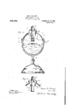
- Figure 1 is a front elevation of my de- Vice in portable form
- Fig 2 is a sectional view on the line mm of Fig. 1, omitting the bracket
- Fig. 3 is a similar sectional view of a modified detail.
- bracket arms, 2 upon the extremities of which are hearings to receive the pivots 3, on which the receptacle 4 is mounted so as to be capable of tilting in a well known manner.
- the receptacle may be of any material, but glass is preferred, andthe general shape is approximately globular as shown.
- Two circular headings, 5, 6, surround the recep 'tacle in the middle save where the lower beading is interrupted for a short space in front as shown in Figs. 1 and 2 at 7.
- the beading is preferably cast or molded so .as to form a partof the receptacle.
- a metal supporting band 8 closely surrounds the receptacle, fitting between the beadings 5 and 6 as shown.
- This band is composed of two semi-circular parts Whose ends are brought together at the two sides and joined in any convenient manner. In the form shown this is accomplished by means of sleeves 9 (see 1).
- the front of the supporting band is provided with a tilting shelf which projects a short distance downward and then forward a greater distance, asshown at 10 in Figs. 1 and 2. It is against this shelf that the users finger tips are pressed in using the device, as is already known in the art. It is a novel feature of my invention, however, to combine a shelf made substantially as described with the supporting band and to locate it between the ends of the interrupted heading 6 as shown.
- the socket 1 3 also supports a tu'be l6, closed at its normally lower end and prodown into the rec iving cap 12. to which the pan 1% and tube 16 vided with slots or openings 17, for admis sion of liquid.
- the tube 16 is surrounded by the measuring pan 18, the upper edge of which fits within the front of the neck 11,
- the bottom of the receptacle is made thicker than the remainder, so that the extra it returns to normal position.
- the liquid tlows back in the direction opposite to the interior (LII'OWHIII 1? 1g. 2, leaving behind a certain small-amount which is caught by the pan l8, and the quantity of which is de termined by the sizejotsaid pan.
- This measured quantity of liquid flows through the slots 17 into the tube 16.
- the receptacle is next tilted the liquid in the pally vthat ol,
- the l'unction o't the plunger 20 is princian automatic valve, its. only other lfuncti'on 'being carried out by the pointed tip'2l whicliis preferably provided,
- l ig 3 shows an instance ol a modified form of valve-useful in my-invcntion.
- the ball 22 is provided as a substitute torthe plunger and serves to close the" nipple at the pro ee'tiini by dropping into the position shown in the drawing.
- a device of the class described comprising a receptacle having a heading ex tending atvone point and a pivotally mounted suppartly around it so as to leave a gap porting band fitting the receptacle above said beading and having a projection extending downward through said gap and then outward to form a-tilting shell", substantially as described.
- a device oi" the class described comprising a tilting receptacle having charge opening located at its'top when the receptacle is in normal position, a discharge tube open at both ends and fixed directly under said opening, and means near the .lower opening of said tube for retaining 'and delivering to said tube a measured quanv tity of liquid each time the receptacle is tilted and delivering the same to said tube the next time the receptacle is tilted, substantially as described.
- Av device of the class described com-- prising a tilting receptacle having a dis- I charge opening located at its top when said receptacle is in normal position, and means within thereceptacle just under said-opening for catching a limited quantity ot'liquid each time the receptacle is tilted and delivering the same to said discharge opening the next time the'receptacle is tilted, substantially as described.
- a device of the class described comprising a tilting receptacle having a neck at The use of I a dis-- its top, a receiving cap fitting said neck and having an opening, a tube W1th1n said receptacle and belnndsaid opening and supported by said cap, said tube being closed save near its top and an automatic valve for closing communication between said tube and said discharge opening When the receptacle is inverted, substantially as described.
- a device of the class described comprising a tilting receptacle having a dis charge opening, a slotted tube within the receptacle behind said opening and a measuring pan surrounding said tube and so located as to discharge its contents into said tube through the slots therein when the re ceptacle assumes its normal position, substantially as described.
- a device of the class described coniprising a tilting receptacle having a neck at its top, a receiving cap havlng an opening and fitted on said neck, a measuring pan fitted into said neck Within the receptacle and a tube closed save near its top extending inward from said opening and placed so as to receive the contents of said measuring pan when the receptacle assumes its normal position, substantially as described.
- a device of the class described comprising a tilting receptacle having an opening, a tube extending into said receptacle Within said opening and a measuring pan open on one side only, surrounding said tube and placed so as to discharge its contents into said tube when the receptacle assumes its normal position, substantially as described.
Landscapes
- Engineering & Computer Science (AREA)
- Mechanical Engineering (AREA)
- Health & Medical Sciences (AREA)
- Public Health (AREA)
- Devices For Dispensing Beverages (AREA)
Description
Patented Oct. 12, 1909.
2 SHEETS-SHEET 1.
M. M. MARCUSE.
LIQUID DISPENSING DEVICE.
APPLICATION FILED JAN. 9, 1908.
Patented Oct. 12,1909.
2 SHEETS-SHEET 2.
M W W UNITED STATES PATENT OFFICE.
MOSES Mi MARCUS'E, on NEW YORK, N. Y.
.LIQUID-DISPENSING DEVICE. 7
Specification of Letters Patent.
- Patented Oct. 12, 1909.
Application filed January 9, 1908. Serial No. 410,017.
provements in that class of liquid soap dispensers which comprise a plvoted receptacle for the soap solution arranged to be tilted or turned over so that a certain quantity of liquid soap is discharged into the hands of the user.
As hitherto'constructed, a slidin weightcd plunger has been employed in evices of this character, and this has been so arranged as to slide down to the discharge orifice with the intention of positively ejecting a pre determined quantity of liquid therefrom and at the same time preventing the liquid from continuing to run out after the proper quantity of soap for one use has been discharged. In order to make it possible to use the device even after the supply of soap has become low, there has been used a slotted tube extending inward from the discharge opening across to the bottom of the receptacle. This tube is intended to act as a scoop, gathering up the liquid at the bottom as the receptacle is inverted and conveying it to the opening. At the same time it acts as a guide for the weighted plunger above mentioned. It has been found that the shaking of the soap solution due to normal operation of the device is very apt to produce foam or suds. This gets into the scooping tube above mentimed and interferes with proper use of the device. Moreover the receptacle must be carefully made. to avoid irregularities in thickness at the bottom which create'difiiculty in proper fitting of scooping tubesof uniform length. This difiiculty is particularly felt where the'aecept-acle is made of glass, and, as this material has been found to be the best for various reasons, the (11S- advantage mentioned has proven embarassmg.
The present invention, while avoiding the difliculties above'mentioned, and also comprising an improved construction especially fitted for use with glass receptacles, has further relation to an improved means for disliquid.
charging a previously measured quantity of Further advantages of this invention are set forth in my specification and claims.
A preferred form of this invention is illustrated in the accompanying drawings,
wherein Figure 1 is a front elevation of my de- Vice in portable form, Fig 2 is a sectional view on the line mm of Fig. 1, omitting the bracket, and Fig. 3 is a similar sectional view of a modified detail.
Upon the base, 1, are mounted bracket arms, 2, upon the extremities of which are hearings to receive the pivots 3, on which the receptacle 4 is mounted so as to be capable of tilting in a well known manner.
The receptacle may be of any material, but glass is preferred, andthe general shape is approximately globular as shown. Two circular headings, 5, 6, surround the recep 'tacle in the middle save where the lower beading is interrupted for a short space in front as shown in Figs. 1 and 2 at 7. The beading is preferably cast or molded so .as to form a partof the receptacle.
A metal supporting band 8 closely surrounds the receptacle, fitting between the beadings 5 and 6 as shown. This band is composed of two semi-circular parts Whose ends are brought together at the two sides and joined in any convenient manner. In the form shown this is accomplished by means of sleeves 9 (see 1). The front of the supporting band is provided with a tilting shelf which projects a short distance downward and then forward a greater distance, asshown at 10 in Figs. 1 and 2. It is against this shelf that the users finger tips are pressed in using the device, as is already known in the art. It is a novel feature of my invention, however, to combine a shelf made substantially as described with the supporting band and to locate it between the ends of the interrupted heading 6 as shown. By so placing the tilting shelf, rotation of the receptacle within the band 8 is prevented and proper position of the pan hereinafter described is inejected. The socket 1 3 also supports a tu'be l6, closed at its normally lower end and prodown into the rec iving cap 12. to which the pan 1% and tube 16 vided with slots or openings 17, for admis sion of liquid. The tube 16 is surrounded by the measuring pan 18, the upper edge of which fits within the front of the neck 11,
but is cutaway at the rear so as to'leave a wide opening, as shown at 15).
The bottom of the receptacle is made thicker than the remainder, so that the extra it returns to normal position. The liquid tlows back in the direction opposite to the interior (LII'OWHIII 1? 1g. 2, leaving behind a certain small-amount which is caught by the pan l8, and the quantity of which is de termined by the sizejotsaid pan. This measured quantity of liquid flows through the slots 17 into the tube 16. 'lVhen the receptacle is next tilted the liquid in the pally vthat ol,
"obstruction.
As the main body of liquid runs down each time, the foam it any, remains on top and, as the liquid collected in each instance comes from the bottom of the liquid body, no foam will lind its into the nipple 14.
The l'unction o't the plunger 20, is princian automatic valve, its. only other lfuncti'on 'being carried out by the pointed tip'2l whicliis preferably provided,
and acts to li'ecp the opening 15,;free from Where this last fnan'ual function is'not deemed essential, other forms of automatic valve may be used.
l ig 3 shows an instance ol a modified form of valve-useful in my-invcntion. Here the ball 22 is provided as a substitute torthe plunger and serves to close the" nipple at the pro ee'tiini by dropping into the position shown in the drawing.
For the purpose ol' my present invention it is not -sen'tial that a heavy plunger or ball be useth'as this element is not relied the shelf 10 is discontinued and the receptacle is released,
upon 0 eject the liquid from the measuring ch; mber ot predetermined size. Indeed, it is an advantageto use a rather light stopper,
(20, so that the liquid in the tube 16 may be sure to retard it and prevent its stopping the discharge opening too soon.
' It will be seenthat the construction substantially as herein described is perfectly adapted for use in connection with glass. receptacles 4, inasmuch as it is not dependent upon a nice adjustment of proportions and din'iensions, which is not procurable in glass articles without great expense. glass in this coni'iection is that it is not only inexpensive, but also makes it possible to see at a glance when the receptacle requires l'tjplel'llSllll'glg'.
VariousQichanges can be made in this apparatus without departing from my invention, and l jam not to be ui'iderstood as limiting inyseltif to the details herein shown and described.
hat I claim is- I 1. A device of the class described com prising a receptacle having an exterior groove surrouiuling it and a pivotally mounted supporting band in sait groove having a projection passing out of the groove through a gap in one edge, said projection also extending outward fronrsaid vessel so as to serve as a tilting shelf for the receptacle, substantially as described.
2. A device of the class described comprising a receptacle having a heading ex tending atvone point and a pivotally mounted suppartly around it so as to leave a gap porting band fitting the receptacle above said beading and having a projection extending downward through said gap and then outward to form a-tilting shell", substantially as described.
A device oi" the class described comprising a tilting receptacle having charge opening located at its'top when the receptacle is in normal position, a discharge tube open at both ends and fixed directly under said opening, and means near the .lower opening of said tube for retaining 'and delivering to said tube a measured quanv tity of liquid each time the receptacle is tilted and delivering the same to said tube the next time the receptacle is tilted, substantially as described.
'4.. Av device of the class described com-- prising a tilting receptacle having a dis- I charge opening located at its top when said receptacle is in normal position, and means within thereceptacle just under said-opening for catching a limited quantity ot'liquid each time the receptacle is tilted and delivering the same to said discharge opening the next time the'receptacle is tilted, substantially as described.
5. A device of the class described comprising a tilting receptacle having a neck at The use of I a dis-- its top, a receiving cap fitting said neck and having an opening, a tube W1th1n said receptacle and belnndsaid opening and supported by said cap, said tube being closed save near its top and an automatic valve for closing communication between said tube and said discharge opening When the receptacle is inverted, substantially as described. (S. A device of the class described comprising a tilting receptacle having a dis charge opening, a slotted tube within the receptacle behind said opening and a measuring pan surrounding said tube and so located as to discharge its contents into said tube through the slots therein when the re ceptacle assumes its normal position, substantially as described.
7. A device of the class described coniprising a tilting receptacle having a neck at its top, a receiving cap havlng an opening and fitted on said neck, a measuring pan fitted into said neck Within the receptacle and a tube closed save near its top extending inward from said opening and placed so as to receive the contents of said measuring pan when the receptacle assumes its normal position, substantially as described.
8. A device of the class described comprising a tilting receptacle having an opening, a tube extending into said receptacle Within said opening and a measuring pan open on one side only, surrounding said tube and placed so as to discharge its contents into said tube when the receptacle assumes its normal position, substantially as described.
MOSES M. MARC/USE. Witnesses H, S. MnoKAYn, M. S. BUTLER.
Priority Applications (1)
| Application Number | Priority Date | Filing Date | Title |
|---|---|---|---|
| US41001708A US936334A (en) | 1908-01-09 | 1908-01-09 | Liquid-dispensing device. |
Applications Claiming Priority (1)
| Application Number | Priority Date | Filing Date | Title |
|---|---|---|---|
| US41001708A US936334A (en) | 1908-01-09 | 1908-01-09 | Liquid-dispensing device. |
Publications (1)
| Publication Number | Publication Date |
|---|---|
| US936334A true US936334A (en) | 1909-10-12 |
Family
ID=3004756
Family Applications (1)
| Application Number | Title | Priority Date | Filing Date |
|---|---|---|---|
| US41001708A Expired - Lifetime US936334A (en) | 1908-01-09 | 1908-01-09 | Liquid-dispensing device. |
Country Status (1)
| Country | Link |
|---|---|
| US (1) | US936334A (en) |
Cited By (2)
| Publication number | Priority date | Publication date | Assignee | Title |
|---|---|---|---|---|
| US2919056A (en) * | 1956-02-20 | 1959-12-29 | Pressure Dispensers Inc | Liquid measuring device |
| US3163335A (en) * | 1962-04-27 | 1964-12-29 | Story F Chappell | Tiltable measuring dispenser |
-
1908
- 1908-01-09 US US41001708A patent/US936334A/en not_active Expired - Lifetime
Cited By (2)
| Publication number | Priority date | Publication date | Assignee | Title |
|---|---|---|---|---|
| US2919056A (en) * | 1956-02-20 | 1959-12-29 | Pressure Dispensers Inc | Liquid measuring device |
| US3163335A (en) * | 1962-04-27 | 1964-12-29 | Story F Chappell | Tiltable measuring dispenser |
Similar Documents
| Publication | Publication Date | Title |
|---|---|---|
| US3023937A (en) | Measuring dispenser | |
| US406017A (en) | Label attachment for bottles | |
| US845175A (en) | Bottle. | |
| US2318812A (en) | Measuring and dispensing device for packaged material | |
| US2626089A (en) | Powdered and granulated material container with self-closing dispensing valve | |
| US2123606A (en) | Dispensing device | |
| US3276637A (en) | Dispenser for particulate material | |
| US1941786A (en) | Portable hand toothpowder dispenser | |
| US3344962A (en) | Dispensing device | |
| US2770398A (en) | Device for dispensing measured quantities of coffee | |
| US1369740A (en) | Rotary measuring device | |
| US2561721A (en) | Device for dispensing measured quantities of granular materials | |
| US1332476A (en) | Dispensing-receptacle | |
| US1311227A (en) | Haws hartmajit | |
| US1642678A (en) | Sugar-dispensing receptacle | |
| US548123A (en) | Bottle or jug filling apparatus | |
| US1813131A (en) | Dispensing receptacle | |
| US1377801A (en) | Self-closing container | |
| US1383935A (en) | Tobacco-receptacle | |
| US28726A (en) | Spout and side of pitchers | |
| USRE20592E (en) | Ashtray | |
| US1141368A (en) | Sugar-bowl. | |
| US1482126A (en) | Combined measuring and dispensing device | |
| US1294056A (en) | Dispenser. | |
| US2236018A (en) | Pitcher |