US9362869B2 - Signal predistortion for non-linear amplifier - Google Patents
Signal predistortion for non-linear amplifier Download PDFInfo
- Publication number
- US9362869B2 US9362869B2 US14/232,071 US201114232071A US9362869B2 US 9362869 B2 US9362869 B2 US 9362869B2 US 201114232071 A US201114232071 A US 201114232071A US 9362869 B2 US9362869 B2 US 9362869B2
- Authority
- US
- United States
- Prior art keywords
- linear amplifier
- factors
- effect
- coefficients
- signal
- Prior art date
- Legal status (The legal status is an assumption and is not a legal conclusion. Google has not performed a legal analysis and makes no representation as to the accuracy of the status listed.)
- Expired - Fee Related
Links
- 230000000694 effects Effects 0.000 claims abstract description 42
- 230000005540 biological transmission Effects 0.000 claims abstract description 32
- 238000000034 method Methods 0.000 claims abstract description 22
- 238000004590 computer program Methods 0.000 claims abstract description 18
- 230000002301 combined effect Effects 0.000 claims abstract description 17
- 230000006870 function Effects 0.000 claims description 37
- 239000011159 matrix material Substances 0.000 claims description 27
- 239000013598 vector Substances 0.000 claims description 21
- 238000013178 mathematical model Methods 0.000 claims description 9
- 238000007620 mathematical function Methods 0.000 claims 2
- 238000004422 calculation algorithm Methods 0.000 description 15
- 238000012545 processing Methods 0.000 description 9
- 238000010586 diagram Methods 0.000 description 8
- 230000008569 process Effects 0.000 description 6
- 230000006386 memory function Effects 0.000 description 4
- 239000000969 carrier Substances 0.000 description 3
- 230000003068 static effect Effects 0.000 description 3
- 101100072620 Streptomyces griseus ind2 gene Proteins 0.000 description 2
- 238000013459 approach Methods 0.000 description 2
- 230000010267 cellular communication Effects 0.000 description 2
- 238000004891 communication Methods 0.000 description 2
- 230000001419 dependent effect Effects 0.000 description 2
- 238000010295 mobile communication Methods 0.000 description 2
- 230000009467 reduction Effects 0.000 description 2
- 238000012546 transfer Methods 0.000 description 2
- 230000004913 activation Effects 0.000 description 1
- 230000003321 amplification Effects 0.000 description 1
- 230000008859 change Effects 0.000 description 1
- 238000011161 development Methods 0.000 description 1
- 238000005516 engineering process Methods 0.000 description 1
- 230000014509 gene expression Effects 0.000 description 1
- 230000007774 longterm Effects 0.000 description 1
- 238000005259 measurement Methods 0.000 description 1
- 238000003199 nucleic acid amplification method Methods 0.000 description 1
- 230000010363 phase shift Effects 0.000 description 1
- 238000002360 preparation method Methods 0.000 description 1
- 230000008707 rearrangement Effects 0.000 description 1
- 230000004044 response Effects 0.000 description 1
Images


Classifications
-
- H—ELECTRICITY
- H03—ELECTRONIC CIRCUITRY
- H03F—AMPLIFIERS
- H03F1/00—Details of amplifiers with only discharge tubes, only semiconductor devices or only unspecified devices as amplifying elements
- H03F1/32—Modifications of amplifiers to reduce non-linear distortion
- H03F1/3241—Modifications of amplifiers to reduce non-linear distortion using predistortion circuits
- H03F1/3247—Modifications of amplifiers to reduce non-linear distortion using predistortion circuits using feedback acting on predistortion circuits
-
- H—ELECTRICITY
- H03—ELECTRONIC CIRCUITRY
- H03F—AMPLIFIERS
- H03F1/00—Details of amplifiers with only discharge tubes, only semiconductor devices or only unspecified devices as amplifying elements
- H03F1/30—Modifications of amplifiers to reduce influence of variations of temperature or supply voltage or other physical parameters
-
- H—ELECTRICITY
- H03—ELECTRONIC CIRCUITRY
- H03F—AMPLIFIERS
- H03F1/00—Details of amplifiers with only discharge tubes, only semiconductor devices or only unspecified devices as amplifying elements
- H03F1/32—Modifications of amplifiers to reduce non-linear distortion
- H03F1/3241—Modifications of amplifiers to reduce non-linear distortion using predistortion circuits
- H03F1/3258—Modifications of amplifiers to reduce non-linear distortion using predistortion circuits based on polynomial terms
-
- H—ELECTRICITY
- H03—ELECTRONIC CIRCUITRY
- H03F—AMPLIFIERS
- H03F1/00—Details of amplifiers with only discharge tubes, only semiconductor devices or only unspecified devices as amplifying elements
- H03F1/32—Modifications of amplifiers to reduce non-linear distortion
- H03F1/3241—Modifications of amplifiers to reduce non-linear distortion using predistortion circuits
- H03F1/3282—Acting on the phase and the amplitude of the input signal
-
- H—ELECTRICITY
- H03—ELECTRONIC CIRCUITRY
- H03F—AMPLIFIERS
- H03F3/00—Amplifiers with only discharge tubes or only semiconductor devices as amplifying elements
- H03F3/189—High-frequency amplifiers, e.g. radio frequency amplifiers
- H03F3/19—High-frequency amplifiers, e.g. radio frequency amplifiers with semiconductor devices only
- H03F3/195—High-frequency amplifiers, e.g. radio frequency amplifiers with semiconductor devices only in integrated circuits
-
- H—ELECTRICITY
- H03—ELECTRONIC CIRCUITRY
- H03F—AMPLIFIERS
- H03F3/00—Amplifiers with only discharge tubes or only semiconductor devices as amplifying elements
- H03F3/20—Power amplifiers, e.g. Class B amplifiers, Class C amplifiers
- H03F3/24—Power amplifiers, e.g. Class B amplifiers, Class C amplifiers of transmitter output stages
-
- H—ELECTRICITY
- H04—ELECTRIC COMMUNICATION TECHNIQUE
- H04L—TRANSMISSION OF DIGITAL INFORMATION, e.g. TELEGRAPHIC COMMUNICATION
- H04L27/00—Modulated-carrier systems
- H04L27/32—Carrier systems characterised by combinations of two or more of the types covered by groups H04L27/02, H04L27/10, H04L27/18 or H04L27/26
- H04L27/34—Amplitude- and phase-modulated carrier systems, e.g. quadrature-amplitude modulated carrier systems
- H04L27/36—Modulator circuits; Transmitter circuits
- H04L27/366—Arrangements for compensating undesirable properties of the transmission path between the modulator and the demodulator
- H04L27/367—Arrangements for compensating undesirable properties of the transmission path between the modulator and the demodulator using predistortion
- H04L27/368—Arrangements for compensating undesirable properties of the transmission path between the modulator and the demodulator using predistortion adaptive predistortion
-
- H—ELECTRICITY
- H03—ELECTRONIC CIRCUITRY
- H03F—AMPLIFIERS
- H03F2200/00—Indexing scheme relating to amplifiers
- H03F2200/336—A I/Q, i.e. phase quadrature, modulator or demodulator being used in an amplifying circuit
-
- H—ELECTRICITY
- H03—ELECTRONIC CIRCUITRY
- H03F—AMPLIFIERS
- H03F2200/00—Indexing scheme relating to amplifiers
- H03F2200/447—Indexing scheme relating to amplifiers the amplifier being protected to temperature influence
-
- H—ELECTRICITY
- H03—ELECTRONIC CIRCUITRY
- H03F—AMPLIFIERS
- H03F2200/00—Indexing scheme relating to amplifiers
- H03F2200/451—Indexing scheme relating to amplifiers the amplifier being a radio frequency amplifier
-
- H—ELECTRICITY
- H03—ELECTRONIC CIRCUITRY
- H03F—AMPLIFIERS
- H03F2201/00—Indexing scheme relating to details of amplifiers with only discharge tubes, only semiconductor devices or only unspecified devices as amplifying elements covered by H03F1/00
- H03F2201/32—Indexing scheme relating to modifications of amplifiers to reduce non-linear distortion
- H03F2201/3209—Indexing scheme relating to modifications of amplifiers to reduce non-linear distortion the amplifier comprising means for compensating memory effects
-
- H—ELECTRICITY
- H03—ELECTRONIC CIRCUITRY
- H03F—AMPLIFIERS
- H03F2201/00—Indexing scheme relating to details of amplifiers with only discharge tubes, only semiconductor devices or only unspecified devices as amplifying elements covered by H03F1/00
- H03F2201/32—Indexing scheme relating to modifications of amplifiers to reduce non-linear distortion
- H03F2201/3212—Using a control circuit to adjust amplitude and phase of a signal in a signal path
-
- H—ELECTRICITY
- H03—ELECTRONIC CIRCUITRY
- H03F—AMPLIFIERS
- H03F2201/00—Indexing scheme relating to details of amplifiers with only discharge tubes, only semiconductor devices or only unspecified devices as amplifying elements covered by H03F1/00
- H03F2201/32—Indexing scheme relating to modifications of amplifiers to reduce non-linear distortion
- H03F2201/3224—Predistortion being done for compensating memory effects
-
- H—ELECTRICITY
- H03—ELECTRONIC CIRCUITRY
- H03F—AMPLIFIERS
- H03F2201/00—Indexing scheme relating to details of amplifiers with only discharge tubes, only semiconductor devices or only unspecified devices as amplifying elements covered by H03F1/00
- H03F2201/32—Indexing scheme relating to modifications of amplifiers to reduce non-linear distortion
- H03F2201/3227—Adaptive predistortion based on amplitude, envelope or power level feedback from the output of the main amplifier
-
- H—ELECTRICITY
- H03—ELECTRONIC CIRCUITRY
- H03F—AMPLIFIERS
- H03F2201/00—Indexing scheme relating to details of amplifiers with only discharge tubes, only semiconductor devices or only unspecified devices as amplifying elements covered by H03F1/00
- H03F2201/32—Indexing scheme relating to modifications of amplifiers to reduce non-linear distortion
- H03F2201/3233—Adaptive predistortion using lookup table, e.g. memory, RAM, ROM, LUT, to generate the predistortion
Definitions
- the invention relates to the field of signal processing and, particularly, to predistorting a signal in an electronic device.
- Non-linear amplifier is a power amplifier which is a component of a radio transmitter circuitry that amplifies a transmission signal for radio transmission.
- Characteristics of the non-linear amplifiers depend on several external factors that may be understood as working conditions of the non-linear amplifier. Such working conditions may include a power supply voltage, a bias voltage, and temperature. Varying working conditions cause variance in the operational characteristics of the non-linear amplifier, e.g. in linearity of the amplifier. Therefore, different working conditions may cause the amplifier to distort an amplified signal differently.
- an apparatus as specified in claim 14 .
- an apparatus as specified in claim 28 there is provided an apparatus as specified in claim 28 .
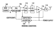
- FIG. 1 illustrates a general block diagram of a radio transmitter comprising predistortion elements according to embodiments of the invention
- FIG. 2 illustrates predistortion according to an embodiment
- FIG. 3 illustrates the distortion and compensation according to an embodiment of the invention
- FIG. 4 illustrates a block diagram of an apparatus configured to carry out a predistortion algorithm according to an embodiment of the invention
- FIG. 5 illustrates a flow diagram of a process for computing predistortion coefficients according to an embodiment of the invention
- FIG. 6 illustrates a block diagram of another circuitry for predistorting a transmission signal in a radio transmitter according to an embodiment of the invention
- FIGS. 7A, 7B, 8A, and 8B illustrate embodiments for reducing complexity of the predistortion algorithm
- FIG. 9 illustrates an embodiment for scaling the transmission signal according to an embodiment of the invention.
- FIG. 1 is a block diagram illustrating components of a radio transmitter according to an embodiment of the invention.
- the radio transmitter may be a mobile communication device, for example.
- the block diagram of FIG. 1 illustrates components related to predistortion and power amplification of a transmission signal. All of the components illustrated in FIG. 1 are obviously not necessary for carrying out the invention, and the radio transmitter may comprise additional components.
- a modulation source 102 provides a transmission signal comprising information symbols to be transmitted from the radio transmitter to a radio receiver.
- the transmission signal may be in a digital form and divided into an in-phase (I) component and a quadrature (Q) component.
- the transmission signal is then fed to a predistortion unit 106 .
- the predistortion unit 106 receives the I and Q components of the transmission signal output from modulation source 102 . Additionally, the predistortion unit 106 receives weighting coefficients from a computation algorithm circuitry 120 configured to control the predistortion.
- the computation algorithm circuitry 120 may have knowledge on the amplitude and phase distortion properties of a power amplifier 116 and it may predistort the transmission signal (I and Q component) by computing the weighting coefficients that compensate for the distortion caused by the power amplifier 116 .
- the operation of the computation algorithm circuitry 120 will be described in detail below.
- the predistortion unit 106 outputs the predistorted transmission signal into an I/Q D/A converter 110 .
- the I/Q D/A converter 110 converts the digital I and Q components into analog signals and feeds them to an I/Q modulator 112 .
- the I/Q modulator 112 converts the baseband analog I and Q components of the transmission signal into a radio frequency (RF) transmission signal.
- RF radio frequency
- the I/Q modulator 112 modulates a carrier signal according to the information contained in the I or Q component of the transmission signal.
- a separate carrier is modulated for each I and Q component and a phase shift between the two carriers is typically 90 degrees.
- the carriers are then summed together to provide the RF transmission signal.
- the RF transmission signal is then fed to the power amplifier 116 .
- the power amplifier 116 receives a power supply voltage from a power supply voltage generator, which may be a switched-mode power supply (SMPS), for example.
- SMPS switched-mode power supply
- the power amplifier 116 then amplifies the transmission signal according to the power supply voltage provided by the power supply voltage generator and applies the power-amplified transmission signal to radio frequency (RF) front-end components 118 for transmission through an antenna, for example.
- RF radio frequency
- Elements processing digital baseband signals according to FIG. 1 may be implemented in one or more processing units configured by suitable software, application-specific integrated circuits (ASICs), and/or as separate logic circuits, for example.
- ASICs application-specific integrated circuits
- one aspect in the predistortion of the transmission signal is to negate the signal distortion caused by the power amplifier. Therefore, a distortion model of the power amplifier is estimated.
- x denotes an input signal of the power amplifier 116 , e.g. a multi-carrier transmission signal
- y denotes an output signal of the power amplifier 116 .
- the input signal x is also fed to the predistortion circuitry 200 .
- a summer 202 computes a difference between the outputs of the power amplifier and the estimated distortion model as computed by the predistortion circuitry 200 .
- NLM(x) a non-linear memory function of x.
- the function f i (x) may define base functions for the NLM, and they may be selected according to the series representation.
- Coefficients a i define the predistortion of the transmission signal, and they may be computed such that the predistortion compensates for the distortion caused by the power amplifier 116 in its current operational environment. As a consequence, the coefficients a i may be acquired as a result of minimizing the above-mentioned cost function.
- the cost function is the norm of NLM ⁇ y as ⁇ f(x,a) ⁇ y ⁇ (4) or Euclidean norm ⁇ f(x,a) ⁇ y ⁇ 2 (5)
- NLM is expanded as:
- Parameters p ⁇ represent different working conditions, e.g.
- Equation (6) any one of the working conditions may be time-variant, and the time-variance may be included in the NLM by making the functions g ⁇ time-variant.
- a time-variant working condition is the temperature.
- FIG. 3 illustrates an equivalent block diagram for Equation (6), wherein the coefficients a 0, 0 to a i, ⁇ are computed to compensate for the distortion caused by the working conditions affecting the power amplifier, that is the distortion caused by functions g ⁇ .
- FIG. 3 illustrates a block diagram of the contribution of different working conditions represented by blocks 300 and 320 , each for one working condition, on the signal distortion of the power amplifier.
- the contribution of each working condition 300 , 320 may be represented by a transfer function.
- the corresponding transfer function is time-variant as well.
- Elements 340 , 360 represent base functions that are used to represent any non-linear memory function of the input signal x.
- the base functions 340 , 360 may be polynomial functions, series functions, delay elements, look-up tables etc.
- Coefficients a 0, 0 to a i, ⁇ represent the predistortion coefficients that are computed according to embodiments of the invention to compensate for the distortion caused by blocks 300 , 320 .
- Each base function 340 , 360 is multiplied by a respective coefficients a 0, 0 to a i, ⁇ , wherein a base function f 0 shown by block 340 is multiplied by coefficients a 0, 0 to a 0, ⁇ , a base function fi shown by block 360 is multiplied by coefficients a i, 0 to a i, ⁇ , and so on.
- Each thus predistorted base function is then multiplied with a respective output of each predistortion function 300 , 320 , as shown in FIG. 3 .
- the resulting signals are then summed in an adder 380 , and in an optimum case, the result minus y is zero in case of optimal estimation of the predistortion parameter.
- the cost functions (4) and (5) are expanded as: ⁇ f(x, a, p) ⁇ y ⁇ (7) and ⁇ f(x, a, p) ⁇ y ⁇ 2 (8)
- the effect of the temperature on the signal distortion is in this case negligible (constant), while the supply and the gate voltage distort the signal in this case linearly (the supply voltage) and quadratically (the gate voltage).
- the number of working conditions may be arbitrary depending on which working conditions are selected to be taken into account in the NLM model, and the distortion functions g ⁇ may be more complex than that used as the example in Equation (9), e.g. polynomial functions.
- both distortion functions g 1 an g 2 depend on the same variable V, but differently. It should, however, be appreciated that this is just an illustrative example selected for the sake of clarity of the description, and they may depend on different variables.
- Equation (10) may be written into a matrix form of X ⁇ e
- operation X*X may be computed as an autocorrelation operation which represents the autocorrelation of the effect of the working conditions.
- the operation X*y may be computed as a cross-correlation operation which represents the cross-correlation between the effect of the working conditions and the output of the power amplifier.
- the model coefficient can be calculated by: a i
- embodiments of the invention compute a model representing mathematically an effect of a plurality of factors (the above-mentioned working conditions) on signal distortion caused by the power amplifier.
- the contribution of each factor may be derived beforehand through measurements, for example, and then approximated as the mathematical representation of Equation (9) that provides an approximation of the effect of the factor.
- a global model which incorporates a combined effect of the plurality of factors on the signal distortion caused by the power amplifier may be computed.
- embodiments of the present invention provide a global optimized model providing predistortion coefficients that compensate for the combined effect of the plurality of working conditions in a single mathematical model.
- the global model may be configured to take into account all working conditions that affect the signal distortion properties of the power amplifier, and the coefficients for such a global model may be derived by minimizing Equation (15) which yields Equation (16).
- Some conventional solutions store a table of coefficients for each working condition separately, and the predistortion coefficients are read from such a look-up table.
- Such tables provide a local discrete model for each coefficient, and taking into account the combined effect of the plurality of working conditions increases the size of the look-up tables exponentially in proportion to the number of the working conditions. Additionally, the working conditions have to be quantized to a certain degree which reduces accuracy.
- values representing the current working conditions may simply be added to the global model, and the predistortion coefficients may be computed by minimizing Equation (15). Since no extensive look-up tables are needed, the present invention reduces the memory requirements. Additionally, an accurate global model is provided that represents the combined effect of the different working conditions, and the predistortion coefficients may be computed under arbitrary working conditions. Furthermore, as there is no need for quantizing the effect of the working conditions, the accuracy of the model is improved with respect to conventional look-up tables.
- the number of computed predistortion coefficients may be reduced to match with the accuracy of the model representing the distortion properties caused by the working conditions.
- the number of coefficients computed may be defined as proportional to the complexity of the mathematical representation of the effect of said plurality of working conditions.
- the number of computed coefficients may be designed to roughly match with the order of the mathematical representation of the effect of the working conditions. For example, if the effect of a given working condition is of second order, e.g. V 2 , the number of computed coefficients may be 2, 3, or 4.
- the number of computed coefficients may be reduced from a maximum number of computed coefficients as low as the order of representation of the working condition (or slightly more than that, e.g. one or two coefficients more than said order). This may be achieved by reducing the number of base functions included in the computation, as defined by index1 and index2.
- the values of indices index1 and index2 may be determined separately, and they may have different values, thus providing flexibility to the computation.
- Equation (22) a combined autocorrelation matrix R yyz and a combined cross-correlation vector r yzz similar to that of Equation (16) may be derived as follows:
- R yyz the size of the combined autocorrelation matrix
- the size of the combined cross-correlation vector may be reduced accordingly. This may be achieved by eliminating least-significant samples or sub-matrix elements of the combined autocorrelation matrix and the combined cross-correlation vector, as illustrated in FIGS. 7A and 7B .
- FIG. 7A illustrates as diagonal lining elements removed from the combined autocorrelation matrix
- FIG. 7B illustrates as diagonal lining those elements removed from the combined cross-correlation vector.
- this may be achieved according to Equation (19) by limiting the number of rows and columns of at least some of sub-matrices of the combined autocorrelation matrix R yyz and the number of elements of at least some of the sub-vectors of the combined cross-correlation vector from n to ind1/ind2. This results in a reduced combined autocorrelation matrix and a reduced combined cross-correlation vector as follows:
- R yyz [ R yy ⁇ ( n , n ) ⁇ ⁇ ⁇ V dd ⁇ R yy ⁇ ( n , ind ⁇ ⁇ 1 ) ⁇ ⁇ ⁇ V dd 2 ⁇ R yy ⁇ ( n , ind ⁇ ⁇ 2 ) ⁇ ⁇ ⁇ V dd ⁇ R yy ⁇ ( ind ⁇ ⁇ 1 , n ) ⁇ ⁇ ⁇ V dd 2 ⁇ R yy ⁇ ( ind ⁇ ⁇ 1 , ind ⁇ ⁇ 1 ) ⁇ ⁇ ⁇ V dd 3 ⁇ R yy ⁇ ( ind ⁇ ⁇ 1 , ind ⁇ ⁇ 2 ) ⁇ ⁇ ⁇ V dd 2 ⁇ R yy ⁇ ( ind ⁇ ⁇ 2 , n ) ⁇ ⁇ ⁇ V dd 3 ⁇ R yy ⁇ ( ind ⁇ ⁇ 1
- FIGS. 8A and 8B illustrate another embodiment where the elements are not removed at the end of each sub-matrix of the combined autocorrelation matrix and sub-vector of the combined cross-correlation vector, as was done in the embodiment of FIGS. 7A and 7B . Instead, the elements are removed selectively from inside of the sub-matrices and sub-vectors. This may be achieved by defining a step size w (integer greater than 1) that is introduced in the sum operations of Equation (19).
- index i in Equation (19) runs from zero to n in step sizes defined by w.
- index i in Equation (19) runs from one to n in step sizes defined by w.
- index i in Equation (19) runs from w to n in step sizes defined by w.
- the sub-element consisting of the basic autocorrelation sub-matrix R yy (n, n) and the basic cross-correlation vector r yy (n) may be left intact, and they may be bypassed in the reduction of elements. In other words, those sub-elements that are not scaled by the working conditions may be bypassed in the reduction of elements.
- the combined autocorrelation matrices and the combined cross-correlation vectors may be summed over all values of each working condition to provide an autocorrelation matrix and a cross-correlation vector which averages the effect of varying values of each working condition, e.g. over all values of the drain voltage V dd , thus resulting in:
- R yyzsum ⁇ V dd R yyz ( V dd )
- r yzzsum ⁇ V dd r yzz ( V dd )
- the summation over all the values of each working condition may be omitted, and the coefficients may be recomputed during the operation, e.g. upon a detected change in at least one of the working conditions included in the model.
- the number of weighting coefficients computed by the algorithm 120 may be dependent on the working conditions, e.g. the amplitude of the power supply voltage of the power amplifier and the amplitude of the input signal x of the predistortion circuitry 106 .
- the input signal x may be pre-scaled in a pre-scaling circuitry 900 , wherein a scaling factor of the pre-scaling circuitry may be computed as:
- ⁇ pre 32 ⁇ ⁇ V V supply ( 28 )
- V represents a voltage (amplitude) of the input signal x
- V supply is the supply voltage of the power amplifier 116 .
- the constant (32 in this example) may be replaced by another constant for different working conditions.
- Other similar equations for the pre-scaling function may be derived for other working conditions so as to provide the computing algorithm 120 and the predistortion circuitry 106 with a constant complexity and constant number of weighting coefficients, under variable working conditions.
- the pre-scaled signal x is then applied to the predistortion circuitry.
- a post-scaling circuitry 902 configured to weight the output of the predistortion circuitry 106 by 1/ ⁇ pre .
- Signal y used as the input by the computing algorithm 120 may be acquired at the output of the post-scaling circuitry 902 .
- An embodiment provides an apparatus comprising at least one processor and at least one memory including a computer program code, wherein the at least one memory and the computer program code are configured, with the at least one processor, to cause the apparatus to compute the global model and the predistortion coefficients.
- FIG. 4 illustrates such an apparatus, wherein a processor or a processing circuitry 400 executes the computation algorithm 120 for computing the predistortion coefficients.
- the algorithm may be carried out as a computer program defined by computer instructions stored in a memory unit 402 .
- the memory 402 may also store the mathematical models representing the effect of each working conditions and/or the global model storing the combined effect of the different working conditions that are taken into account in the computing algorithm 120 .
- processor and ‘processing circuitry’ refers to all of the following: (a) hardware-only circuit implementations, such as implementations in only analog and/or digital circuitry, and (b) to combinations of circuits and software (and/or firmware), such as (as applicable): (i) a combination of processor(s) or (ii) portions of processor(s)software including digital signal processor(s), software, and memory(ies) that work together to cause an apparatus to perform various functions, and (c) to circuits, such as a microprocessor(s) or a portion of a microprocessor(s), that require software or firmware for operation, even if the software or firmware is not physically present.
- circuitry would also cover, for example and if applicable to the particular element, a baseband integrated circuit or applications processor integrated circuit for the radio transmitter that may be a mobile phone or another radio device, e.g. a base station.
- FIG. 5 illustrates an embodiment of the computing algorithm 120 that may be executed by the processor 400 as a computer process.
- the process starts in block S 1 .
- a triggering event may be activation of the radio transmitter.
- an effect of a plurality of factors on signal distortion caused by the power amplifier are modeled mathematically, e.g. see Equation (9).
- a global model which incorporates a combined effect of the plurality of factors on signal distortion caused by the power amplifier is computed, e.g. see Equations (6) and (10).
- coefficients compensating for the combined effect of the plurality of factors on the signal distortion caused by the power amplifier are computed. This may be carried out during the operation of the radio transmitter, e.g. in connection with preparations to start transmission of radio signals.
- pre-distortion of a transmission signal is configured with the computed coefficients before applying the pre-distorted transmission signal to the power amplifier, thus compensating for the signal distortion caused by the power amplifier.
- the coefficients are computed as a result of minimizing a norm of a difference between an input signal representing an input of the power amplifier weighted by said coefficients and an output signal representing an output of the power amplifier, e.g. see Equation (13).
- the minimization results in computing the coefficients by solving the Equation (16), where e represents a set of said coefficients, X represents the input signal in a matrix form and weighted by the effect of the plurality of factors, and y represents the output signal.
- X* ⁇ X of Equation (16) is computed as an autocorrelation of the effect of the plurality of factors
- X*y of Equation (16) is computed as a cross-correlation between the effect of the plurality of factors and the output signal.
- said plurality of factors comprise at least one of the following: temperature, a supply voltage of the power amplifier, a gate voltage of at least one transistor of the power amplifier, a drain voltage of at least one transistor of the power amplifier, a source voltage of at least one transistor of the power amplifier, and a bandwidth of the signal.
- the parameters of each transistor may be considered as separate working conditions.
- the combined effect of said plurality of factors is represented as a polynomial function.
- an order of the polynomial function is of second order or less.
- the combined effect of said plurality of factors is normalized, e.g. power-normalized.
- the number of coefficients computed is proportional to the complexity of the mathematical representation of the effect of said plurality of factors.
- the processes or methods described herein may also be carried out in the form of a computer process defined by a computer program.
- the computer program may be in source code form, object code form, or in some intermediate form, and it may be stored in some sort of carrier, which may be any entity or device capable of carrying the program.
- Such carriers include a record medium, computer memory, read-only memory, electrical carrier signal, telecommunications signal, and software distribution package, for example.
- the computer program may be executed in a single electronic digital processing unit or it may be distributed amongst a number of processing units.
- the present invention is applicable to a radio transmitter which may be en element of a radio communication system, e.g. a cellular communication system.
- the cellular communication system may be Universal Mobile Telecommunication System or any one of its Evolution versions (Long-Term Evolution (Advanced), a system based on International Mobile Telecommunications (IMT) standard, Global System for Mobile communications (GPS) or any one of its extensions (e.g. General Packet Radio Service), Wireless Interoperability for Microwave Access (WiMAX), or a system based on IEEE standards, e.g. 802.11, 802.15, and 802.16.
- IMT International Mobile Telecommunications
- GPS Global System for Mobile communications
- WiMAX Wireless Interoperability for Microwave Access
- IEEE standards e.g. 802.11, 802.15, and 802.16.
Landscapes
- Engineering & Computer Science (AREA)
- Power Engineering (AREA)
- Physics & Mathematics (AREA)
- Nonlinear Science (AREA)
- Mathematical Analysis (AREA)
- Pure & Applied Mathematics (AREA)
- Mathematical Optimization (AREA)
- General Physics & Mathematics (AREA)
- Algebra (AREA)
- Computer Networks & Wireless Communication (AREA)
- Signal Processing (AREA)
- Microelectronics & Electronic Packaging (AREA)
- Amplifiers (AREA)
Abstract
Description
NLM=f(x, a)=a 0 +a 1 x+a 2 x 2 +. . . +a i x i , i εN (1)
Other well-known solutions for realizing such a non-linear memory function include Taylor series, Volterra series, time-shifted relations of x as realized by filters, e.g. finite or infinite impulse response digital filters), look-up tables, or any combination of such functions. In general, we may write the NLM into the following generalized form:
NLM=f(x, a)=Σi=0 n a i f i(x), i εN (2)
The function fi(x) may define base functions for the NLM, and they may be selected according to the series representation. One example is shown in Equation (1), and another example may be, for example:
f i(x)=x i ·|x i-k|2 (3)
∥f(x,a)−y∥ (4)
or Euclidean norm
∥f(x,a)−y∥2 (5)
Parameters pμ represent different working conditions, e.g. temperature, supply voltage of the power amplifier, gate or a base voltage of the power amplifier, and bandwidth of the transmission signal. Each working condition causes the power amplifier to distort the transmission signal according to a function gμ, as shown in Equation (6). It should be noted that, while Equation (6) does not show, any one of the working conditions may be time-variant, and the time-variance may be included in the NLM by making the functions gμ time-variant. One example of a time-variant working condition is the temperature.
μf(x, a, p)−yμ (7)
and
μf(x, a, p)−y∥2 (8)
g 0(p 0)=g 0(t)=1
g 1(p 1)=g 1(V supply)=V
g 2(p 2)=g 2(V gate)=V 2 (9)
NLM=f(x, a, p)=Σi=0 n a i, 0 f i(x)+V·Σ i=0 n a i, 1 f i(x)+V 2·Σi=0 n a i,2 f i(x) (10)
As a consequence, the minimization procedure realizes to minimizing function ∥X·e−y∥2 which may be processed as
μX·e−yμ 2=(e*X*−y*)(Xe−y)=e*X*·Xe−e*X*·y−y*·Xe+y*y (13)
where * denotes complex conjugate transpose operation. By making operation
we get
X*X·e−X*y (14)
which should be minimized and is minimized when it approaches to zero as:
X*X·e−X*y→0 (15)
Thus, we obtain the coefficients as
e=(X*X)−1 ·X*y (16)
f(x,a,p)=Σμ=0 m g μ(p μ)·f(x,a μ)=Σi=0 n f i(x)·Σμ=0 m a i, μ g μ(p μ) (17)
In the model of Equation (17), parameter Σμ=0 m ai, μgμ(pμ) contains all the relevant information for the working condition range. For a constant set of working conditions within the working condition range (e.g. T=10° C., V=30V), the model coefficient can be calculated by:
a i|p=Σμ=0 m a i, μ g μ(p μ) (18)
If the amplifier characteristic can be considered as static for a certain time, the number of computations may be reduced by the factor m only by calculating first the model coefficient for the static working condition. Also the period of updating the coefficients may be increased in the case of static working conditions. Accordingly, the computational complexity may be reduced.
f(x,a,p)=Σi=0 n a i,0 f i(x)+V·Σ i=index1 a i, 1 f i(x)+V 2·Σi=index2 a i, 2 f i(x) (19)
where indices index1 and index2 are subsets of 0, 1, . . . , n, i.e. they comprise less than n elements. As a consequence, the size of matrix X is reduced, which also reduces the computational complexity. Having n elements in each summation may provide too accurate compensation which does not improve the performance while causing unnecessary computations or even instability. Therefore, the number of coefficients computed may be defined as proportional to the complexity of the mathematical representation of the effect of said plurality of working conditions. The number of computed coefficients may be designed to roughly match with the order of the mathematical representation of the effect of the working conditions. For example, if the effect of a given working condition is of second order, e.g. V2, the number of computed coefficients may be 2, 3, or 4. In general, the number of computed coefficients may be reduced from a maximum number of computed coefficients as low as the order of representation of the working condition (or slightly more than that, e.g. one or two coefficients more than said order). This may be achieved by reducing the number of base functions included in the computation, as defined by index1 and index2. The values of indices index1 and index2 may be determined separately, and they may have different values, thus providing flexibility to the computation.
{circumflex over (Z)}=Y·e 0 +Y 1 ·e 1 +Y 2 ·e 2 (20)
Y 1 =ΔV dd ·Y
Y 2 =ΔV dd 2 ·Y
ΔV dd =V dd −V ddref (21)
where e0, e1, and e2 model coefficients g the distortion of the power amplifier. and Vddref defines a reference level for the drain voltage. In other words, Equations (20) and (21) show a second order approach of how the distortion of the
{circumflex over (Z)}=Y·e 0 +ΔV dd ·Y·e 1 +ΔV dd 2 ·Y·e 2 (22)
where Ryy represents autocorrelation matrix of Y, and the combined autocorrelation matrix Ryyz comprises as sub-matrices autocorrelation matrix Ryy as a function of the varying drain voltage ΔVdd.
where ryz represent cross-correlation of Y and Z in a vector form, and the combined cross-correlation vector ryzz comprises as sub-vectors the cross-correlation vector ryz as a function of the varying drain voltage ΔVdd. Now, according to Equation (16) we get the similar form for this example as:
e(e 0 ,e 1 ,e 2)=R yyz −1 ·r yzz (25)
where e represents the coefficients to be applied to the
R yyzsum=ΣV
r yzzsum=ΣV
where V represents a voltage (amplitude) of the input signal x, and Vsupply is the supply voltage of the
Claims (24)
e=(X*·X)−1 ·X*y,
e=(Y*·Y)−1 ·Y*x,
e=(X*·X)−1 ·X*y,
e=(Y*·Y)−1 ·Y*x,
Applications Claiming Priority (1)
| Application Number | Priority Date | Filing Date | Title |
|---|---|---|---|
| PCT/EP2011/061903 WO2013007300A1 (en) | 2011-07-13 | 2011-07-13 | Signal predistortion for non-linear amplifier |
Publications (2)
| Publication Number | Publication Date |
|---|---|
| US20140292406A1 US20140292406A1 (en) | 2014-10-02 |
| US9362869B2 true US9362869B2 (en) | 2016-06-07 |
Family
ID=44628285
Family Applications (1)
| Application Number | Title | Priority Date | Filing Date |
|---|---|---|---|
| US14/232,071 Expired - Fee Related US9362869B2 (en) | 2011-07-13 | 2011-07-13 | Signal predistortion for non-linear amplifier |
Country Status (4)
| Country | Link |
|---|---|
| US (1) | US9362869B2 (en) |
| EP (1) | EP2732551A1 (en) |
| KR (1) | KR101700725B1 (en) |
| WO (1) | WO2013007300A1 (en) |
Cited By (1)
| Publication number | Priority date | Publication date | Assignee | Title |
|---|---|---|---|---|
| US11451419B2 (en) | 2019-03-15 | 2022-09-20 | The Research Foundation for the State University | Integrating volterra series model and deep neural networks to equalize nonlinear power amplifiers |
Families Citing this family (16)
| Publication number | Priority date | Publication date | Assignee | Title |
|---|---|---|---|---|
| WO2013074890A1 (en) * | 2011-11-17 | 2013-05-23 | Analog Devices, Inc. | System linearization |
| EP3000175B1 (en) | 2013-05-20 | 2019-02-27 | Analog Devices, Inc. | Relaxed digitization system linearization |
| JP2015032979A (en) * | 2013-08-02 | 2015-02-16 | 富士通株式会社 | Distortion compensation device and distortion compensation method |
| US9450537B2 (en) * | 2014-08-25 | 2016-09-20 | Tensorcom, Inc. | Method and apparatus to detect LO leakage and image rejection using a single transistor |
| CN105116427A (en) * | 2015-08-31 | 2015-12-02 | 无锡伊佩克科技有限公司 | Vehicle-mounted navigation channel adaptive system based on pre-distorter |
| EP3316480A1 (en) | 2016-10-31 | 2018-05-02 | Oticon A/s | A hearing device comprising an amplifier system for minimizing variation in an acoustical signal caused by variation in gain of an amplifier |
| US9866269B1 (en) * | 2016-11-17 | 2018-01-09 | Xilinx, Inc. | Method of and circuit for predistortion for a power amplifier |
| US10277172B2 (en) * | 2017-05-17 | 2019-04-30 | Zinwave, Ltd | Reduction of second-order non-linear distortion in a wideband communication system |
| US10778335B2 (en) | 2017-05-17 | 2020-09-15 | Zinwave, Ltd. | Reduction of second-order non-linear distortion in a wideband communication system |
| US10075201B1 (en) * | 2017-07-12 | 2018-09-11 | Intel IP Corporation | Adaptive nonlinear system control using robust and low-complexity coefficient estimation |
| EP3665773A1 (en) * | 2017-08-11 | 2020-06-17 | Nokia Solutions and Networks Oy | Polyphase digital signal predistortion in radio transmitter |
| WO2019117888A1 (en) * | 2017-12-13 | 2019-06-20 | Intel IP Corporation | Novel multifeed predistorter with realtime adaptation |
| US11133834B2 (en) | 2019-03-07 | 2021-09-28 | Samsung Electronics Co., Ltd. | Device and method of compensating for nonlinearity of power amplifier |
| WO2021124415A1 (en) * | 2019-12-16 | 2021-06-24 | 日本電信電話株式会社 | Optical reception device and transmission characteristic estimation method |
| CN114520757A (en) * | 2020-11-20 | 2022-05-20 | 富士通株式会社 | Performance estimation device and method of nonlinear communication system and electronic equipment |
| KR20240001630A (en) * | 2022-06-27 | 2024-01-03 | 삼성전자주식회사 | Electornic device and method for digital predistortion in wireless communication system |
Citations (4)
| Publication number | Priority date | Publication date | Assignee | Title |
|---|---|---|---|---|
| US20040152433A1 (en) | 2003-01-23 | 2004-08-05 | Braithwaite Richard Neil | Feed forward amplifier system employing self-generating alignment lists and adaptive controller |
| WO2004086607A1 (en) | 2003-03-25 | 2004-10-07 | Telefonaktiebolaget Lm Ericsson (Publ) | Power amplifier pre-distortion |
| US20060226903A1 (en) | 2005-03-24 | 2006-10-12 | Jan-Erik Muller | Method for signal processing and a transmitting device with digital predistortion, in particular for mobile radio |
| US8390375B2 (en) * | 2010-02-25 | 2013-03-05 | Fujitsu Limited | Calculating apparatus, distortion correcting apparatus, amplifying apparatus, and calculating method |
-
2011
- 2011-07-13 EP EP11730692.8A patent/EP2732551A1/en not_active Withdrawn
- 2011-07-13 WO PCT/EP2011/061903 patent/WO2013007300A1/en active Application Filing
- 2011-07-13 US US14/232,071 patent/US9362869B2/en not_active Expired - Fee Related
- 2011-07-13 KR KR1020147003781A patent/KR101700725B1/en active IP Right Grant
Patent Citations (4)
| Publication number | Priority date | Publication date | Assignee | Title |
|---|---|---|---|---|
| US20040152433A1 (en) | 2003-01-23 | 2004-08-05 | Braithwaite Richard Neil | Feed forward amplifier system employing self-generating alignment lists and adaptive controller |
| WO2004086607A1 (en) | 2003-03-25 | 2004-10-07 | Telefonaktiebolaget Lm Ericsson (Publ) | Power amplifier pre-distortion |
| US20060226903A1 (en) | 2005-03-24 | 2006-10-12 | Jan-Erik Muller | Method for signal processing and a transmitting device with digital predistortion, in particular for mobile radio |
| US8390375B2 (en) * | 2010-02-25 | 2013-03-05 | Fujitsu Limited | Calculating apparatus, distortion correcting apparatus, amplifying apparatus, and calculating method |
Cited By (2)
| Publication number | Priority date | Publication date | Assignee | Title |
|---|---|---|---|---|
| US11451419B2 (en) | 2019-03-15 | 2022-09-20 | The Research Foundation for the State University | Integrating volterra series model and deep neural networks to equalize nonlinear power amplifiers |
| US11855813B2 (en) | 2019-03-15 | 2023-12-26 | The Research Foundation For Suny | Integrating volterra series model and deep neural networks to equalize nonlinear power amplifiers |
Also Published As
| Publication number | Publication date |
|---|---|
| US20140292406A1 (en) | 2014-10-02 |
| WO2013007300A1 (en) | 2013-01-17 |
| KR20140040270A (en) | 2014-04-02 |
| KR101700725B1 (en) | 2017-01-31 |
| EP2732551A1 (en) | 2014-05-21 |
Similar Documents
| Publication | Publication Date | Title |
|---|---|---|
| US9362869B2 (en) | Signal predistortion for non-linear amplifier | |
| US10523159B2 (en) | Digital compensator for a non-linear system | |
| US8390376B2 (en) | Non-linear model with tap output normalization | |
| US7071777B2 (en) | Digital memory-based predistortion technique | |
| US9484962B1 (en) | Device and method for adaptive digital pre-distortion | |
| Cao et al. | I/Q imbalance compensation using a nonlinear modeling approach | |
| US6236837B1 (en) | Polynomial Predistortion linearizing device, method, phone and base station | |
| US6801086B1 (en) | Adaptive digital pre-distortion using amplifier model that incorporates frequency-dependent non-linearities | |
| US8406708B2 (en) | Joint process estimator with variable tap delay line for use in power amplifier digital predistortion | |
| EP2362542B1 (en) | Calculating apparatus, distortion correcting apparatus, amplifying apparatus, and calculating method | |
| US7746955B2 (en) | Power amplifier pre-distortion | |
| US20050123066A1 (en) | Adaptive pre-distortion method and apparatus for digital rf transmitters | |
| US11736068B2 (en) | Low-power approximate DPD actuator for 5G-new radio | |
| US9143091B2 (en) | Distortion compensating apparatus, transmitter, distortion compensating method, and transfer function calculating method | |
| US8421534B2 (en) | Predistorter for compensating for nonlinear distortion and method thereof | |
| US6498529B1 (en) | Method and apparatus for calculating the predistortion function from a power amplifier | |
| KR100546245B1 (en) | Apparatus and method for power amplifying using predistortion and radio communication system having the apparatus | |
| US8633769B2 (en) | Dual loop adaptation digital predistortion architecture for power amplifiers | |
| US20200412305A1 (en) | Method and arrangement for compensating memory effects in power amplifier | |
| Pirogova et al. | Compensation of Nonlinear Distortions in Telecommunication Systems with the Use of Functional Series of Volterra | |
| US20240283474A1 (en) | Systems and methods of compensating a transmit signal for charge trapping effects of a power amplifier | |
| Majdinasab et al. | A robust digital predistorter based on complex hermite polynomial for direct conversion transmitter linearization | |
| Guan et al. | FPGA-based Nonlinear Convolution | |
| Kaur et al. | Analysis and Simulations of the Effects of Non-linearity on the Radio Frequency Power Amplifier Modelling |
Legal Events
| Date | Code | Title | Description |
|---|---|---|---|
| AS | Assignment |
Owner name: NOKIA SOLUTIONS AND NETWORKS OY, FINLAND Free format text: ASSIGNMENT OF ASSIGNORS INTEREST;ASSIGNORS:DECHEN, FRANK;JELONNEK, BJOERN;WEBER, MICHAEL;REEL/FRAME:032132/0420 Effective date: 20140108 |
|
| FEPP | Fee payment procedure |
Free format text: PAYOR NUMBER ASSIGNED (ORIGINAL EVENT CODE: ASPN); ENTITY STATUS OF PATENT OWNER: LARGE ENTITY |
|
| ZAAA | Notice of allowance and fees due |
Free format text: ORIGINAL CODE: NOA |
|
| ZAAB | Notice of allowance mailed |
Free format text: ORIGINAL CODE: MN/=. |
|
| ZAAA | Notice of allowance and fees due |
Free format text: ORIGINAL CODE: NOA |
|
| STCF | Information on status: patent grant |
Free format text: PATENTED CASE |
|
| AS | Assignment |
Owner name: PROVENANCE ASSET GROUP LLC, CONNECTICUT Free format text: ASSIGNMENT OF ASSIGNORS INTEREST;ASSIGNORS:NOKIA TECHNOLOGIES OY;NOKIA SOLUTIONS AND NETWORKS BV;ALCATEL LUCENT SAS;REEL/FRAME:043877/0001 Effective date: 20170912 Owner name: NOKIA USA INC., CALIFORNIA Free format text: SECURITY INTEREST;ASSIGNORS:PROVENANCE ASSET GROUP HOLDINGS, LLC;PROVENANCE ASSET GROUP LLC;REEL/FRAME:043879/0001 Effective date: 20170913 Owner name: CORTLAND CAPITAL MARKET SERVICES, LLC, ILLINOIS Free format text: SECURITY INTEREST;ASSIGNORS:PROVENANCE ASSET GROUP HOLDINGS, LLC;PROVENANCE ASSET GROUP, LLC;REEL/FRAME:043967/0001 Effective date: 20170913 |
|
| AS | Assignment |
Owner name: NOKIA US HOLDINGS INC., NEW JERSEY Free format text: ASSIGNMENT AND ASSUMPTION AGREEMENT;ASSIGNOR:NOKIA USA INC.;REEL/FRAME:048370/0682 Effective date: 20181220 |
|
| MAFP | Maintenance fee payment |
Free format text: PAYMENT OF MAINTENANCE FEE, 4TH YEAR, LARGE ENTITY (ORIGINAL EVENT CODE: M1551); ENTITY STATUS OF PATENT OWNER: LARGE ENTITY Year of fee payment: 4 |
|
| AS | Assignment |
Owner name: PROVENANCE ASSET GROUP LLC, CONNECTICUT Free format text: RELEASE BY SECURED PARTY;ASSIGNOR:CORTLAND CAPITAL MARKETS SERVICES LLC;REEL/FRAME:058983/0104 Effective date: 20211101 Owner name: PROVENANCE ASSET GROUP HOLDINGS LLC, CONNECTICUT Free format text: RELEASE BY SECURED PARTY;ASSIGNOR:CORTLAND CAPITAL MARKETS SERVICES LLC;REEL/FRAME:058983/0104 Effective date: 20211101 Owner name: PROVENANCE ASSET GROUP LLC, CONNECTICUT Free format text: RELEASE BY SECURED PARTY;ASSIGNOR:NOKIA US HOLDINGS INC.;REEL/FRAME:058363/0723 Effective date: 20211129 Owner name: PROVENANCE ASSET GROUP HOLDINGS LLC, CONNECTICUT Free format text: RELEASE BY SECURED PARTY;ASSIGNOR:NOKIA US HOLDINGS INC.;REEL/FRAME:058363/0723 Effective date: 20211129 |
|
| AS | Assignment |
Owner name: RPX CORPORATION, CALIFORNIA Free format text: ASSIGNMENT OF ASSIGNORS INTEREST;ASSIGNOR:PROVENANCE ASSET GROUP LLC;REEL/FRAME:059352/0001 Effective date: 20211129 |
|
| AS | Assignment |
Owner name: BARINGS FINANCE LLC, AS COLLATERAL AGENT, NORTH CAROLINA Free format text: PATENT SECURITY AGREEMENT;ASSIGNOR:RPX CORPORATION;REEL/FRAME:063429/0001 Effective date: 20220107 |
|
| FEPP | Fee payment procedure |
Free format text: MAINTENANCE FEE REMINDER MAILED (ORIGINAL EVENT CODE: REM.); ENTITY STATUS OF PATENT OWNER: LARGE ENTITY |
|
| LAPS | Lapse for failure to pay maintenance fees |
Free format text: PATENT EXPIRED FOR FAILURE TO PAY MAINTENANCE FEES (ORIGINAL EVENT CODE: EXP.); ENTITY STATUS OF PATENT OWNER: LARGE ENTITY |
|
| STCH | Information on status: patent discontinuation |
Free format text: PATENT EXPIRED DUE TO NONPAYMENT OF MAINTENANCE FEES UNDER 37 CFR 1.362 |
|
| AS | Assignment |
Owner name: RPX CORPORATION, CALIFORNIA Free format text: RELEASE OF LIEN ON PATENTS;ASSIGNOR:BARINGS FINANCE LLC;REEL/FRAME:068328/0278 Effective date: 20240802 |
|
| AS | Assignment |
Owner name: BARINGS FINANCE LLC, AS COLLATERAL AGENT, NORTH CAROLINA Free format text: PATENT SECURITY AGREEMENT;ASSIGNORS:RPX CORPORATION;RPX CLEARINGHOUSE LLC;REEL/FRAME:068328/0674 Effective date: 20240802 |
|
| FP | Lapsed due to failure to pay maintenance fee |
Effective date: 20240607 |