US9361668B2 - Method and apparatus for generating disparity map - Google Patents
Method and apparatus for generating disparity map Download PDFInfo
- Publication number
- US9361668B2 US9361668B2 US14/422,502 US201314422502A US9361668B2 US 9361668 B2 US9361668 B2 US 9361668B2 US 201314422502 A US201314422502 A US 201314422502A US 9361668 B2 US9361668 B2 US 9361668B2
- Authority
- US
- United States
- Prior art keywords
- weight
- target pixel
- correction
- image
- calculation
- Prior art date
- Legal status (The legal status is an assumption and is not a legal conclusion. Google has not performed a legal analysis and makes no representation as to the accuracy of the status listed.)
- Active
Links
- 238000000034 method Methods 0.000 title description 22
- 230000000875 corresponding effect Effects 0.000 claims description 27
- 230000002596 correlated effect Effects 0.000 claims description 11
- 230000006870 function Effects 0.000 description 10
- 238000010586 diagram Methods 0.000 description 9
- 238000003708 edge detection Methods 0.000 description 3
- 238000012545 processing Methods 0.000 description 2
- 239000000284 extract Substances 0.000 description 1
- 230000010365 information processing Effects 0.000 description 1
- 230000010354 integration Effects 0.000 description 1
- 230000003287 optical effect Effects 0.000 description 1
- 230000000704 physical effect Effects 0.000 description 1
Images


Classifications
-
- G—PHYSICS
- G06—COMPUTING; CALCULATING OR COUNTING
- G06T—IMAGE DATA PROCESSING OR GENERATION, IN GENERAL
- G06T5/00—Image enhancement or restoration
-
- G—PHYSICS
- G06—COMPUTING; CALCULATING OR COUNTING
- G06T—IMAGE DATA PROCESSING OR GENERATION, IN GENERAL
- G06T7/00—Image analysis
- G06T7/50—Depth or shape recovery
- G06T7/55—Depth or shape recovery from multiple images
- G06T7/593—Depth or shape recovery from multiple images from stereo images
-
- G06T5/001—
-
- G—PHYSICS
- G06—COMPUTING; CALCULATING OR COUNTING
- G06T—IMAGE DATA PROCESSING OR GENERATION, IN GENERAL
- G06T5/00—Image enhancement or restoration
- G06T5/20—Image enhancement or restoration using local operators
-
- G06T7/0075—
-
- G—PHYSICS
- G06—COMPUTING; CALCULATING OR COUNTING
- G06T—IMAGE DATA PROCESSING OR GENERATION, IN GENERAL
- G06T2207/00—Indexing scheme for image analysis or image enhancement
- G06T2207/10—Image acquisition modality
- G06T2207/10004—Still image; Photographic image
- G06T2207/10012—Stereo images
-
- G—PHYSICS
- G06—COMPUTING; CALCULATING OR COUNTING
- G06T—IMAGE DATA PROCESSING OR GENERATION, IN GENERAL
- G06T2207/00—Indexing scheme for image analysis or image enhancement
- G06T2207/20—Special algorithmic details
- G06T2207/20228—Disparity calculation for image-based rendering
Definitions
- the present invention relates to a method and an apparatus for generating a disparity map, and in particular relates to a method and apparatus for generating a disparity map that includes disparities each expressed in terms of the difference in pixel position between corresponding pixels in a plurality of images that are acquired from mutually different viewpoints.
- a disparity map generation apparatus as mentioned above is described in Patent Literature 1.
- this apparatus in correcting a disparity of a pixel, those pixels which are analogous in color to the pixel to be corrected are extracted from a group of pixels around the pixel to be corrected. Then, a histogram of disparities of the extracted group of pixels is prepared, and a disparity that is a mode value of the prepared histogram is used as the disparity of the pixel to be corrected.
- the method of correction using a histogram as mentioned above has a problem as described below.
- a mode value of a histogram is required to be determined.
- the width of a bin range is required to be increased to some extent.
- the value of a disparity after correction becomes unavoidably approximate in accordance with the width of the bin range.
- an object which in fact is continuously arranged in a three-dimensional space e.g., a white line on a road
- An exemplary embodiment provides a disparity map generation apparatus, characterized in that the apparatus comprises: an image acquiring means for acquiring a first image and a second image which are picked up from mutually different viewpoints by cameras respectively; a disparity map generating means for generating a disparity map that includes disparity expressed in terms of a difference in pixel positions between each of pixels and a corresponding one of pixels in the first image and the second image, respectively, as acquired; a weight determining means for determining a weight that serves as a degree of contribution to disparity correction, for a correction-target pixel or weight-calculation-target pixels composed of surrounding pixels that are present around the correction-target pixel; and a disparity map correcting means for correcting the disparity of the correction-target pixel, using a weighted average based on the determined weight.
- information processing is specifically conducted on the basis of the physical properties (that are picked up by cameras from mutually different viewpoints) of objects (images).
- a disparity map generation method that has the functions described above is also provided.
- FIG. 1 is a block diagram illustrating a disparity map generation system related to an embodiment of the present invention
- FIG. 2 is a flow chart illustrating a process executed by an arithmetic circuit
- FIG. 3 is a diagram schematically illustrating stereo matching
- FIG. 4 is a diagram illustrating a correction-target pixel and a surrounding image in a disparity map
- FIG. 5 is a diagram conceptually illustrating weight setting according to a distance between a correction-target pixel and a weight-calculation-target pixel on an image coordinate;
- FIG. 6 is a diagram conceptually illustrating significance of weight setting according to a luminance difference between a correction-target pixel and a weight-calculation-target pixel on an image coordinate;
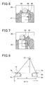
- FIG. 7 is a diagram conceptually illustrating significance of weight setting according to a difference in position in depth direction between a correction-target pixel and a weight-calculation-target pixel on an image coordinate;
- FIG. 8 is a diagram illustrating a relationship between a depth-direction position L and a disparity d;
- FIG. 9 is a diagram conceptually illustrating weight setting according to an inclination of an edge of a weight-calculation-target pixel.
- FIG. 10 is a diagram illustrating a relationship between an inclination of an edge and a disparity error e d .
- a disparity map generation system related to the present embodiment includes a right camera 1 , a left camera 2 , an arithmetic circuit 3 , and a memory 4 .
- the disparity map generation system implements the apparatus for generating a disparity map and a generation method therefor related to the present invention.
- the right camera 1 and the left camera 2 are arranged at mutually different positions and ensured to concurrently pick up an image of the same subject from mutually different viewpoints.
- the disparity map generation system is installed in a vehicle VE.
- the right and left cameras 1 and 2 may be mounted near the right and left ends, respectively, of the windshield of the vehicle VE, and the right and left cameras 1 and 2 may be both ensured to pick up images ahead of the vehicle.
- An object in which the disparity map generation system is installed is not construed to be limited to a vehicle, but may be any object that requires a disparity map, and thus may be devices or systems other than vehicles.
- the arithmetic circuit 3 (corresponding to an example of the disparity map generation apparatus) is an apparatus that acquires images picked up by the right camera 1 and the left camera 2 , and prepares a disparity map on the basis of the acquired images.
- the arithmetic circuit 3 is ensured to execute a program recorded in a ROM of a memory 4 (i.e., a non-transitory computer readable medium) to realize a process shown in FIG. 2 described later.
- the arithmetic circuit 3 uses a RAM of the memory 4 as a work area in which calculation results are temporarily stored.
- the arithmetic circuit 3 performs the process shown in FIG. 2 to function as an image acquirement section 31 , a disparity map generation section 32 , a weight determination section 33 , and a disparity map correction section 34 .
- the image acquirement section 31 acquires two images picked up from different viewpoints by the right camera 1 and the left camera 2 .
- the disparity map generation section 32 generates a disparity map that includes disparities each expressed in terms of the difference in pixel position between each of pixels and a corresponding one of pixels in the respective two images as acquired.
- the weight determination section 33 determines a weight as a degree of contribution to correction, for a correction-target pixel 41 (sequentially selected one by one) and surrounding pixels that are present in the vicinity of the correction-target pixel in a disparity map.
- the disparity map correction section 34 corrects the disparity of a correction-target pixel using a weighted average on the basis of the determined weight.
- the arithmetic circuit 3 acquires first, at step 105 , a right-camera image (corresponding to an example of the first image) picked up by the right camera 1 and a left-camera image (corresponding to an example of the second image) picked up by the left camera 2 , for storage in the RAM of the memory 4 .
- the arithmetic circuit 3 functions as the image acquisition section 31 .
- step 110 using the right-camera image and the left-camera image recorded on the RAM, known stereo matching is performed to generate a disparity map.
- the arithmetic circuit 3 functions as the disparity map generation section 32 .
- a disparity is calculated as a difference (divergence amount) between the positions of pixels in a lateral direction in the right-camera image and the left-camera image, the pixels being of the same subject included in both of the right-camera image and the left-camera image.
- the stereo matching used is a known block matching method.
- the arithmetic circuit 3 sets, in the right-camera image 21 , a mark block 23 (e.g., block of pixels arranged in 5 rows ⁇ 5 columns) that includes a mark pixel at the center. Then, the arithmetic circuit 3 searches through the left-camera image 22 for a block that includes the same subject as in the mark block 23 , and extracts the block that has been extracted as a result of the search, followed by correlating a center pixel of the drawn block with the mark pixel. A series of these processes are repeated while shifting the position for a mark pixel by raster scanning on a pixel-by-pixel basis until all the pixels in the right-camera image 21 have been searched as the mark pixels.
- a mark block 23 e.g., block of pixels arranged in 5 rows ⁇ 5 columns
- a plurality of comparison blocks 24 (each having the same shape and size as the mark block) as candidates are provided to a plurality of positions in the left-camera image 22 .
- the one with a minimum known SAD (Sum of Absolute Difference) (i.e. a comparison block having a highest correlation with the mark block 23 ) is selected as a block that includes the same subject as in the mark block 23 .
- SAD refers to a sum of absolute values of luminance differences, each of which is a difference in luminance between each of pixels and a corresponding one of pixels in the respective two blocks (the mark block and the comparison block).
- the plurality of comparison blocks 24 are selected from among only those blocks which each have a center pixel whose vertical level in the image coordinate (corresponding to a vertical level in FIG. 3 ) in the left-camera image 22 coincides with the vertical level of the mark pixel in the right-camera image.
- the block that includes the same subject as in the mark block 23 is searched in a horizontal direction as indicated by an arrow 25 . Accordingly, the pixel corresponding to the mark pixel is also searched in a horizontal direction at the same vertical level as the mark pixel.
- a corresponding one of the pixels in the left-camera image 22 is determined. Based on this, for each of the pixels in the right-camera image 21 , a disparity relative to a corresponding one of the pixels in the left-camera image 22 (difference between image coordinate positions in a lateral direction) is calculated. The calculated disparity is recorded on the RAM of the memory 4 , as a disparity corresponding to a pixel in the right-camera image 21 .
- disparity data are recorded being correlated to the individual pixels in the right-camera image 21 , and the data serve as a disparity map.
- the disparity map corresponds to data in which the disparities of the subject captured in the pixels of the right-camera image 21 are correlated to the coordinates of the respective pixels in the image.
- processings of steps 115 to 150 are repeated by the number of times equal to the number of pixels of the disparity map.
- a correction-target pixel and a plurality of surrounding pixels are newly set for the cycle.
- a block area 40 is set, which is composed of 9-row ⁇ 9-column dots centering on a correction-target pixel 41 .
- the plurality of surrounding pixels correspond to the pixels that have remained after removal of the correction-target pixel 41 from all the pixels in the block area 40 . It should be noted that the size and shape of the block area 40 may be appropriately changed.
- various weights are set for the correction-target pixel 41 and each of the surrounding pixels.
- the set weights are each used as an amount indicating a degree of contribution to correction in correcting the disparity of the correction-target pixel 41 using a weighted average at step 145 described later.
- a first weight Wx is set for the correction-target pixel 41 and each of the surrounding pixels.
- the weight W X is set according to a distance, on the image coordinate, from a pixel targeted to calculation of a weight (the correction-target pixel 41 or the surrounding pixel; hereinafter referred to as “weight-calculation-target pixel”) to the correction-target pixel 41 .
- weight-calculation-target pixel the correction-target pixel 41 or the surrounding pixel
- weight setting is expressed by:
- a second weight W I is set for the correction-target pixel 41 and each of the surrounding pixels.
- the weight W I is set according to a difference in a luminance value between a weight-calculation-target pixel and the correction-target pixel 41 (difference between luminance values in the right-camera image 21 ).
- the correction-target pixel 41 includes a part of a human body as a subject.
- the luminance of an area 43 containing a human body is obviously different from the luminance in an area 44 containing the background.
- the disparity of the background that is not so relevant to the disparity of the correction-target pixel 41 is permitted to have a low degree of contribution in performing disparity correction calculation for the correction-target pixel 41 .
- a third weight W Z is set for the correction-target pixel 41 and each of the surrounding pixels.
- the weight W Z is set according to a difference in position in a depth direction, between a weight-calculation-target pixel and the correction-target pixel 41 when converted to a three-dimensional coordinate.
- the correction-target pixel 41 includes a part of a human body as a subject.
- the block area 40 may include a subject 45 (e.g., white line on a road surface) which has a luminance close to that of the human body, but of which the distances from the cameras 1 and 2 thereto are greatly different from each other.
- the disparity of the subject 45 that is not so relevant to the disparity of the correction-target pixel 41 is permitted to have a low degree of contribution in performing disparity correction calculation for the correction-target pixel 41 .
- the position of a pixel in a depth direction when converted to a three-dimensional coordinate depends on the disparity of the pixel (the disparity calculated at immediately preceding step 110 ).
- b represents a distance between optical axes 1 a and 1 b of the two cameras 1 and 2 , respectively
- f represents a lens focal length that corresponds to a distance from a lens 1 b of the camera 1 to an image-formed surface 1 c (the distance is equal to the distance from a lens 2 b of the camera 2 to an image-formed surface 2 c )
- d represents a disparity.
- the focal length f and the distance b are datums.
- the difference in disparity between the two pixels also becomes large. Therefore, as the difference between the disparity of the correction-target pixel 41 and the disparity of a weight-calculation-target pixel becomes larger, the weight W Z of the weight-calculation-target pixel becomes lighter.
- a fourth weight W ⁇ is set for the correction-target pixel 41 and each of the surrounding pixels.
- the weight W ⁇ is set according to an inclination of an edge that is present in a weight-calculation-target pixel (edge in the right-camera image 21 ). Specifically, as a pixel has an edge whose inclination is more approximate to a horizontal level, the W ⁇ is permitted to be lighter. Accordingly, as shown in FIG. 9 , the pixel at a position of an edge 46 has a weight lighter than the weight of the pixel at a position of an edge 47 .
- the reason why the fourth weight W ⁇ is calculated in this way is that a weight-calculation-target pixel with an edge more approximate to a horizontal level tends to cause a larger error in the disparity calculation based on stereo matching at step 110 , and that the degree of contribution of such a weight-calculation-target pixel is desired to be lowered in the disparity correction calculation for the correction-target pixel 41 .
- two pixels that have taken the same subject in the respective right- and left-camera images are positionally offset in a horizontal direction, but are ensured not to be positionally offset in a vertical direction by adjusting in advance the positions and the orientations of the cameras 1 and 2 .
- the arithmetic circuit 3 carries out calibration using the right- and left-camera images in setting up the cameras 1 and 2 .
- the arithmetic circuit 3 determines correction parameters for the right- and left-camera images so as to eliminate the offset detected through the calibration. Thereafter, at step 105 of every cycle, the arithmetic circuit 3 applies correction, using the correction parameters, to the latest right- and left-camera images.
- a pixel 61 in which a subject is taken in the right-camera image, and a pixel 62 in which the same subject is taken in the left-camera image are not necessarily on the same horizontal line 61 (i.e. vertically offset).
- the pixel 61 is on an edge 61 in the right-camera image
- the pixel 62 is on an edge 62 (which is equal to the edge 61 for the subject) in the left-camera image.
- a pixel corresponding to the mark pixel is horizontally searched at the same vertical level as the mark pixel, as described above. Accordingly, the pixel 62 truly corresponding to the pixel 61 will never be correlated in fact to the pixel 61 .
- the pixel actually correlated, in the left-camera image, to the pixel 61 has a high probability of being a pixel 66 located at a position where the horizontal line 63 intersects the edge 65 passing through the pixel 62 , due to the nature of the block matching.
- the disparity calculated for the pixel 61 unavoidably includes a disparity error e d .
- the pixels whose edges have not been detected in the right-camera image 21 are permitted to have the weight W ⁇ of a zero value (zero degree of contribution). This is because the pixels whose edges have not been detected have a high tendency of causing an error in the disparity calculation based on stereo matching, compared to the pixels whose edges have been detected.
- the edge detection in the right-camera image 21 may be performed using a known method, such as a method of using a Sobel Filter. Further, the timing of performing the edge detection may be the point of acquiring the right-camera image 21 at step 105 . Alternatively, the edge detection may be conducted of the block area 40 at the point of starting step 135 .
- the final weight W 0 is necessarily zero if any one of the weights W X , W I , W Z and W ⁇ is zero. Accordingly, when the fourth weight W ⁇ is concerned, the weight W 0 will be zero for an edge whose edge has not been detected.
- the arithmetic circuit 3 performs steps 115 to 140 described above to function as the weight determination section ( 33 ).
- the disparity of the correction-target pixel 41 of this cycle is corrected using weighted average that uses the weight W 0 integrated at step 140 .
- the arithmetic circuit 3 performs step 145 to function as the disparity map correction section.
- f xy is calculated as follows:
- the double ⁇ in the mathematical expression means that a sum is calculated for all of the weight-calculation-target pixels in the block area 40 of this cycle. Accordingly, when the block area 40 is an area of 9-row ⁇ 9-column pixels, R is equivalent to an amount representing four pixels.
- step 150 it is determined whether or not all the pixels to be targeted (all the pixels in the right-camera image 21 ) have been targeted as correction-target pixels. If the determination is no, control returns to step 115 . If the determination is yes, the disparity map after correction is recorded on the RAM of the memory 4 , and then the process shown in FIG. 2 is terminated.
- steps 115 to 150 is executed by the number of times equal to the number of pixels of the right-camera image 21 , for the correction of the disparity of each of the pixels.
- the disparity map obtained as a result of such a correction may be used in any application.
- a distance from the own vehicle to an obstacle may be ensured to be detected on the basis of the disparity map.
- the image acquisition section 31 , the disparity map generation section 32 , the weight determination section 33 , and the disparity map generation section 32 of the arithmetic circuit 3 respectively correspond to the image acquiring means, the disparity map generating means, the weight determining means, and the disparity map generating means.
- the final weight does not have to be necessarily obtained in this way.
- any one of the weights W X , W I , W Z and W ⁇ may be used as a finally used weight, or any two of the weights W X , W I , W Z and W ⁇ may be selected and multiplied with each other for use as a final weight.
- each of the pixels of the right-camera image 21 is correlated with the disparity of a corresponding one of the pixels.
- each of the pixels of the left-camera image 22 may be correlated with the disparity of a corresponding one of the pixels.
- an image from an intermediate viewpoint may be virtually produced on the basis of the difference in the disparity between the right- and left-camera images 21 and 22 , and each of the pixels in the virtually produced image may be correlated with the disparity of a corresponding one of the pixels.
- the individual functions are realized by having the arithmetic circuit 3 executed the program.
- these functions may be ensured to be realized by means of hardware having these functions (e.g., FPGA that can program the circuit configuration).
Landscapes
- Engineering & Computer Science (AREA)
- Physics & Mathematics (AREA)
- General Physics & Mathematics (AREA)
- Theoretical Computer Science (AREA)
- Computer Vision & Pattern Recognition (AREA)
- Image Processing (AREA)
- Image Analysis (AREA)
- Testing, Inspecting, Measuring Of Stereoscopic Televisions And Televisions (AREA)
Applications Claiming Priority (3)
| Application Number | Priority Date | Filing Date | Title |
|---|---|---|---|
| JP2012181587A JP5949314B2 (ja) | 2012-08-20 | 2012-08-20 | 視差マップ生成装置および視差マップ生成装置用のプログラム |
| JP2012-181587 | 2012-08-20 | ||
| PCT/JP2013/072156 WO2014030630A1 (ja) | 2012-08-20 | 2013-08-20 | 視差マップを生成する装置及びその方法 |
Publications (2)
| Publication Number | Publication Date |
|---|---|
| US20150228057A1 US20150228057A1 (en) | 2015-08-13 |
| US9361668B2 true US9361668B2 (en) | 2016-06-07 |
Family
ID=50149939
Family Applications (1)
| Application Number | Title | Priority Date | Filing Date |
|---|---|---|---|
| US14/422,502 Active US9361668B2 (en) | 2012-08-20 | 2013-08-20 | Method and apparatus for generating disparity map |
Country Status (4)
| Country | Link |
|---|---|
| US (1) | US9361668B2 (ja) |
| JP (1) | JP5949314B2 (ja) |
| DE (1) | DE112013004103B4 (ja) |
| WO (1) | WO2014030630A1 (ja) |
Cited By (3)
| Publication number | Priority date | Publication date | Assignee | Title |
|---|---|---|---|---|
| US20150062308A1 (en) * | 2012-06-22 | 2015-03-05 | Nikon Corporation | Image processing apparatus, image-capturing apparatus and image processing method |
| EP3561450A4 (en) * | 2016-12-26 | 2020-07-29 | Hitachi Automotive Systems, Ltd. | STEREOCAMERA |
| US10902556B2 (en) | 2018-07-16 | 2021-01-26 | Nvidia Corporation | Compensating for disparity variation when viewing captured multi video image streams |
Families Citing this family (10)
| Publication number | Priority date | Publication date | Assignee | Title |
|---|---|---|---|---|
| US9058657B2 (en) * | 2011-04-28 | 2015-06-16 | Technologies Holdings Corp. | System and method for filtering data captured by a 3D camera |
| US20150346115A1 (en) * | 2014-05-30 | 2015-12-03 | Eric J. Seibel | 3d optical metrology of internal surfaces |
| JP6377970B2 (ja) * | 2014-06-12 | 2018-08-22 | トヨタ自動車株式会社 | 視差画像生成装置及び視差画像生成方法 |
| CN105120255B (zh) * | 2015-09-15 | 2018-11-20 | Tcl集团股份有限公司 | 一种视差图的平滑方法、装置及电子设备 |
| US10554947B1 (en) * | 2015-12-16 | 2020-02-04 | Marvell International Ltd. | Method and apparatus for stereo vision matching including disparity refinement based on matching merit values |
| CN108254738A (zh) * | 2018-01-31 | 2018-07-06 | 沈阳上博智像科技有限公司 | 避障告警方法、装置及存储介质 |
| EP3769038A1 (en) | 2018-03-19 | 2021-01-27 | Ricoh Company, Ltd. | Information processing apparatus, image capture apparatus, image processing system, and method of processing information |
| EP3706070A1 (en) | 2019-03-05 | 2020-09-09 | Koninklijke Philips N.V. | Processing of depth maps for images |
| WO2022018857A1 (ja) * | 2020-07-22 | 2022-01-27 | 日本電信電話株式会社 | デプスマップの精度向上装置、方法、およびプログラム |
| CN112767293B (zh) * | 2021-01-11 | 2023-04-11 | 达闼机器人股份有限公司 | 获取视差图像的方法、电子设备及存储介质 |
Citations (12)
| Publication number | Priority date | Publication date | Assignee | Title |
|---|---|---|---|---|
| JPH0927969A (ja) | 1995-05-08 | 1997-01-28 | Matsushita Electric Ind Co Ltd | 複数画像の中間像生成方法及び視差推定方法および装置 |
| JP2001351200A (ja) | 2000-06-09 | 2001-12-21 | Nissan Motor Co Ltd | 車載用物体検知装置 |
| US20020048395A1 (en) * | 2000-08-09 | 2002-04-25 | Harman Philip Victor | Image conversion and encoding techniques |
| JP2003209858A (ja) | 2002-01-17 | 2003-07-25 | Canon Inc | 立体画像生成方法及び記録媒体 |
| US20050232509A1 (en) * | 2004-04-16 | 2005-10-20 | Andrew Blake | Virtual image artifact detection |
| US20050232510A1 (en) * | 2004-04-16 | 2005-10-20 | Andrew Blake | Virtual image generation |
| US20050286756A1 (en) * | 2004-06-25 | 2005-12-29 | Stmicroelectronics, Inc. | Segment based image matching method and system |
| WO2011033673A1 (ja) | 2009-09-18 | 2011-03-24 | 株式会社 東芝 | 画像処理装置 |
| JP2011124935A (ja) | 2009-12-14 | 2011-06-23 | Sony Corp | 画像処理装置、および画像処理方法、並びにプログラム |
| US20110234765A1 (en) | 2010-03-24 | 2011-09-29 | Fujifilm Corporation | Image processing apparatus, image processing method, image processing program, and compound eye digital camera |
| JP2013164351A (ja) | 2012-02-10 | 2013-08-22 | Toyota Motor Corp | ステレオ視差算出装置 |
| US20140009462A1 (en) * | 2012-04-17 | 2014-01-09 | 3Dmedia Corporation | Systems and methods for improving overall quality of three-dimensional content by altering parallax budget or compensating for moving objects |
Family Cites Families (3)
| Publication number | Priority date | Publication date | Assignee | Title |
|---|---|---|---|---|
| JPH10289315A (ja) * | 1997-04-16 | 1998-10-27 | Sony Corp | 視差算出装置、距離算出装置およびこれらの方法 |
| GB9823689D0 (en) | 1998-10-30 | 1998-12-23 | Greenagate Limited | Improved methods and apparatus for 3-D imaging |
| JP4875762B2 (ja) * | 2010-05-26 | 2012-02-15 | シャープ株式会社 | 画像処理装置、画像表示装置および画像撮像装置 |
-
2012
- 2012-08-20 JP JP2012181587A patent/JP5949314B2/ja active Active
-
2013
- 2013-08-20 DE DE112013004103.0T patent/DE112013004103B4/de active Active
- 2013-08-20 WO PCT/JP2013/072156 patent/WO2014030630A1/ja active Application Filing
- 2013-08-20 US US14/422,502 patent/US9361668B2/en active Active
Patent Citations (15)
| Publication number | Priority date | Publication date | Assignee | Title |
|---|---|---|---|---|
| JPH0927969A (ja) | 1995-05-08 | 1997-01-28 | Matsushita Electric Ind Co Ltd | 複数画像の中間像生成方法及び視差推定方法および装置 |
| JP2001351200A (ja) | 2000-06-09 | 2001-12-21 | Nissan Motor Co Ltd | 車載用物体検知装置 |
| US20020048395A1 (en) * | 2000-08-09 | 2002-04-25 | Harman Philip Victor | Image conversion and encoding techniques |
| JP2003209858A (ja) | 2002-01-17 | 2003-07-25 | Canon Inc | 立体画像生成方法及び記録媒体 |
| US20050232509A1 (en) * | 2004-04-16 | 2005-10-20 | Andrew Blake | Virtual image artifact detection |
| US20050232510A1 (en) * | 2004-04-16 | 2005-10-20 | Andrew Blake | Virtual image generation |
| US20050286756A1 (en) * | 2004-06-25 | 2005-12-29 | Stmicroelectronics, Inc. | Segment based image matching method and system |
| WO2011033673A1 (ja) | 2009-09-18 | 2011-03-24 | 株式会社 東芝 | 画像処理装置 |
| US20120069009A1 (en) | 2009-09-18 | 2012-03-22 | Kabushiki Kaisha Toshiba | Image processing apparatus |
| JP2011124935A (ja) | 2009-12-14 | 2011-06-23 | Sony Corp | 画像処理装置、および画像処理方法、並びにプログラム |
| US20110273531A1 (en) | 2009-12-14 | 2011-11-10 | Atsushi Ito | Image processing apparatus, image processing method and program |
| US20110234765A1 (en) | 2010-03-24 | 2011-09-29 | Fujifilm Corporation | Image processing apparatus, image processing method, image processing program, and compound eye digital camera |
| JP2011203811A (ja) | 2010-03-24 | 2011-10-13 | Fujifilm Corp | 画像処理装置、画像処理方法、画像処理プログラム、及び複眼デジタルカメラ |
| JP2013164351A (ja) | 2012-02-10 | 2013-08-22 | Toyota Motor Corp | ステレオ視差算出装置 |
| US20140009462A1 (en) * | 2012-04-17 | 2014-01-09 | 3Dmedia Corporation | Systems and methods for improving overall quality of three-dimensional content by altering parallax budget or compensating for moving objects |
Non-Patent Citations (7)
| Title |
|---|
| "Depth Map Post-Filtering for Depth Image Based Rendering" by Norishige Fukushima et al., D vol. J94-D, No. 12, pp. 1992-1995, Journal of Institute of Electronics, Information and Communication Engineers with spot translation. |
| "Depth Map Refinement with Weighted Joint Bilateral Filter" by Takuya Matsumoto et al., 74th annual conference of Information Processing Society of Japan with spot translation. |
| International Preliminary Report on Patentability (in Japanese with English Translation) for PCT/JP2013/072156, issued Feb. 24, 2015. |
| International Search Report (in Japanese with English Translation) for PCT/JP2013/072156, mailed Oct. 8, 2013. |
| N. Fukushima et al., "Post filtering for depth image, for depth image based rendering," Journal of Institute of Electronics, Information and Communication Engineers, pp. 1992-1995, J94-D vol., Dec. 1, 2011. |
| Office Action dated Feb. 2, 2016 issued in the corresponding JP application No. 2012-181587 in Japanese with English translation. |
| T. Matsuo et al., "Weighed joint bilateral filter for improving depth estimation accuracy," 74th National Convention of Information Processing Societies, Collection of preliminary manuscripts 2012-10004-116. |
Cited By (4)
| Publication number | Priority date | Publication date | Assignee | Title |
|---|---|---|---|---|
| US20150062308A1 (en) * | 2012-06-22 | 2015-03-05 | Nikon Corporation | Image processing apparatus, image-capturing apparatus and image processing method |
| US9723288B2 (en) * | 2012-06-22 | 2017-08-01 | Nikon Corporation | Image processing apparatus, image-capturing apparatus and image processing method |
| EP3561450A4 (en) * | 2016-12-26 | 2020-07-29 | Hitachi Automotive Systems, Ltd. | STEREOCAMERA |
| US10902556B2 (en) | 2018-07-16 | 2021-01-26 | Nvidia Corporation | Compensating for disparity variation when viewing captured multi video image streams |
Also Published As
| Publication number | Publication date |
|---|---|
| WO2014030630A1 (ja) | 2014-02-27 |
| JP2014038546A (ja) | 2014-02-27 |
| US20150228057A1 (en) | 2015-08-13 |
| DE112013004103T5 (de) | 2015-05-28 |
| JP5949314B2 (ja) | 2016-07-06 |
| DE112013004103B4 (de) | 2018-09-13 |
Similar Documents
| Publication | Publication Date | Title |
|---|---|---|
| US9361668B2 (en) | Method and apparatus for generating disparity map | |
| US8548226B2 (en) | Stereo image processing device and method | |
| CN108076338B (zh) | 图像视觉处理方法、装置及设备 | |
| US8655081B2 (en) | Lane recognition system, lane recognition method, and lane recognition program | |
| WO2012120856A1 (ja) | 物体検出装置及び物体検出方法 | |
| EP3082066A1 (en) | Road surface gradient detection device | |
| EP2767927A2 (en) | Face information detection apparatus, vehicle device control system employing face information detection apparatus, and carrier medium of face information detection program | |
| US20130148855A1 (en) | Positioning information forming device, detection device, and positioning information forming method | |
| CN105335955A (zh) | 对象检测方法和对象检测装置 | |
| CN105069804B (zh) | 基于智能手机的三维模型扫描重建方法 | |
| US20150367781A1 (en) | Lane boundary estimation device and lane boundary estimation method | |
| JP2009176090A (ja) | 環境認識装置 | |
| JP6377970B2 (ja) | 視差画像生成装置及び視差画像生成方法 | |
| JP2011128756A (ja) | 物体検出装置 | |
| JP2018105682A (ja) | ステレオカメラ | |
| US20210387636A1 (en) | Method for estimating distance to and location of autonomous vehicle by using mono camera | |
| US8675047B2 (en) | Detection device of planar area and stereo camera system | |
| WO2014054124A1 (ja) | 路面標示検出装置及び路面標示検出方法 | |
| CN111260538B (zh) | 基于长基线双目鱼眼相机的定位及车载终端 | |
| EP3896387B1 (en) | Image processing device | |
| EP3330893A1 (en) | Information processing device, information processing method, and carrier means | |
| CN112513573A (zh) | 立体摄像机装置 | |
| JP2016111585A (ja) | 画像処理装置、システム、画像処理方法、およびプログラム | |
| JPH10124687A (ja) | 道路白線検出方法及び道路白線検出装置 | |
| WO2023068034A1 (ja) | 画像処理装置 |
Legal Events
| Date | Code | Title | Description |
|---|---|---|---|
| AS | Assignment |
Owner name: NIPPON SOKEN, INC., JAPAN Free format text: ASSIGNMENT OF ASSIGNORS INTEREST;ASSIGNORS:ISHIGAMI, HIROTAKE;SHIRAI, NORIAKI;IMANISHI, MASAYUKI;AND OTHERS;SIGNING DATES FROM 20150402 TO 20150413;REEL/FRAME:036709/0900 Owner name: TOYOTA JIDOSHA KABUSHIKI KAISHA, JAPAN Free format text: ASSIGNMENT OF ASSIGNORS INTEREST;ASSIGNORS:ISHIGAMI, HIROTAKE;SHIRAI, NORIAKI;IMANISHI, MASAYUKI;AND OTHERS;SIGNING DATES FROM 20150402 TO 20150413;REEL/FRAME:036709/0900 Owner name: DENSO CORPORATION, JAPAN Free format text: ASSIGNMENT OF ASSIGNORS INTEREST;ASSIGNORS:ISHIGAMI, HIROTAKE;SHIRAI, NORIAKI;IMANISHI, MASAYUKI;AND OTHERS;SIGNING DATES FROM 20150402 TO 20150413;REEL/FRAME:036709/0900 |
|
| FEPP | Fee payment procedure |
Free format text: PAYOR NUMBER ASSIGNED (ORIGINAL EVENT CODE: ASPN); ENTITY STATUS OF PATENT OWNER: LARGE ENTITY |
|
| STCF | Information on status: patent grant |
Free format text: PATENTED CASE |
|
| MAFP | Maintenance fee payment |
Free format text: PAYMENT OF MAINTENANCE FEE, 4TH YEAR, LARGE ENTITY (ORIGINAL EVENT CODE: M1551); ENTITY STATUS OF PATENT OWNER: LARGE ENTITY Year of fee payment: 4 |
|
| MAFP | Maintenance fee payment |
Free format text: PAYMENT OF MAINTENANCE FEE, 8TH YEAR, LARGE ENTITY (ORIGINAL EVENT CODE: M1552); ENTITY STATUS OF PATENT OWNER: LARGE ENTITY Year of fee payment: 8 |