US936076A - Pump. - Google Patents
Pump. Download PDFInfo
- Publication number
- US936076A US936076A US46932108A US1908469321A US936076A US 936076 A US936076 A US 936076A US 46932108 A US46932108 A US 46932108A US 1908469321 A US1908469321 A US 1908469321A US 936076 A US936076 A US 936076A
- Authority
- US
- United States
- Prior art keywords
- pump
- piston
- valves
- tubular
- pistons
- Prior art date
- Legal status (The legal status is an assumption and is not a legal conclusion. Google has not performed a legal analysis and makes no representation as to the accuracy of the status listed.)
- Expired - Lifetime
Links
- XLYOFNOQVPJJNP-UHFFFAOYSA-N water Substances O XLYOFNOQVPJJNP-UHFFFAOYSA-N 0.000 description 5
- 230000005484 gravity Effects 0.000 description 3
- 238000005086 pumping Methods 0.000 description 2
- 210000001217 buttock Anatomy 0.000 description 1
- 230000006835 compression Effects 0.000 description 1
- 238000007906 compression Methods 0.000 description 1
- 238000010276 construction Methods 0.000 description 1
- 230000007547 defect Effects 0.000 description 1
- 210000004907 gland Anatomy 0.000 description 1
- 238000005192 partition Methods 0.000 description 1
- 238000009877 rendering Methods 0.000 description 1
Images
Classifications
-
- F—MECHANICAL ENGINEERING; LIGHTING; HEATING; WEAPONS; BLASTING
- F04—POSITIVE - DISPLACEMENT MACHINES FOR LIQUIDS; PUMPS FOR LIQUIDS OR ELASTIC FLUIDS
- F04B—POSITIVE-DISPLACEMENT MACHINES FOR LIQUIDS; PUMPS
- F04B47/00—Pumps or pumping installations specially adapted for raising fluids from great depths, e.g. well pumps
Definitions
- ALEXANDER BAIRD SR., OEGREENSBURG, PENNSYLVANIA, ssIeNoR or oNE-IIALF i T'o ALEXANDER EAIRD, J'Ri, oF
- My gravity -flap valves are particularlydesigned for that type of reciprocatorypump -Wherein tubular pistons are employed for 'pumping' water, this type of pump being common to Water Works and similar pumping stations.
- vMy invention aims to obviate the above defects by providing a gravity flap valve with which sticks and such foreign matter cannot interfere or prevent the valves from operating.
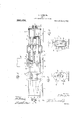
- Fig. 1 is a side elevation of a. pump partly in ⁇ section equipped with my improved valve
- Fig. 2 is an ,end view ot the same
- Fig. 3 is a cross sectional vic ⁇ r taken on the linev X-X of Fig. 1.
- 1 desig-- nates bed plates supporting a cylinder, which comprises integral end sections 2 and 8 and an intermediate section 4, said sections being coupled togetherby yokes 5.
- yThe sections 2, 3'a ⁇ nd4 of the cylinder are oval in cross section with vertical ends of the cylinders 2 and 3 are.
- closed b v detachable heads 5 having a stufling box 6l for piston rods 7, said rods beingreciprocated by the usual well known type of steam Y are provided with openings S and glands l), and extending through said openings and glandsare tubular pistons i Specification of Letters Patent. f Application filed December 26, 1908.
- iap valves 14 Pivotally connected to the heads 13 at 5 thc ends of the tubular piston 10 are iap valves 14 having Weights or knobs 15 which normally maintain said valves in ajclosed position closing the ends of the tubular piston 10.
- This piston -intermediate the ends plurality of longitudinally disposed inlet ports 16, and separating, said piston from the pistons 11 and 12, Within the intermediate section 4, is a parti-v tion 1'7, wherebywater admitted to the section 4 through the inlet opening 18 thereof will pass directly .into the tubular piston 10.
- the confronting ends. of the tubular istons 11 and 12 are provided with flap valjves 19 and 20, similar to the flap'valve 14, ⁇ and the section 4 above the partition 17 has a water outlet opening 21.
- This opening can conii municate With a reservoir 22 arranged above the pump or With any suitable tank (not shown). Water admitted through the opening 18 passes through the tubular piston 10,
- a cylinder cpm prising end y sections and connecting the sections ⁇ said intermediate sectioi'i being provided with an inlet and an outlet compartment ⁇ a hollow piston havini; its end disposed in the end sections extending through the inlet compartment ⁇ ,said l' pump 109 an intermedi'atesectioi'i, yokes 10.5
- piston being provided' with longitudinally extending perpherally spaced inlet ports
- flap valves controlling Athe outer ends of the inlet piston, hollow 'discharge pistons'disposed parallel of the inlet plston operating in the cylinder, means connecting;l the adjacent ends of the inlet piston and the discharge piston, and weighted flap valves con-
Landscapes
- Engineering & Computer Science (AREA)
- Mechanical Engineering (AREA)
- General Engineering & Computer Science (AREA)
- Details Of Reciprocating Pumps (AREA)
Description
A. BAIRD, SB.
PUMP.
APPLICATION FILED DBO. 26,
Patented Get. 5, 1909.
ALEXANDER BAIRD, SR., OEGREENSBURG, PENNSYLVANIA, ssIeNoR or oNE-IIALF i T'o ALEXANDER EAIRD, J'Ri, oF
GREENSBURG, PENNSYLVANIA.
PUMP.
To all whom/it may concern:
ABe vit known that I, ALEXANDER BAIRD, Sr., a citizen of the United States of America', residing at Greensburg, Westmorelandv and State of Pennsylvania, have invented certain new and useful lmprovements in Pumps, of which the following is a specification, reference being had therein tothe accompanying drawing.
,')lhis invention relates to pumps, and the object of my invention is to provide novel gravity ii'apvalves which Will insu-re a positive operation of the pump..
My gravity -flap valves are particularlydesigned for that type of reciprocatorypump -Wherein tubular pistons are employed for 'pumping' water, this type of pump being common to Water Works and similar pumping stations.
It has been the practice heretofore to use spring-pressed valves in connection with the above type of pninpand by reasonof sticks and such foreign matter entering the pump,
the operation of the spring-'pressed valves has becn'retarded, rendering the pump ineffective for the pui'pose'for' which it is intended. j
vMy invention aims to obviate the above defects by providing a gravity flap valve with which sticks and such foreign matter cannot interfere or prevent the valves from operating. Y
The detail construction entering into my l invention will be hereinafter described and then specifically claimed.
Referring` to the drawings :hlfigure 1 is a side elevation of a. pump partly in `section equipped with my improved valve, Fig. 2 is an ,end view ot the same, and Fig. 3 is a cross sectional vic\r taken on the linev X-X of Fig. 1.
In the.accompanying drawings, 1 desig-- nates bed plates supporting a cylinder, which comprises integral end sections 2 and 8 and an intermediate section 4, said sections being coupled togetherby yokes 5. yThe sections 2, 3'a`nd4 of the cylinder are oval in cross section with vertical ends of the cylinders 2 and 3 are. closed b v detachable heads 5 having a stufling box 6l for piston rods 7, said rods beingreciprocated by the usual well known type of steam Y are provided with openings S and glands l), and extending through said openings and glandsare tubular pistons i Specification of Letters Patent. f Application filed December 26, 1908. Serial No. 469,321
in the county ofi thereof is provided with a flat sides, and the outer Patented Oct. 5, 1909.
11 and 12 arranged above the tubular piston 10 with the combined length of the't- nbnlaru pistons 11 and 12 approximately that of the tubulaipiston 10. The outer ends ofthe tubular pist-ons lOrto in piston heads 1 3 the piston rods 7,
which are connected to said heads being adapted 12 inclusive are mounted 5 t-o freely move Within the end sections .2 and 3 of the pump.
Pivotally connected to the heads 13 at 5 thc ends of the tubular piston 10 are iap valves 14 having Weights or knobs 15 which normally maintain said valves in ajclosed position closing the ends of the tubular piston 10. This piston-intermediate the ends plurality of longitudinally disposed inlet ports 16, and separating, said piston from the pistons 11 and 12, Within the intermediate section 4, is a parti-v tion 1'7, wherebywater admitted to the section 4 through the inlet opening 18 thereof will pass directly .into the tubular piston 10. The confronting ends. of the tubular istons 11 and 12 are provided with flap valjves 19 and 20, similar to the flap'valve 14, `and the section 4 above the partition 17 has a water outlet opening 21. This opening can conii municate With a reservoir 22 arranged above the pump or With any suitable tank (not shown). Water admitted through the opening 18 passes through the tubular piston 10,
opens the valves 14 and enters thc sections 2 and 3 of the pump. Assuming that the tubular pistons are moving in the direction ofthe arrowv'A, Fig. 1, the water within the section 2 will be compressed and discharged through the tubular piston ll and the opening 2l, while iva'tcr 'is arcmnulating in the section 3 for compression by a return stroke of the tubular pistons l0 and ll.A
lt is apparent that il. will be impossible for sticks and foreign mallcr to prevent thc valves 14, 19 and 20 from closing, and consequently a positive operation of said valves is insured and the etlicicncy of the considerably increased.
Having now described my invention what l claim as new, is
' ln combination, a cylinder cpmprising end y sections and connecting the sections` said intermediate sectioi'i being provided with an inlet and an outlet compartment` a hollow piston havini; its end disposed in the end sections extending through the inlet compartment` ,said l' pump 109 an intermedi'atesectioi'i, yokes 10.5
piston being provided' with longitudinally extending perpherally spaced inlet ports,
flap valves controlling Athe outer ends of the inlet piston, hollow 'discharge pistons'disposed parallel of the inlet plston operating in the cylinder, means connecting;l the adjacent ends of the inlet piston and the discharge piston, and weighted flap valves con-
Priority Applications (1)
| Application Number | Priority Date | Filing Date | Title |
|---|---|---|---|
| US46932108A US936076A (en) | 1908-12-26 | 1908-12-26 | Pump. |
Applications Claiming Priority (1)
| Application Number | Priority Date | Filing Date | Title |
|---|---|---|---|
| US46932108A US936076A (en) | 1908-12-26 | 1908-12-26 | Pump. |
Publications (1)
| Publication Number | Publication Date |
|---|---|
| US936076A true US936076A (en) | 1909-10-05 |
Family
ID=3004498
Family Applications (1)
| Application Number | Title | Priority Date | Filing Date |
|---|---|---|---|
| US46932108A Expired - Lifetime US936076A (en) | 1908-12-26 | 1908-12-26 | Pump. |
Country Status (1)
| Country | Link |
|---|---|
| US (1) | US936076A (en) |
-
1908
- 1908-12-26 US US46932108A patent/US936076A/en not_active Expired - Lifetime
Similar Documents
| Publication | Publication Date | Title |
|---|---|---|
| US570528A (en) | Double-acting pump | |
| US746344A (en) | Interchangeable-cylinder pump. | |
| US160207A (en) | Improvement in force-pumps | |
| US941646A (en) | Air-compressor. | |
| US1185139A (en) | Valve mechanism for pumps, compressors, &c. | |
| US721661A (en) | Water-motor. | |
| US1656362A (en) | Double-acting steam and like pump | |
| US764156A (en) | Hydraulic-motor pump. | |
| US1046167A (en) | Pump. | |
| US731623A (en) | Pump. | |
| US547211A (en) | hawley | |
| US374400A (en) | Half to minna van normann and henry l | |
| US899720A (en) | Air and gas compressor. | |
| US508495A (en) | William c | |
| US529432A (en) | Force-pump | |
| US793380A (en) | Blowing-engine. | |
| US274154A (en) | Steam-pump | |
| US453925A (en) | berridg-e | |
| US599004A (en) | Forge-pump | |
| US954994A (en) | Pump. | |
| US268675A (en) | Double-acting pump | |
| US1182372A (en) | Air-compressing pump. | |
| US72820A (en) | Improvement in air-pumps | |
| US574251A (en) | David lippy | |
| US512776A (en) | Edward h |