US9360155B2 - Microphone mounting apparatus - Google Patents
Microphone mounting apparatus Download PDFInfo
- Publication number
- US9360155B2 US9360155B2 US13/748,188 US201313748188A US9360155B2 US 9360155 B2 US9360155 B2 US 9360155B2 US 201313748188 A US201313748188 A US 201313748188A US 9360155 B2 US9360155 B2 US 9360155B2
- Authority
- US
- United States
- Prior art keywords
- jaw
- microphone
- jaws
- pair
- clamp
- Prior art date
- Legal status (The legal status is an assumption and is not a legal conclusion. Google has not performed a legal analysis and makes no representation as to the accuracy of the status listed.)
- Active, expires
Links
- 230000000994 depressogenic effect Effects 0.000 claims abstract description 16
- 238000000034 method Methods 0.000 claims description 8
- 230000008878 coupling Effects 0.000 claims 3
- 238000010168 coupling process Methods 0.000 claims 3
- 238000005859 coupling reaction Methods 0.000 claims 3
- 230000009977 dual effect Effects 0.000 abstract description 6
- 238000009527 percussion Methods 0.000 description 14
- 238000007373 indentation Methods 0.000 description 9
- 244000261422 Lysimachia clethroides Species 0.000 description 7
- 230000000881 depressing effect Effects 0.000 description 3
- 230000008901 benefit Effects 0.000 description 2
- 238000004519 manufacturing process Methods 0.000 description 2
- 230000013011 mating Effects 0.000 description 2
- 239000002184 metal Substances 0.000 description 2
- 239000007769 metal material Substances 0.000 description 2
- 238000012986 modification Methods 0.000 description 2
- 230000004048 modification Effects 0.000 description 2
- 239000011295 pitch Substances 0.000 description 2
- 230000002787 reinforcement Effects 0.000 description 2
- 102220030421 rs398124134 Human genes 0.000 description 2
- 229910001369 Brass Inorganic materials 0.000 description 1
- 102220582150 Caspase recruitment domain-containing protein 16_A56D_mutation Human genes 0.000 description 1
- 241000333074 Eucalyptus occidentalis Species 0.000 description 1
- 240000000022 Silene vulgaris Species 0.000 description 1
- 235000011312 Silene vulgaris Nutrition 0.000 description 1
- 238000005452 bending Methods 0.000 description 1
- 239000010951 brass Substances 0.000 description 1
- 238000005266 casting Methods 0.000 description 1
- 238000003754 machining Methods 0.000 description 1
- 239000011435 rock Substances 0.000 description 1
- 102220224495 rs1060503668 Human genes 0.000 description 1
- 230000001755 vocal effect Effects 0.000 description 1
- 239000002023 wood Substances 0.000 description 1
Images


Classifications
-
- F—MECHANICAL ENGINEERING; LIGHTING; HEATING; WEAPONS; BLASTING
- F16—ENGINEERING ELEMENTS AND UNITS; GENERAL MEASURES FOR PRODUCING AND MAINTAINING EFFECTIVE FUNCTIONING OF MACHINES OR INSTALLATIONS; THERMAL INSULATION IN GENERAL
- F16M—FRAMES, CASINGS OR BEDS OF ENGINES, MACHINES OR APPARATUS, NOT SPECIFIC TO ENGINES, MACHINES OR APPARATUS PROVIDED FOR ELSEWHERE; STANDS; SUPPORTS
- F16M13/00—Other supports for positioning apparatus or articles; Means for steadying hand-held apparatus or articles
- F16M13/02—Other supports for positioning apparatus or articles; Means for steadying hand-held apparatus or articles for supporting on, or attaching to, an object, e.g. tree, gate, window-frame, cycle
-
- B—PERFORMING OPERATIONS; TRANSPORTING
- B23—MACHINE TOOLS; METAL-WORKING NOT OTHERWISE PROVIDED FOR
- B23P—METAL-WORKING NOT OTHERWISE PROVIDED FOR; COMBINED OPERATIONS; UNIVERSAL MACHINE TOOLS
- B23P11/00—Connecting or disconnecting metal parts or objects by metal-working techniques not otherwise provided for
-
- H—ELECTRICITY
- H04—ELECTRIC COMMUNICATION TECHNIQUE
- H04R—LOUDSPEAKERS, MICROPHONES, GRAMOPHONE PICK-UPS OR LIKE ACOUSTIC ELECTROMECHANICAL TRANSDUCERS; DEAF-AID SETS; PUBLIC ADDRESS SYSTEMS
- H04R1/00—Details of transducers, loudspeakers or microphones
- H04R1/08—Mouthpieces; Microphones; Attachments therefor
-
- F—MECHANICAL ENGINEERING; LIGHTING; HEATING; WEAPONS; BLASTING
- F16—ENGINEERING ELEMENTS AND UNITS; GENERAL MEASURES FOR PRODUCING AND MAINTAINING EFFECTIVE FUNCTIONING OF MACHINES OR INSTALLATIONS; THERMAL INSULATION IN GENERAL
- F16B—DEVICES FOR FASTENING OR SECURING CONSTRUCTIONAL ELEMENTS OR MACHINE PARTS TOGETHER, e.g. NAILS, BOLTS, CIRCLIPS, CLAMPS, CLIPS OR WEDGES; JOINTS OR JOINTING
- F16B2/00—Friction-grip releasable fastenings
- F16B2/02—Clamps, i.e. with gripping action effected by positive means other than the inherent resistance to deformation of the material of the fastening
- F16B2/06—Clamps, i.e. with gripping action effected by positive means other than the inherent resistance to deformation of the material of the fastening external, i.e. with contracting action
- F16B2/12—Clamps, i.e. with gripping action effected by positive means other than the inherent resistance to deformation of the material of the fastening external, i.e. with contracting action using sliding jaws
-
- Y—GENERAL TAGGING OF NEW TECHNOLOGICAL DEVELOPMENTS; GENERAL TAGGING OF CROSS-SECTIONAL TECHNOLOGIES SPANNING OVER SEVERAL SECTIONS OF THE IPC; TECHNICAL SUBJECTS COVERED BY FORMER USPC CROSS-REFERENCE ART COLLECTIONS [XRACs] AND DIGESTS
- Y10—TECHNICAL SUBJECTS COVERED BY FORMER USPC
- Y10T—TECHNICAL SUBJECTS COVERED BY FORMER US CLASSIFICATION
- Y10T29/00—Metal working
- Y10T29/49—Method of mechanical manufacture
- Y10T29/49826—Assembling or joining
- Y10T29/49947—Assembling or joining by applying separate fastener
- Y10T29/49959—Nonresilient fastener
Definitions
- the disclosure herein relates to the field of sound production, more specifically to the field of sound production using one or more microphones. Aspects of the disclosure relate to a mounting apparatus for a placement of a microphone in the proximity of a musical instrument or other audio source.
- Configuring microphones for a drum set is often a complex task of an audio or sound engineer in a recording studio or at a venue.
- an audio engineer often has to position microphones adjacent to a variety of other sound sources when recording or providing sound reinforcement for a musical performance.
- the engineer may have a need to “mic” a variety of different instruments and sound sources, including vocals, amplifiers, acoustic instruments, brass and woodwind instruments, etc. In doing so, the audio engineer often must arrange a variety of microphones adjacent or proximate to such sound sources.
- a microphone may be mounted to mounting apparatus in order to receive sound from a sound source, e.g., a musical instrument.
- the mounting apparatus may securely mount different microphones to a variety of musical instruments and other sound sources.
- the mounting apparatus may be used for drum and percussion applications.
- the mounting apparatus may be used to directly mount a microphone to drum rims, hand percussion, drum and percussion hardware, and microphone stands. While the mounting apparatus may be used with drums and percussion instruments, the mounting apparatus may also be applicable to amplifier cabinets, piano frames, and other mounting surfaces where microphones may be employed.
- the mounting apparatus incorporates a dual jaw design to allow for easy, fast, and secure mounting to a variety of clamping surfaces with a variety of geometries, including drum rims, hand percussion tension rods, percussion hardware, and microphone stands.
- the mounting apparatus supports a quick release adjustment for easy and fast engagement and disengagement of the dual jaws, consequently reducing time needed to securely clamp and remove the mounting apparatus with a clamping surface.
- a microphone clamp may accept a variety of microphone mounting accessories, thus providing compatibility with numerous types of microphones.
- a mounting apparatus includes a pair of jaws for attaching the mounting apparatus to a clamping surface and a jaw stud for adjusting the pair of jaws.
- the mounting apparatus may have a release mechanism that is coupled to the jaw stud, in which the release mechanism releases one of jaws when the release mechanism is depressed allowing the jaw to freely slide along the jaw stud to open or close the pair of jaws on the clamping surface. While the release mechanism is not depressed, the release mechanism engages the threaded portion of the jaw stud, thereby allowing the first pair of jaws to tighten on the clamping surface when the jaw stud is turned along the threaded portion in a first direction.
- the mounting apparatus includes a microphone clamp to hold a microphone mounting accessory or microphone.
- the mounting apparatus also includes a second pair of jaws for attaching the mounting apparatus to a clamping surface.
- the second pair may be oriented at a fixed angle (e.g., 90 degrees) with respect to the other pair of jaws.
- the release mechanism includes a dowel release having a hole through which the jaw stud is situated.
- the hole has two curved surfaces, where the second curved surface is threaded to engage along a threaded portion of the jaw stud and the first curved surface is smooth so as to permit the dowel release to move along the jaw stud.
- FIG. 1 shows a drum set for which microphones may be configured by a microphone mounting apparatus according to aspects of the disclosure.
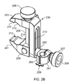
- FIGS. 2A-2B show a microphone mounting apparatus according to aspects of the disclosure.
- FIG. 3A-3B show top and bottom views of the microphone mounting apparatus in FIGS. 2A-2B according to aspects of the disclosure.
- FIGS. 4A-4B show side views of the microphone mounting apparatus in FIGS. 2A-2B according to aspects of the disclosure.
- FIGS. 5A-5B show an upper jaw frame of the microphone mounting apparatus in FIGS. 2A-2B according to aspects of the disclosure.
- FIGS. 6A-6C show a lower jaw of the microphone mounting apparatus in FIGS. 2A-2B according to aspects of the disclosure.
- FIG. 7 shows a jaw stud of the microphone mounting apparatus in FIGS. 2A-2B according to aspects of the disclosure.
- FIGS. 8A-8B show a jaw knob of the microphone mounting apparatus in FIGS. 2A-2B according to aspects of the disclosure.
- FIG. 9 shows a release dowel of the microphone mounting apparatus in FIGS. 2A-2B according to aspects of the disclosure.
- FIG. 10 shows a microphone clamp bolt of the microphone mounting apparatus in FIGS. 2A-2B according to aspects of the disclosure.
- FIGS. 11A-11B show a clamp knob of the microphone mounting apparatus in FIGS. 2A-2B according to aspects of the disclosure.
- FIGS. 12A-12B show a knob lid for the knob in FIGS. 11A-11B according to aspects of the disclosure.
- FIG. 13 shows a microphone mounting accessory that may be secured by the clamp of the microphone mounting in FIGS. 2A-2B according to aspects of the disclosure.
- FIG. 14 shows another microphone mounting accessory that may be secured by the clamp of the microphone mounting in FIGS. 2A-2B according to aspects of the disclosure.
- FIG. 15 shows yet another microphone mounting accessory that may be secured by the clamp of the microphone mounting in FIGS. 2A-2B according to aspects of the disclosure.
- FIG. 16 shows yet another microphone mounting accessory that may be secured by the clamp of the microphone mounting in FIGS. 2A-2B according to aspects of the disclosure.
- FIG. 17 shows yet another microphone mounting accessory that may be secured by the clamp of the microphone mounting in FIGS. 2A-2B according to aspects of the disclosure.
- a microphone may be mounted to a mounting apparatus in order to receive sound from a sound source, e.g., a musical instrument.
- the mounting apparatus may securely mount different microphones to a variety of musical instruments and other sound sources.
- the mounting apparatus may be used for drum and percussion applications.
- the mounting apparatus may be used to directly mount a microphone to drum rims, hand percussion, drum and/or percussion hardware, and microphone stands. While the mounting apparatus may be used with drums and percussion instruments, the mounting apparatus may be applicable to amplifier cabinets, piano frames, and other mounting surfaces where microphones may be employed.
- the mounting apparatus incorporates a dual jaw design to allow for easy, fast, and secure mounting to a variety of clamping surfaces with a variety of geometries, including drum rims, hand percussion tension rods, percussion hardware, and microphone stands.
- the mounting apparatus supports a quick release adjustment for easy and fast engagement and disengagement of the dual jaws, consequently reducing time needed to securely clamp and remove the mounting apparatus with a clamping surface.
- a microphone clamp may accept a variety of microphone mounting accessories, thus providing compatibility with numerous types of microphones.
- FIG. 1 shows drum set 100 that may be configured with microphone mounting apparatus 200 according to aspects of the disclosure.
- Drum set 100 (which may be referred to as a drum kit or trap set) comprises a collection of drums, cymbals and often other percussion instruments, such as cowbells, wood blocks, triangles, chimes, or tambourines, arranged for convenient playing by a single person (drummer).
- the individual instruments of a drum set are hit by a variety of implements held in the hand of the drummer, including sticks, brushes, and mallets.
- Two notable exceptions include the bass drum 101 , played by a foot-operated pedal, and the hi-hat cymbals 102 , which may be struck together using a foot pedal in addition to being played with sticks or brushes.
- the feet are usually occupied by bass drum 101 and hi hat cymbals 102 , and as a result the drummer often plays in a seated position.
- Drum set 100 comprises bass drum 101 , floor tom 103 , snare drum 104 , tom-toms 105 a , 105 b , and a variety of cymbals including hi-hat cymbals 102 , ride cymbal 106 and a crash cymbal (not explicitly shown) but may include additional percussion instruments.
- Drums such as floor tom 103 , tom-toms 105 a , 105 b , snare drum 104 , and bass drum 101 have one or more drum rings or rims which hold a drum head onto the body of the drum.
- Drum rims 107 - 111 often are metal bands having a circular shape and a generally elongated cross-section, and are usually located at the ends of the drums, near the top end of the drum where the drum head is located. In some embodiments, drum rims 107 - 111 have a generally rectangular cross-section. Drum rims 107 - 111 may be adjusted by various mechanical means to adjust the tone, tuning, and response of the drum head.
- drum kit's set-up Various music genres often incorporate the stylistically appropriate use of the drum kit's set-up. For example, in most forms of rock music, bass drum 104 , hi-hat cymbals 102 , and snare drum 104 are the primary instruments used to create a drum beat, whereas in jazz, ride cymbals 106 and snare drum 104 tend to be more prevalent.
- FIGS. 2A-2B show microphone mounting apparatus 200 according to aspects of the disclosure.
- FIG. 2A shows a front view of apparatus 200
- FIG. 2B shows an isometric view of apparatus 200 .
- Apparatus 200 may serve as a multipurpose drum clamp, although some embodiments may be applicable to other musical instruments.
- Some or all of the components of apparatus 200 may be formed by machining or casting techniques. With some embodiments, non-metallic materials may be used for some or all of the components.
- Mounting apparatus 200 may support a quick/fine clamping adjustment of lower jaw 201 and upper jaw 203 .
- Lower jaw 201 and upper jaw 203 typically clamp to a clamping surface on or near a musical instrument to secure microphone mounting apparatus 200 so that a microphone or microphone mounting accessory (not explicitly shown) may be secured by microphone clamp 206 .
- the quick/fine clamping adjustment permits the lower and upper jaws 201 , 203 to be first adjusted to close quickly on the clamping surface, and then further tightening on the clamping surface via the fine adjustment.
- the quick adjustment is accomplished by depressing release mechanism 209 on the lower jaw 201 , which releases release mechanism 209 and allows the lower jaw 201 to move upwards to quickly close the lower and upper jaws on its intended clamping surface.
- release mechanism 209 may be released, and knob 205 in conjunction with screw 204 (corresponding to jaw stud 704 as shown in FIG. 7 ) may be tightened to cause lower jaw 201 and/or upper jaw 203 to grip down tighter on the clamping surface.
- release mechanism 209 further allows quick release of the jaws 201 , 203 by depressing release mechanism 209 and separating the jaws 201 , 203 from one another.
- a microphone or microphone mounting accessory may be mounted on to mounting apparatus 200 . Consequently, the mounting apparatus 200 provides the ability to quickly clamp, tighten, and set up a microphone (e.g., on a drum kit 100 as shown in FIG. 1 ) as well as the ability to quickly release and remove mounting apparatus 200 .
- apparatus 200 may support two pairs of jaws. As shown in FIGS. 2A and 2B , the first pair of jaws includes lower jaw 201 and upper jaw 203 .
- the second pair of jaws includes lower jaw 241 and upper jaw 243 and is shown as jaws 441 , 443 in FIGS. 4A and 4B .
- the two pairs of jaws may be oriented at approximately 90 degrees to one another; however, some embodiments may orientate the two pairs at different angles or other arrangements.
- lower jaw 201 and upper jaw 203 have two curved indentations, where indentations 212 and 214 have a large radius and indentations 211 and 213 have a small radius.
- the various sizes of the curved indentations 211 - 214 provide the ability to clamp to a thicker radius bar (e.g., a microphone stand or a drum stand) via the larger radius indentations 212 , 214 , as well as thinner radius bar via the smaller radius indentations 211 , 213 .
- the second pair of jaws 241 , 243 is typically intended for clamping to a metal drum rim. However, the drum rim may use a non-metallic material.
- the second pair of jaws 241 , 243 may also be used to clamp the apparatus 200 to any other elongated surface (while the first pair of jaws 201 , 203 is provided primarily for clamping to objects having circular cross-sections).
- the second pair of jaws 441 , 443 includes a plurality of notched indentations 444 , 445 , 446 to accommodate the surfaces of a drum rim.
- top jaw 443 has only one drum rim curvature 444 while bottom jaw 441 has two drum rim curvatures 445 , 446 , thus providing a variety of ways to connect apparatus 200 to drum rims of various sizes and shapes.
- microphone clamp 206 may be adjusted to hold and support a microphone or a microphone mounting accessory (e.g., a microphone clip that may secure a microphone) as will be further discussed.
- a microphone or a microphone mounting accessory e.g., a microphone clip that may secure a microphone
- microphone clips 1600 - 1700 shown in FIGS. 16-17 , respectively, and mounting accessories 1300 - 1500 shown in FIGS. 13-15 , respectively, may all be secured in the microphone clamp 206 of the apparatus 200 .
- Microphone clamp 206 comprises two clamping jaws 261 , 262 .
- microphone clamp 206 may include a collar 220 .
- Collar 220 may be a separate component through which the clamp bolt (not shown) passes, or collar 220 may be integrally formed or connected with clamping jaw 262 of the microphone clamp 206 .
- Microphone clamp 206 may be moved along slot 210 and rotated to position a microphone relative to a musical instrument or sound source. When microphone clamp 206 has been adjusted, microphone clamp 206 may be tightened around the microphone mounting accessory by turning clamp knob 207 .
- knob 207 is fastened to a clamp bolt (not explicitly shown in FIGS. 2 and 3 , but corresponding to clamp bolt 1001 in FIG. 10 ) by a snap ring and covered by lid 208 (corresponding to knob lid 1201 in FIGS. 12A and 12B ).
- the clamp bolt passes through the clamping jaws 261 , 262 of the microphone clamp 206 , as well as the collar 220 , and is secured on the opposite side of the slot 210 .
- loosening clamp knob 207 allows microphone clamp 206 to traverse the length of the slot 210 , as well as rotate about an axis passing through the center of clamp knob 207 . Specifically, collar 220 of the microphone clamp 206 slides along slot 210 . Conversely, tightening clamp knob 207 causes microphone clamp 206 to be positioned and secured at a desired location along the length of the slot 210 , and at a desired angle about the axis passing through the center of the clamp knob 207 .
- jaw frame 230 includes upper jaws 203 , 243 and an elongated frame body in which slot 210 is formed.
- FIG. 3A-3B show top and bottom views of microphone mounting apparatus 200 in FIGS. 2A-2B according to aspects of the disclosure.
- microphone clamp 306 includes clamping jaws 361 and 362 .
- a microphone accessory e.g., a “mic clip”
- collar 320 is integral to microphone clamp 362 .
- a clamp rod e.g., clamp bolt 1001 as shown in FIG. 10 ) fits through slot 210 to secure microphone clamp 306 to jaw frame 230 .
- Knob 307 may be loosened and the microphone accessory may slide vertically within the slot to the desired position. Also, the clamping jaws 361 , 362 may be rotated 360 degrees around the axis passing through the center of knob 307 . Thus, a microphone mounting accessory held within the opening 364 of clamping jaws 361 , 362 may be rotated around the axis passing through the center of knob 307 . Additionally, a microphone mounting accessory held within the opening 364 may be rotated 360 degrees around the axis passing through the center of the opening 364 . This configuration allows for maximum flexibility in positioning a microphone mounting accessory relative to the apparatus 200 .
- a pin internally positioned between clamping jaw 361 and clamping jaw 362 restricts the relative rotation between the jaws 361 , 362 so that the clamping jaws 361 , 362 rotate together.
- the pin may be affixed to one of the clamping jaws 361 , 362 and engage a recess (not shown) in the other of the clamping jaws 361 , 362 .
- the pin and recess are positioned on corresponding inner surfaces which come into contact with one another when the microphone clamp 306 is tightened. Knob 307 may then be tightened when the desired position of the microphone mounting accessory is located. This capability may provide substantial flexibility when positioning a microphone relative to where apparatus 200 is mounted.
- FIGS. 4A-4B show side views of microphone mounting apparatus 200 in FIGS. 2A-2B according to aspects of the disclosure.
- apparatus 200 may include a second pair of jaws having bottom jaw 441 and top jaw 443 .
- microphone clamp 206 may be moved up or down slot 410 in order to adjust the microphone clamp.
- FIGS. 5A-5B show jaw frame 530 (corresponding to jaw frame 230 as shown in FIG. 2A ) of microphone mounting apparatus 200 in FIGS. 2A-2B according to aspects of the disclosure.
- Jaw frame 530 includes upper jaws 503 , 543 (corresponding to upper jaws 203 , 243 as shown in FIGS. 2A and 2B ).
- the jaw frame 530 includes an elongated slot 510 passing through the body of the jaw frame 530 .
- the slot 510 may further include a recessed portion (not explicitly shown in FIG. 5 but shown as recessed portion 431 in FIG. 4 ) in which the collar (corresponding to collar 220 , 320 in FIGS. 2-3 ) slides as the microphone clamp 206 is moved along the slot 510 .
- the jaw frame 530 further includes a pair of recessed tracks (shown as tracks 432 a , 432 b in FIG. 4 , where track 432 a corresponds to track 532 a in FIG. 5 ) on opposite sides of the slot 510 .
- Tracks 432 a , 432 b provide a surface on which the lower jaw 601 (see FIG. 6 ) rides as the lower jaw 601 is moved along the jaw frame 530 .
- FIGS. 6A-6C show lower jaw 601 (corresponding to lower jaw 201 as shown in FIGS. 2A and 2B ) of microphone mounting apparatus 200 in FIGS. 2A-2B .
- lower jaw 601 has two curved indentations 613 and 614 (corresponding to indentations 213 and 214 as shown in FIGS. 2A and 2B ) to facilitate mounting apparatus 200 to a curved or circular clamping surface.
- Lower jaw 601 includes a cylindrical cavity 650 , in which release dowel 901 (as shown in FIG. 9 ) is located.
- Cavity 650 typically has a larger diameter than release dowel 901 so that the dowel 901 can freely travel with a desired amount of play. Release dowel 901 is described in greater detail with reference to FIG. 9 .
- Lower jaw 601 further includes tunnel 660 and a pair of guides 661 a,b that guide lower jaw 601 when traveling along jaw frame 530 .
- the guides 661 a,b travel along the tracks 432 a , 432 b of the jaw frame 530 (corresponding to tracks 532 a , 532 b as described in FIGS. 5A-5B ), while the tunnel 660 accommodates a raised up portion of the jaw frame 530 body housing the slot 510 .
- the cavity 650 in the lower jaw 601 accommodates the dowel 901 , as described.
- the cavity 650 may include a spring wall 650 a against which an optional spring pushes to outwardly bias the dowel, as described further herein.
- FIG. 7 shows jaw stud 704 (corresponding to screw 204 as shown in FIGS. 2A and 2B ) of microphone mounting apparatus 200 in FIGS. 2A-2B .
- Jaw stud 704 is threaded along threaded portion 704 a and has a splined portion 704 b to which knob 205 may be securely attached.
- Jaw stud 704 may also include groove 704 c to accommodate a retainer (e.g., a snap ring) in order to restrain lower jaw 201 from being removed from jaw stud 704 .
- Groove 704 d accommodates a retainer in order to restrain jaw stud 704 within upper jaw 203 while the jaw stud 704 is turned. Consequently, when dowel 901 is released by depressing it, the retainer prevents jaw stud 704 from being disconnected or removed from mounting apparatus 200 .
- FIGS. 8A-8B show jaw knob 805 (corresponding to knob 205 as shown in FIGS. 2A and 2B ) of microphone mounting apparatus 200 in FIGS. 2A-2B .
- rotation of jaw knob 805 imparts rotation on jaw stud 704 causing the lower jaw 201 to move relative to upper jaw 203 to either tighten or loosen the jaws 201 , 203 with respect to a clamping surface.
- FIG. 9 shows release dowel 901 of microphone mounting apparatus 200 in FIGS. 2A-2B .
- release dowel 901 fits within cavity 650 as shown in FIG. 6 .
- the dowel 901 may include a spring surface 901 e which abuts a spring (not shown) positioned within the cavity 650 , as described later herein.
- a hole 901 a is formed through a lateral direction of release dowel 901 .
- the hole 901 a includes a threaded curved surface 901 b and smooth (unthreaded) curved surface 901 c .
- Release dowel 901 is situated into cavity 604 so that jaw stud 704 fits within the hole 901 a .
- threaded portion 704 a meshes with the threads of threaded curved surface 901 b .
- jaw stud 704 travels along the threads to either tighten or loosen jaws 201 and 203 depending on the direction that jaw stud 704 turns.
- jaw stud 704 when jaw stud 704 abuts or is proximate to smooth curved surface 901 c (and free from threaded curved surface 901 b ), jaw stud 704 is free to move up or down without jaw stud 704 turning due to a lack of engagement between the threads on the jaw stud 704 and the threads on the threaded curved surface 901 b . Consequently, jaws 201 and 203 may be quickly adjusted relative to one another, making it easier to quickly clamp the jaws 201 , 203 onto a surface, or release the jaws 201 , 203 therefrom.
- a spring (not shown) is positioned between release dowel 901 and the cavity 650 (as shown in FIG. 6C ).
- the spring may be positioned between the spring wall 650 a of the cavity 650 and the spring surface 901 e of the dowel 901 , so that the spring exerts pressure against the dowel 901 .
- the spring outwardly biases the dowel 901 relative to the cavity 650 .
- the outward biasing force of the spring causes threaded curved surface 901 b to engage the threaded portion 704 a of the jaw stud 704 when dowel 901 is not depressed.
- mounting apparatus 200 may utilize a linear ratcheting mechanism in which a pawl (in one example, located within the lower jaw) travels along teeth formed on or within the jaw frame 530 .
- the pawl and ratcheting mechanism may be used for quick adjustment while the jaw stud may continue to function as described herein for purposes of fine adjustment of the jaws.
- the pawl may engage one or more of the described teeth.
- the pawl may disengage the teeth such that the lower jaw can move along the jaw stud without the jaw stud turning.
- FIG. 10 shows microphone clamp bolt 1001 of microphone mounting apparatus 200 in FIGS. 2A-2B .
- clamp bolt 1001 as shown in FIG. 10 passes through both clamp jaws 261 , 262 of the microphone clamp 206 , through the collar 220 , and through the slot 510 to secure microphone clamp 206 to jaw frame 230 .
- clamp bolt 1001 has bolt head 1002 that fits into slot 510 on the inside of jaw frame 230 , and specifically rides along the recessed portion 531 of the slot 210 .
- Clamp bolt 1001 is threaded along threaded portion 1003 so that clamp knob 207 may be tightened so as to close the jaws 201 , 202 of microphone clamp 206 .
- Groove 1004 is located at the end opposite to bolt head 1002 to secure a retainer (e.g., a snap ring) to prevent clamp knob 207 from being removed from clamp bolt 1001 when clamp knob 207 is turned to move it away from bolt head 1002 .
- a retainer e.g., a snap ring
- FIGS. 11A-11B show clamp knob 1107 of microphone mounting apparatus 200 in FIGS. 2A-2B according to aspects of the disclosure (wherein clamp knob 1107 in FIGS. 11A-11B corresponds with clamp knob 207 in FIGS. 2A-2B and clamp knob 307 in FIGS. 3A-3B ).
- hole 1107 a is threaded to engage with the threaded portion 1003 of microphone clamp bolt 1001 in order to tighten microphone clamp 206 .
- threaded recess 1107 b may accommodate knob lid 1201 (as shown in FIGS. 12A and 12B ) so that the end of the clamp bolt 1001 may be covered to conceal it.
- a variety of microphone mounting accessories may be employed with the microphone apparatus 200 , and inserted into and supported by the microphone clamp 206 of the apparatus 200 .
- Such mounting accessories may include microphone clip supports (e.g., FIG. 13 ), gooseneck microphone supports (e.g., FIG. 14 ), threaded microphone clip adapters (e.g., FIG. 15 ), and a variety of different sized microphone clips (e.g., FIGS. 16-17 ).
- FIG. 13 shows a microphone mounting accessory which is a microphone clip support 1300 .
- a free end 1303 of microphone clip support 1300 may be secured by microphone clamp 206 of the microphone mounting apparatus 200 (as described with reference to FIGS. 2A-2B )
- microphone clip support 1300 generally has an “L” shaped configuration formed by upper portion 1301 and lower portion 1303 , which fits into microphone clamp 206 .
- End portion 1302 extends from upper portion 1301 .
- End portion 1302 includes two opposing male threaded ends which may accommodate a standard microphone clip (not shown) having female mating threads.
- a Shure® Model A25D microphone clip having a 5 ⁇ 8-inch diameter female threaded portion may be screwed onto one of the threaded ends of end portion 1302 .
- One embodiment of such a microphone clip support 1300 is Shure® Part No. 90A4646 L-Adapter Extension for Model A56D Microphone Drum Mount.
- FIG. 14 shows a microphone mounting accessory which is a gooseneck microphone support 1400 .
- Gooseneck microphone support 1400 includes a rigid portion at free end 1401 that may be secured by microphone clamp 206 of the microphone mounting apparatus 200 in FIGS. 2A-2B .
- Gooseneck microphone support 1400 further includes a flexible portion 1402 connected to a mounting section 1403 which secures a microphone (not shown) by tightening set screw 1404 against the microphone body.
- a Shure® Model Beta 98/S Instrument Microphone may be mounted in the mounting section 1403 of the gooseneck microphone support 1400 .
- One embodiment of such a gooseneck microphone support 1400 is the gooseneck adapter for the Shure® Model A98D Microphone Drum Mount.
- Flexible portion 1402 enables a user to adjust the positioning of the microphone in the mounting section 1403 by bending flexible section 1402 as desirable.
- FIG. 15 shows a microphone mounting accessory which is a threaded microphone clip adapter 1500 that may be secured by microphone clamp 206 of the microphone mounting apparatus 200 in FIGS. 2A-2B .
- Threaded microphone clip adapter 1500 includes a threaded stud 1501 , locking ring 1503 , and a mounting stem 1505 .
- threaded stud 1501 may be threaded along its entire length, or on any relevant portion thereof.
- Locking ring 1503 may be threaded so as to mate with the threads on the threaded stud 1501 , thereby allowing the locking ring 1503 to move along the length of the threaded stud 1501 .
- the threaded stud 1501 may be configured to receive a standard microphone clip (not shown) having female mating threads.
- a Shure® Model A25D microphone clip having a 5 ⁇ 8-inch diameter female threaded portion (with 27 threads per inch) may be screwed onto the threaded stud 1501 .
- the locking ring 1503 may be backed up and tightened against the bottom of the microphone clip, thereby causing a friction fit between the microphone clip and locking ring 1503 and preventing the microphone clip from loosening or rotating about the threaded stud 1501 .
- the mounting stem 1505 is inserted into the microphone clamp 206 of the microphone apparatus 200 , and tightened therein.
- the mounting stem 1505 includes an enlarged end portion 1506 .
- the enlarged end portion 1506 has a diameter greater than that of the mounting stem 1505 , so as to prevent the threaded microphone clip adapter 1500 from disengaging from the clamp jaws 261 , 262 of the microphone clamp 206 .
- FIG. 16 shows a microphone mounting accessory which is a small microphone clip 1600 that may be secured by microphone clamp 206 of the microphone mounting apparatus 200 in FIGS. 2A-2B .
- Small microphone clip 1600 includes a mounting stem 1605 .
- the mounting stem 1605 is inserted into the microphone clamp 206 of the microphone apparatus 200 , and tightened therein.
- the mounting stem 1605 includes an enlarged end portion 1606 .
- the enlarged end portion 1606 has a diameter greater than that of the mounting stem 1605 , so as to prevent the threaded microphone clip adapter 1600 from disengaging from the clamp jaws 261 , 262 of the microphone clamp 206 .
- Small microphone clip 1600 is typically used for securing microphones having smaller diameters (e.g., for condenser drum microphones). For example, Shure® Model PG81 Instrument Microphone may be secured by small microphone clip 1600 .
- FIG. 17 shows a microphone mounting accessory which is a large microphone clip 1700 that may be secured by microphone clamp 206 of the microphone mounting apparatus 200 in FIGS. 2A-2B .
- Large microphone clip 1700 includes a mounting stem 1705 .
- the mounting stem 1705 is inserted into the microphone clamp 206 of the microphone apparatus 200 , and tightened therein.
- the mounting stem 1705 includes an enlarged end portion 1706 .
- the enlarged end portion 1706 has a diameter greater than that of the mounting stem 1705 , so as to prevent the threaded microphone clip adapter 1700 from disengaging from the clamp jaws 261 , 262 of the microphone clamp 206 .
- Large microphone clip 1700 is typically used for securing microphones having larger diameters (e.g., dynamic instrument microphones).
- Shure® Model SM57 Instrument Microphone may be secured by large microphone clip 1700 .
- the mounting stems 1605 , 1705 may be attached to the clip body, or may be formed integrally therewith.
- any accessory including a mounting stem (similar to mounting stems 1505 , 1605 , and 1705 described herein with reference to FIGS. 15-17 ) may be supported by the microphone mounting apparatus 200 by inserting the mounting stem into the microphone clamp 206 thereof, and tightening the clamping jaws 261 , 262 via the clamp knob 207 .
- a mounting stem similar to mounting stems 1505 , 1605 , and 1705 described herein with reference to FIGS. 15-17
- the microphone mounting apparatus 200 may be supported by the microphone mounting apparatus 200 by inserting the mounting stem into the microphone clamp 206 thereof, and tightening the clamping jaws 261 , 262 via the clamp knob 207 .
- certain exemplary dimensions and thread pitches are described herein, it should be understood that such dimensions and thread pitches are merely examples and that any appropriate sizes and configuration may be employed.
Landscapes
- Engineering & Computer Science (AREA)
- Mechanical Engineering (AREA)
- General Engineering & Computer Science (AREA)
- Physics & Mathematics (AREA)
- Acoustics & Sound (AREA)
- Signal Processing (AREA)
- Details Of Audible-Bandwidth Transducers (AREA)
Abstract
A microphone is mounted to apparatus in order to receive sound from a sound source. The apparatus has a microphone clamp to secure different microphones to a variety of musical instruments and other sound sources and may be used to directly mount a microphone to a variety of clamping surfaces. The mounting apparatus incorporates a dual jaw design to allow for easy, fast, and secure mounting to the clamping surface. The apparatus supports a quick release mechanism for easy and fast engagement and disengagement of the dual jaws, consequently reducing time needed to securely clamp and remove the mounting apparatus with the clamping surface. The release mechanism may include a dowel release having a hole through which the jaw stud is situated. The hole has two curved surfaces so that one of jaws may be moved without turning the jaw stud when the dowel release is depressed.
Description
This application claims priority to and the benefit of and is a continuation of U.S. Non-Provisional application Ser. No. 12/868,520, filed on Aug. 25, 2010 which is incorporated herein fully by reference
The disclosure herein relates to the field of sound production, more specifically to the field of sound production using one or more microphones. Aspects of the disclosure relate to a mounting apparatus for a placement of a microphone in the proximity of a musical instrument or other audio source.
Configuring microphones for a drum set (often referred as “micing the drum set”) is often a complex task of an audio or sound engineer in a recording studio or at a venue. In addition to a drum set, an audio engineer often has to position microphones adjacent to a variety of other sound sources when recording or providing sound reinforcement for a musical performance. Thus, the engineer may have a need to “mic” a variety of different instruments and sound sources, including vocals, amplifiers, acoustic instruments, brass and woodwind instruments, etc. In doing so, the audio engineer often must arrange a variety of microphones adjacent or proximate to such sound sources. This may involve mounting or affixing microphones to a variety of surfaces and hardware, including microphone stands, drum hardware, amplifier cabinets, music stands, etc., or to other clamping surfaces. Moreover, the audio engineer may be under time constraints in which to mount and/or adjust such microphones so as to properly position them for optimum sound reinforcement. Thus, a need exists for a versatile, multi-purpose microphone mount which is quick and easy to use and adjust.
The following presents a simplified summary of the disclosure in order to provide a basic understanding of some aspects. It is not intended to identify key or critical elements of the invention or to delineate the scope of the invention. The following summary merely presents some concepts of the disclosure in a simplified form as a prelude to the more detailed description provided below.
According to an aspect of the disclosure, a microphone may be mounted to mounting apparatus in order to receive sound from a sound source, e.g., a musical instrument. The mounting apparatus may securely mount different microphones to a variety of musical instruments and other sound sources. For example, the mounting apparatus may be used for drum and percussion applications. The mounting apparatus may be used to directly mount a microphone to drum rims, hand percussion, drum and percussion hardware, and microphone stands. While the mounting apparatus may be used with drums and percussion instruments, the mounting apparatus may also be applicable to amplifier cabinets, piano frames, and other mounting surfaces where microphones may be employed.
According to another aspect of the disclosure, the mounting apparatus incorporates a dual jaw design to allow for easy, fast, and secure mounting to a variety of clamping surfaces with a variety of geometries, including drum rims, hand percussion tension rods, percussion hardware, and microphone stands.
According to another aspect of the disclosure, the mounting apparatus supports a quick release adjustment for easy and fast engagement and disengagement of the dual jaws, consequently reducing time needed to securely clamp and remove the mounting apparatus with a clamping surface.
According to another aspect of the disclosure, a microphone clamp may accept a variety of microphone mounting accessories, thus providing compatibility with numerous types of microphones.
According to another aspect of the disclosure, a mounting apparatus includes a pair of jaws for attaching the mounting apparatus to a clamping surface and a jaw stud for adjusting the pair of jaws. The mounting apparatus may have a release mechanism that is coupled to the jaw stud, in which the release mechanism releases one of jaws when the release mechanism is depressed allowing the jaw to freely slide along the jaw stud to open or close the pair of jaws on the clamping surface. While the release mechanism is not depressed, the release mechanism engages the threaded portion of the jaw stud, thereby allowing the first pair of jaws to tighten on the clamping surface when the jaw stud is turned along the threaded portion in a first direction. The mounting apparatus includes a microphone clamp to hold a microphone mounting accessory or microphone.
With another aspect of the disclosure, the mounting apparatus also includes a second pair of jaws for attaching the mounting apparatus to a clamping surface. The second pair may be oriented at a fixed angle (e.g., 90 degrees) with respect to the other pair of jaws.
With another aspect of the disclosure, the release mechanism includes a dowel release having a hole through which the jaw stud is situated. The hole has two curved surfaces, where the second curved surface is threaded to engage along a threaded portion of the jaw stud and the first curved surface is smooth so as to permit the dowel release to move along the jaw stud. When the dowel release is depressed the jaw stud is located proximate the first curved surface, and when the dowel release is not depressed the threaded portion of the jaw stud engages the second curved surface. When the jaw stud is positioned within the first curved surface one of the jaws may be moved without turning the jaw stud.
A more complete understanding of the exemplary embodiments of the present invention and the advantages thereof may be acquired by referring to the following description in consideration of the accompanying drawings, in which like reference numbers indicate like features and wherein:
In the following description of the various exemplary embodiments, reference is made to the accompanying drawings which form a part hereof, and in which is shown by way of illustration various embodiments in which the invention may be practiced. It is to be understood that other embodiments may be utilized and structural and functional modifications may be made without departing from the scope of the present invention.
According to an aspect of the disclosure, a microphone may be mounted to a mounting apparatus in order to receive sound from a sound source, e.g., a musical instrument. The mounting apparatus may securely mount different microphones to a variety of musical instruments and other sound sources. For example, the mounting apparatus may be used for drum and percussion applications. The mounting apparatus may be used to directly mount a microphone to drum rims, hand percussion, drum and/or percussion hardware, and microphone stands. While the mounting apparatus may be used with drums and percussion instruments, the mounting apparatus may be applicable to amplifier cabinets, piano frames, and other mounting surfaces where microphones may be employed.
According to another aspect of the disclosure, the mounting apparatus incorporates a dual jaw design to allow for easy, fast, and secure mounting to a variety of clamping surfaces with a variety of geometries, including drum rims, hand percussion tension rods, percussion hardware, and microphone stands.
According to another aspect of the disclosure, the mounting apparatus supports a quick release adjustment for easy and fast engagement and disengagement of the dual jaws, consequently reducing time needed to securely clamp and remove the mounting apparatus with a clamping surface.
According to another aspect of the disclosure, a microphone clamp may accept a variety of microphone mounting accessories, thus providing compatibility with numerous types of microphones.
The individual instruments of a drum set are hit by a variety of implements held in the hand of the drummer, including sticks, brushes, and mallets. Two notable exceptions include the bass drum 101, played by a foot-operated pedal, and the hi-hat cymbals 102, which may be struck together using a foot pedal in addition to being played with sticks or brushes. Although other instruments may be played using a pedal, the feet are usually occupied by bass drum 101 and hi hat cymbals 102, and as a result the drummer often plays in a seated position. Drum set 100 comprises bass drum 101, floor tom 103, snare drum 104, tom- toms 105 a,105 b, and a variety of cymbals including hi-hat cymbals 102, ride cymbal 106 and a crash cymbal (not explicitly shown) but may include additional percussion instruments. Drums such as floor tom 103, tom- toms 105 a, 105 b, snare drum 104, and bass drum 101 have one or more drum rings or rims which hold a drum head onto the body of the drum. Drum rims 107-111 often are metal bands having a circular shape and a generally elongated cross-section, and are usually located at the ends of the drums, near the top end of the drum where the drum head is located. In some embodiments, drum rims 107-111 have a generally rectangular cross-section. Drum rims 107-111 may be adjusted by various mechanical means to adjust the tone, tuning, and response of the drum head.
Various music genres often incorporate the stylistically appropriate use of the drum kit's set-up. For example, in most forms of rock music, bass drum 104, hi-hat cymbals 102, and snare drum 104 are the primary instruments used to create a drum beat, whereas in jazz, ride cymbals 106 and snare drum 104 tend to be more prevalent.
Some or all of the components of apparatus 200 may be formed by machining or casting techniques. With some embodiments, non-metallic materials may be used for some or all of the components.
With some embodiments, apparatus 200 may support two pairs of jaws. As shown in FIGS. 2A and 2B , the first pair of jaws includes lower jaw 201 and upper jaw 203. The second pair of jaws includes lower jaw 241 and upper jaw 243 and is shown as jaws 441, 443 in FIGS. 4A and 4B . The two pairs of jaws may be oriented at approximately 90 degrees to one another; however, some embodiments may orientate the two pairs at different angles or other arrangements.
With the embodiment shown in FIG. 2 , lower jaw 201 and upper jaw 203 have two curved indentations, where indentations 212 and 214 have a large radius and indentations 211 and 213 have a small radius. The various sizes of the curved indentations 211-214 provide the ability to clamp to a thicker radius bar (e.g., a microphone stand or a drum stand) via the larger radius indentations 212, 214, as well as thinner radius bar via the smaller radius indentations 211, 213. The second pair of jaws 241, 243 is typically intended for clamping to a metal drum rim. However, the drum rim may use a non-metallic material. The second pair of jaws 241, 243 may also be used to clamp the apparatus 200 to any other elongated surface (while the first pair of jaws 201, 203 is provided primarily for clamping to objects having circular cross-sections). In the embodiment shown in FIGS. 4A and 4B , the second pair of jaws 441,443 includes a plurality of notched indentations 444, 445, 446 to accommodate the surfaces of a drum rim. Specifically, top jaw 443 has only one drum rim curvature 444 while bottom jaw 441 has two drum rim curvatures 445, 446, thus providing a variety of ways to connect apparatus 200 to drum rims of various sizes and shapes.
Once apparatus 200 has been secured to a clamping surface, microphone clamp 206 may be adjusted to hold and support a microphone or a microphone mounting accessory (e.g., a microphone clip that may secure a microphone) as will be further discussed. For example, microphone clips 1600-1700 shown in FIGS. 16-17 , respectively, and mounting accessories 1300-1500 shown in FIGS. 13-15 , respectively, may all be secured in the microphone clamp 206 of the apparatus 200. Microphone clamp 206 comprises two clamping jaws 261, 262. In some embodiments, microphone clamp 206 may include a collar 220. Collar 220 may be a separate component through which the clamp bolt (not shown) passes, or collar 220 may be integrally formed or connected with clamping jaw 262 of the microphone clamp 206.
With some embodiments, jaw frame 230 includes upper jaws 203, 243 and an elongated frame body in which slot 210 is formed.
A hole 901 a is formed through a lateral direction of release dowel 901. The hole 901 a includes a threaded curved surface 901 b and smooth (unthreaded) curved surface 901 c. Release dowel 901 is situated into cavity 604 so that jaw stud 704 fits within the hole 901 a. When jaw stud 704 is within threaded curved surface 901 b, threaded portion 704 a meshes with the threads of threaded curved surface 901 b. Thus, when jaw stud 704 is turned by knob 805, jaw stud 704 travels along the threads to either tighten or loosen jaws 201 and 203 depending on the direction that jaw stud 704 turns. However, when jaw stud 704 abuts or is proximate to smooth curved surface 901 c (and free from threaded curved surface 901 b), jaw stud 704 is free to move up or down without jaw stud 704 turning due to a lack of engagement between the threads on the jaw stud 704 and the threads on the threaded curved surface 901 b. Consequently, jaws 201 and 203 may be quickly adjusted relative to one another, making it easier to quickly clamp the jaws 201, 203 onto a surface, or release the jaws 201, 203 therefrom.
With some embodiments, a spring (not shown) is positioned between release dowel 901 and the cavity 650 (as shown in FIG. 6C ). Specifically, the spring may be positioned between the spring wall 650 a of the cavity 650 and the spring surface 901 e of the dowel 901, so that the spring exerts pressure against the dowel 901. In this way, the spring outwardly biases the dowel 901 relative to the cavity 650. The outward biasing force of the spring causes threaded curved surface 901 b to engage the threaded portion 704 a of the jaw stud 704 when dowel 901 is not depressed. However, when dowel 901 is depressed inwardly (against the force of the spring and into the cavity 650), the threaded portion 704 a of jaw stud 704 disengages the threaded curved surface 901 b. As the jaw stud 704 is free from the threaded curved surface 901 b, and located proximate the smooth curved surface 901 c, the lower jaw 201 is free to slide along the jaw stud 704, thus making quick adjustment of the jaws 201, 203 possible.
While the exemplary embodiment shown in FIG. 9 utilizes dowel 901 as a release mechanism, some embodiments may use a different release mechanism. For example, mounting apparatus 200 may utilize a linear ratcheting mechanism in which a pawl (in one example, located within the lower jaw) travels along teeth formed on or within the jaw frame 530. In such an embodiment, the pawl and ratcheting mechanism may be used for quick adjustment while the jaw stud may continue to function as described herein for purposes of fine adjustment of the jaws. In one embodiment of such a ratcheting mechanism, the pawl may engage one or more of the described teeth. However, when an appropriate ratchet release mechanism is depressed, the pawl may disengage the teeth such that the lower jaw can move along the jaw stud without the jaw stud turning.
A variety of microphone mounting accessories may be employed with the microphone apparatus 200, and inserted into and supported by the microphone clamp 206 of the apparatus 200. Such mounting accessories may include microphone clip supports (e.g., FIG. 13 ), gooseneck microphone supports (e.g., FIG. 14 ), threaded microphone clip adapters (e.g., FIG. 15 ), and a variety of different sized microphone clips (e.g., FIGS. 16-17 ).
It will be understood by those skilled in the art that a large variety of microphone mounting accessories may be employed with the microphone mounting apparatus 200 described herein. For example, any accessory including a mounting stem (similar to mounting stems 1505, 1605, and 1705 described herein with reference to FIGS. 15-17 ) may be supported by the microphone mounting apparatus 200 by inserting the mounting stem into the microphone clamp 206 thereof, and tightening the clamping jaws 261, 262 via the clamp knob 207. Furthermore, although certain exemplary dimensions and thread pitches are described herein, it should be understood that such dimensions and thread pitches are merely examples and that any appropriate sizes and configuration may be employed.
While the invention has been described with respect to specific examples including present modes of carrying out the invention, those skilled in the art will appreciate that there may be numerous variations and permutations of the above described systems and techniques that fall within the spirit and scope of the exemplary embodiments of the invention as set forth in the appended claims.
Aspects of the invention have been described in terms of illustrative embodiments thereof. Numerous other embodiments, modifications and variations within the scope and spirit of the disclosed invention will occur to persons of ordinary skill in the art from a review of this entire disclosure. For example, one of ordinary skill in the art will appreciate that the steps illustrated in the illustrative figures may be performed in other than the recited order, and that one or more steps illustrated may be optional in accordance with aspects of the disclosure.
Claims (9)
1. A method for mounting a microphone in proximity to a sound source, comprising:
providing a first pair of jaws configured to attach to a clamping surface proximate the sound source;
connecting the first pair of jaws with a jaw stud, the jaw stud having a threaded portion;
coupling a release mechanism to the jaw stud, configuring the release mechanism to depress to allow a first jaw of the first pair to slide freely along the jaw stud to open or close the first pair of jaws, configuring the release mechanism such that when release mechanism is not depressed the release mechanism engages the threaded portion of the jaw stud to allow the first pair of jaws to tighten on the clamping surface when the jaw stud is turned along the threaded portion in a first direction;
providing a microphone clamp configured to hold a microphone mounting accessory associated with the microphone;
providing a jaw frame comprising a second jaw of the first pair of jaws, the jaw frame having an elongated slot therein and configuring the microphone clamp to move along the slot;
securing the microphone clamp to the jaw frame by providing a clamp bolt passing through the slot and the microphone clamp.
2. The method of claim 1 further comprising providing the microphone clamp with a pair of clamp jaws, each clamp jaw having a hole, the clamp bolt passing through each hole to secure the microphone clamp to the jaw frame, and configuring the pair of jaw clamps to be rotatable around the clamp bolt.
3. The method of claim 1 further comprising providing the clamp bolt with a bolt head that fits on an inside surface of the slot, configuring the bolt head to be moveable along the slot to adjust a position of the microphone clamp within the slot.
4. The method of claim 3 , further comprising providing the slot with a recessed portion, and positioning a collar at least partially within the recessed portion of the slot when the microphone clamp is tightened on the microphone mounting accessory.
5. A method for mounting a microphone in proximity to a sound source, comprising: providing a first pair of jaws configured to attach to a clamping surface proximate the sound source; connecting the first pair of jaws with a jaw stud, the jaw stud having a threaded portion; coupling a release mechanism to the jaw stud, configuring the release mechanism to depress to allow a first jaw of the first pair to slide freely along the jaw stud to open or close the first pair of jaws, configuring the release mechanism such that when release mechanism is not depressed the release mechanism engages the threaded portion of the jaw stud to allow the first pair of jaws to tighten on the clamping surface when the jaw stud is turned along the threaded portion in a first direction; providing a microphone clamp configured to hold a microphone mounting accessory associated with the microphone; providing a jaw frame comprising a second jaw of the first pair of jaws, the jaw frame having an elongated slot therein and configuring the microphone clamp to move along the slot and configuring a clamp bolt and microphone clamp to be positionable along the slot.
6. A method for mounting a microphone in proximity to a sound source, comprising:
providing a first pair of jaws configured to attach to a clamping surface proximate the sound source;
connecting the first pair of jaws with a jaw stud, the jaw stud having a threaded portion;
coupling a release mechanism to the jaw stud, configuring the release mechanism to depress to allow a first jaw of the first pair to slide freely along the jaw stud to open or close the first pair of jaws, configuring the release mechanism such that when release mechanism is not depressed the release mechanism engages the threaded portion of the jaw stud to allow the first pair of jaws to tighten on the clamping surface when the jaw stud is turned along the threaded portion in a first direction;
providing a microphone clamp configured to hold a microphone mounting accessory associated with the microphone; providing a jaw frame comprising a second jaw of the first pair of jaws, the jaw frame having an elongated slot therein and orienting the elongated slot parallel to the length of the jaw stud.
7. An apparatus for mounting a microphone in proximity of a sound source, comprising:
a first pair of jaws configured to attach to a clamping surface proximate the sound source;
a second pair of jaws configured to attach to a second clamping surface and wherein the first pair of jaws define a first plane and the second pair of jaws define a second plane and wherein the first plane is transverse to the second plane;
a jaw stud connecting the first pair of jaws and the second pair of jaws, the jaw stud having a threaded portion;
a release mechanism coupled to the jaw stud, wherein while the release mechanism is depressed, a first jaw of the first pair of jaws and a first jaw of the second pair of jaws are free to slide along the jaw stud to open or close the first pair of jaws and the second pair of jaws, wherein while the release mechanism is not depressed, the release mechanism engages the threaded portion of the jaw stud, thereby allowing the first pair of jaws and the second pair of jaws to tighten on the clamping surface when the jaw stud is turned along the threaded portion in a first direction; and
a microphone clamp configured to hold a microphone mounting accessory associated with the microphone.
8. The apparatus of claim 7 , wherein the first pair of jaws loosens from the clamping surface when the jaw stud is turned along the threaded portion in a second direction while the release mechanism is not depressed.
9. The apparatus of claim 7 , wherein the release mechanism comprises:
a dowel release having a hole through which the jaw stud passes, the hole having a first curved surface and a second curved surface, the second curved surface being threaded to engage the threaded portion of the jaw stud, the first curved surface being smooth so as to permit the dowel release to move along the jaw stud, wherein when the dowel release is depressed the jaw stud is located proximate the first curved surface and when the dowel release is not depressed the threaded portion of the jaw stud engages the second curved surface.
Priority Applications (1)
| Application Number | Priority Date | Filing Date | Title |
|---|---|---|---|
| US13/748,188 US9360155B2 (en) | 2010-08-25 | 2013-01-23 | Microphone mounting apparatus |
Applications Claiming Priority (2)
| Application Number | Priority Date | Filing Date | Title |
|---|---|---|---|
| US12/868,520 US8403280B2 (en) | 2010-08-25 | 2010-08-25 | Microphone mounting apparatus |
| US13/748,188 US9360155B2 (en) | 2010-08-25 | 2013-01-23 | Microphone mounting apparatus |
Related Parent Applications (1)
| Application Number | Title | Priority Date | Filing Date |
|---|---|---|---|
| US12/868,520 Continuation US8403280B2 (en) | 2010-08-25 | 2010-08-25 | Microphone mounting apparatus |
Publications (2)
| Publication Number | Publication Date |
|---|---|
| US20130134273A1 US20130134273A1 (en) | 2013-05-30 |
| US9360155B2 true US9360155B2 (en) | 2016-06-07 |
Family
ID=44654466
Family Applications (2)
| Application Number | Title | Priority Date | Filing Date |
|---|---|---|---|
| US12/868,520 Active 2030-09-20 US8403280B2 (en) | 2010-08-25 | 2010-08-25 | Microphone mounting apparatus |
| US13/748,188 Active 2032-02-07 US9360155B2 (en) | 2010-08-25 | 2013-01-23 | Microphone mounting apparatus |
Family Applications Before (1)
| Application Number | Title | Priority Date | Filing Date |
|---|---|---|---|
| US12/868,520 Active 2030-09-20 US8403280B2 (en) | 2010-08-25 | 2010-08-25 | Microphone mounting apparatus |
Country Status (5)
| Country | Link |
|---|---|
| US (2) | US8403280B2 (en) |
| EP (1) | EP2609755B1 (en) |
| CN (1) | CN103283258B (en) |
| TW (1) | TWI547178B (en) |
| WO (1) | WO2012027169A1 (en) |
Cited By (1)
| Publication number | Priority date | Publication date | Assignee | Title |
|---|---|---|---|---|
| US20200130144A1 (en) * | 2018-10-26 | 2020-04-30 | Handy Tools Llc | System and Method for Mounting Carpenter Levels |
Families Citing this family (53)
| Publication number | Priority date | Publication date | Assignee | Title |
|---|---|---|---|---|
| US8356787B2 (en) * | 2010-07-20 | 2013-01-22 | Ge-Hitachi Nuclear Energy Americas Llc | Method and apparatus for a BWR jet pump main wedge clamp |
| US8731127B2 (en) | 2010-08-04 | 2014-05-20 | Ge-Hitachi Nuclear Energy Americas, Llc | Method and apparatus for a BWR inlet mixer clamp assembly |
| US8985540B1 (en) * | 2012-04-06 | 2015-03-24 | The Boeing Company | Clamps and methods of forming clamps |
| US20140103181A1 (en) * | 2012-10-14 | 2014-04-17 | Sd & Kephart Llc | Universal mounting system |
| CA2816778C (en) * | 2013-05-28 | 2017-07-11 | William Marsh | Clamp for securing pipe |
| US9788667B2 (en) * | 2013-07-16 | 2017-10-17 | Fasteners For Retail, Inc. | Lock for securing front rail to wire shelving |
| CA2919148C (en) | 2013-07-26 | 2019-10-01 | Thule Sweden Ab | Anchor on a load carrier for a bicycle through-axle |
| US9108096B2 (en) * | 2013-08-30 | 2015-08-18 | Karsten Manufacturing Corporation | Portable electronic device holders and methods to manufacture portable electronic device holders |
| US9617078B2 (en) * | 2014-03-14 | 2017-04-11 | Dorner Mfg. Corp. | Conveyor frame assembly with cross supports |
| EP2978238A1 (en) * | 2014-07-25 | 2016-01-27 | Luca Giannerini | Microphone stand for piano and accordion |
| JP6319800B2 (en) * | 2014-07-29 | 2018-05-09 | 株式会社オーディオテクニカ | Microphone holder |
| US9390694B2 (en) * | 2014-11-07 | 2016-07-12 | Elias J. D. N. Berlinger | Adaptable drum practice device |
| US9583083B1 (en) * | 2014-11-07 | 2017-02-28 | Elias J. D. N. Berlinger | Adaptable drum practice device |
| CN104409018B (en) * | 2014-11-28 | 2017-01-04 | 国家电网公司 | 500kV line steel tower Installation Mark board special stand |
| US9709083B2 (en) * | 2014-12-02 | 2017-07-18 | Drum Workshop, Inc. | Spring enabled audio device mounting apparatus |
| US20160273865A1 (en) | 2015-03-17 | 2016-09-22 | Kopfjager Industries, LLC | Firearm Grip |
| CN105671699B (en) * | 2016-04-06 | 2018-05-01 | 赵侠 | A kind of rubbing dermatotome positioner for fly frame |
| US11624196B2 (en) | 2016-06-24 | 2023-04-11 | Apache Industrial Services, Inc | Connector end fitting for an integrated construction system |
| US10472823B2 (en) | 2016-06-24 | 2019-11-12 | Apache Industrial Services, Inc. | Formwork system |
| US11306492B2 (en) | 2016-06-24 | 2022-04-19 | Apache Industrial Services, Inc | Load bearing components and safety deck of an integrated construction system |
| US11976483B2 (en) | 2016-06-24 | 2024-05-07 | Apache Industrial Services, Inc | Modular posts of an integrated construction system |
| US12195961B2 (en) | 2016-06-24 | 2025-01-14 | Apache Industrial Services, Inc. | Formwork system |
| US11293194B2 (en) | 2016-06-24 | 2022-04-05 | Apache Industrial Services, Inc | Modular ledgers of an integrated construction system |
| CN107564495A (en) * | 2016-06-30 | 2018-01-09 | 得理电子(上海)有限公司 | Foldable drum |
| CN106111034B (en) * | 2016-08-24 | 2018-05-15 | 日照锦湖金马化学有限公司 | A kind of bindiny mechanism of the flange of reaction kettle |
| US10561547B2 (en) * | 2016-10-20 | 2020-02-18 | Morzine Medical, LLC | Multi-purpose litter clamp and attachments |
| US20210180312A1 (en) * | 2016-11-03 | 2021-06-17 | Philip DiTrolio | Rectangular extrusion connector |
| US12089765B2 (en) | 2016-11-03 | 2024-09-17 | Philip DiTrolio | Connector accessory for pipes |
| US12075937B2 (en) | 2016-11-03 | 2024-09-03 | Philip DiTrolio | Vertical pipe end connector |
| CN106535029B (en) * | 2017-01-12 | 2023-07-14 | 厦门玲锐智能科技有限公司 | Microphone fixing device |
| US10016851B1 (en) * | 2017-05-30 | 2018-07-10 | Keith C Dearmond | Clamping apparatus for a level |
| US10037747B1 (en) * | 2017-05-31 | 2018-07-31 | Michael Lenz | Peripheral drum quick mount idiophone and associated flexible drum sticks |
| CN107820143B (en) * | 2017-10-19 | 2019-12-24 | 广州艾美网络科技有限公司 | Microphone induction hanging rack and requesting device |
| CN108612999A (en) * | 2018-07-11 | 2018-10-02 | 合肥铭佑高温技术有限公司 | A kind of monitoring equipment fixed structure with efficient fixed function |
| CN110374964A (en) * | 2018-08-20 | 2019-10-25 | 天津京东深拓机器人科技有限公司 | A kind of fixation device for sliding rail |
| CN109714658B (en) * | 2018-12-26 | 2024-04-05 | 中山火炬职业技术学院 | Microphone rotary joint mechanism |
| US11585624B2 (en) * | 2018-12-31 | 2023-02-21 | Fourth Arrow, LLC | Shooting rest and support system |
| US10871259B2 (en) | 2019-03-29 | 2020-12-22 | Hewlett Packard Enterprise Development Lp | Mounting brackets including clamps |
| CN109973796A (en) * | 2019-04-25 | 2019-07-05 | 江苏汉和唐智能科技有限公司 | A quick locking device for monitor stand |
| US11439293B2 (en) * | 2019-06-20 | 2022-09-13 | Jeffrey Taylor | Shoe support and attachment device |
| EP4091338A1 (en) | 2020-01-16 | 2022-11-23 | Remic Microphones ApS | Detachable microphone assembly for musical instruments |
| US20210256945A1 (en) * | 2020-02-16 | 2021-08-19 | Andrew Micco | Neck-mounted stringed instrument support device |
| CN112082052A (en) * | 2020-09-02 | 2020-12-15 | 巴豪斯医疗器械(苏州)有限公司 | Adjustable medical filter fixing device |
| CN112291675B (en) * | 2020-10-15 | 2022-07-01 | 长春光华学院 | A special pickup device for music ensemble |
| TWI755904B (en) * | 2020-10-22 | 2022-02-21 | 佳樂電子股份有限公司 | musical instrument jig |
| CN114584898B (en) * | 2020-12-01 | 2025-05-06 | 佳乐电子股份有限公司 | Musical Instrument Fixtures |
| CN112922934B (en) * | 2021-01-20 | 2022-11-11 | 深圳市涵宸五金制品有限公司 | Concatenation formula mechanical connection spare with anticorrosion structure |
| CN113685704A (en) * | 2021-09-22 | 2021-11-23 | 浙江工业大学 | Channel depth finder fixing device |
| US11993189B2 (en) * | 2021-12-22 | 2024-05-28 | Gary Andrew Myers | Grab bar mount |
| US12234846B2 (en) | 2022-03-17 | 2025-02-25 | Philip DiTrolio | Extendable coupler accessory |
| CN219412346U (en) * | 2023-03-23 | 2023-07-25 | 深圳市维果时代科技有限公司 | Cabinet door installation auxiliary device |
| EP4478346A1 (en) * | 2023-06-14 | 2024-12-18 | Tsun-Chi Liao | Drum frame clamping stand |
| USD1089158S1 (en) * | 2024-01-11 | 2025-08-19 | John Charles Licitra | Cabinet speaker mount |
Citations (10)
| Publication number | Priority date | Publication date | Assignee | Title |
|---|---|---|---|---|
| US4466596A (en) | 1981-04-03 | 1984-08-21 | Latin Percussion, Inc. | Instrument accessory clamping device |
| US20030080267A1 (en) * | 2001-10-29 | 2003-05-01 | Panavision, Inc. | Multi-sized clamp |
| US6601813B1 (en) * | 1999-03-25 | 2003-08-05 | Kevin F. Kager | Hair styling accessory holder |
| US6757400B1 (en) | 2002-06-18 | 2004-06-29 | Taky Electronics Co., Ltd. | Microphone structure provided with means to engage musical instrument |
| US6893012B2 (en) * | 2003-05-23 | 2005-05-17 | Valtra, Inc. | Quick release cantilever clamp |
| US7147398B2 (en) * | 2002-02-20 | 2006-12-12 | National University Of Singapore | Coupler for flexible scaffold system |
| US20070144329A1 (en) | 2005-12-23 | 2007-06-28 | Hollander Ryan S | Acoustic microphone support bracket |
| CN101115419A (en) | 2005-01-12 | 2008-01-30 | 奥特迈控股有限公司 | Bike support system for safe and quick installation and release |
| US7441981B2 (en) * | 2005-04-15 | 2008-10-28 | Crain Enterprises, Inc. | Coupler for a mount system |
| US20100038509A1 (en) | 2007-03-22 | 2010-02-18 | Clive Russell | Attachment Apparatus for Studio Equipment and the Like |
-
2010
- 2010-08-25 US US12/868,520 patent/US8403280B2/en active Active
-
2011
- 2011-08-17 EP EP11758288.2A patent/EP2609755B1/en not_active Not-in-force
- 2011-08-17 CN CN201180051479.6A patent/CN103283258B/en not_active Expired - Fee Related
- 2011-08-17 WO PCT/US2011/048089 patent/WO2012027169A1/en active Application Filing
- 2011-08-25 TW TW100130547A patent/TWI547178B/en not_active IP Right Cessation
-
2013
- 2013-01-23 US US13/748,188 patent/US9360155B2/en active Active
Patent Citations (11)
| Publication number | Priority date | Publication date | Assignee | Title |
|---|---|---|---|---|
| US4466596A (en) | 1981-04-03 | 1984-08-21 | Latin Percussion, Inc. | Instrument accessory clamping device |
| US6601813B1 (en) * | 1999-03-25 | 2003-08-05 | Kevin F. Kager | Hair styling accessory holder |
| US20030080267A1 (en) * | 2001-10-29 | 2003-05-01 | Panavision, Inc. | Multi-sized clamp |
| US7147398B2 (en) * | 2002-02-20 | 2006-12-12 | National University Of Singapore | Coupler for flexible scaffold system |
| US6757400B1 (en) | 2002-06-18 | 2004-06-29 | Taky Electronics Co., Ltd. | Microphone structure provided with means to engage musical instrument |
| US6893012B2 (en) * | 2003-05-23 | 2005-05-17 | Valtra, Inc. | Quick release cantilever clamp |
| CN101115419A (en) | 2005-01-12 | 2008-01-30 | 奥特迈控股有限公司 | Bike support system for safe and quick installation and release |
| US8893897B2 (en) | 2005-01-12 | 2014-11-25 | Feedback Sports, Llc | Secure, quick attachment and release bicycle support systems |
| US7441981B2 (en) * | 2005-04-15 | 2008-10-28 | Crain Enterprises, Inc. | Coupler for a mount system |
| US20070144329A1 (en) | 2005-12-23 | 2007-06-28 | Hollander Ryan S | Acoustic microphone support bracket |
| US20100038509A1 (en) | 2007-03-22 | 2010-02-18 | Clive Russell | Attachment Apparatus for Studio Equipment and the Like |
Non-Patent Citations (2)
| Title |
|---|
| Apr. 1, 2015-(CN) Office Action-App 201180051479.6-Eng Tran. |
| International Search Report and Written Opinion dated Nov. 21, 2011 for PCT/US2011/048089, 10 pages. |
Cited By (2)
| Publication number | Priority date | Publication date | Assignee | Title |
|---|---|---|---|---|
| US20200130144A1 (en) * | 2018-10-26 | 2020-04-30 | Handy Tools Llc | System and Method for Mounting Carpenter Levels |
| US10766121B2 (en) * | 2018-10-26 | 2020-09-08 | Handy Tools, LLC | System and method for mounting carpenter levels |
Also Published As
| Publication number | Publication date |
|---|---|
| TWI547178B (en) | 2016-08-21 |
| EP2609755A1 (en) | 2013-07-03 |
| EP2609755B1 (en) | 2014-05-21 |
| TW201223296A (en) | 2012-06-01 |
| CN103283258A (en) | 2013-09-04 |
| WO2012027169A1 (en) | 2012-03-01 |
| US20130134273A1 (en) | 2013-05-30 |
| CN103283258B (en) | 2016-10-12 |
| US20120049025A1 (en) | 2012-03-01 |
| US8403280B2 (en) | 2013-03-26 |
Similar Documents
| Publication | Publication Date | Title |
|---|---|---|
| US9360155B2 (en) | Microphone mounting apparatus | |
| US7135634B2 (en) | Mounting device for a microphone | |
| US9631652B2 (en) | Clip-on mounting assembly for musical instruments | |
| US7473832B2 (en) | Mouthpiece assembly for saxophone and other similar instruments | |
| JP4832552B2 (en) | Cymbal holder and cymbal stand | |
| CZ168195A3 (en) | Membrane drum with a resonation chip | |
| WO2015061745A1 (en) | Snare cajon instrument | |
| JP2011515709A (en) | Capo toast | |
| US9799310B2 (en) | Guitar string tuning and anchor system | |
| JP5171051B2 (en) | Electronic musical instrument stand | |
| US20100005948A1 (en) | Hi-hat universal foot pedal lock | |
| US11415262B2 (en) | Mount adapter for microphone stand heads | |
| JP3891990B2 (en) | Microphone holder apparatus having damping element | |
| US10502357B2 (en) | Kit for attaching interchangeable accessories to an instrument | |
| EP3872805B1 (en) | Fixing member for fixing an endpin to the main body of a musical instrument, and musical instrument equipped therewith | |
| US8754314B1 (en) | Remote activated percussion device | |
| US20050109898A1 (en) | Positioning foot for an instrument stand | |
| US20130276617A1 (en) | Reversed Cajon Paddle | |
| US9343049B1 (en) | Cymbal clamp assembly | |
| US9142197B2 (en) | Vibrato block | |
| US20050263656A1 (en) | Mounting device for a microphone | |
| HK1188667A (en) | A microphone mounting apparatus | |
| HK1188667B (en) | A microphone mounting apparatus | |
| US20120227565A1 (en) | Accessory For String Instruments | |
| US12400623B2 (en) | Butt plate drum key holder and drum key |
Legal Events
| Date | Code | Title | Description |
|---|---|---|---|
| STCF | Information on status: patent grant |
Free format text: PATENTED CASE |
|
| MAFP | Maintenance fee payment |
Free format text: PAYMENT OF MAINTENANCE FEE, 4TH YEAR, LARGE ENTITY (ORIGINAL EVENT CODE: M1551); ENTITY STATUS OF PATENT OWNER: LARGE ENTITY Year of fee payment: 4 |
|
| MAFP | Maintenance fee payment |
Free format text: PAYMENT OF MAINTENANCE FEE, 8TH YEAR, LARGE ENTITY (ORIGINAL EVENT CODE: M1552); ENTITY STATUS OF PATENT OWNER: LARGE ENTITY Year of fee payment: 8 |