US9345444B2 - CT pilot image acquisition method and CT device - Google Patents
CT pilot image acquisition method and CT device Download PDFInfo
- Publication number
- US9345444B2 US9345444B2 US14/142,963 US201314142963A US9345444B2 US 9345444 B2 US9345444 B2 US 9345444B2 US 201314142963 A US201314142963 A US 201314142963A US 9345444 B2 US9345444 B2 US 9345444B2
- Authority
- US
- United States
- Prior art keywords
- image
- pilot
- scanning
- data
- projection
- Prior art date
- Legal status (The legal status is an assumption and is not a legal conclusion. Google has not performed a legal analysis and makes no representation as to the accuracy of the status listed.)
- Active, expires
Links
- 238000000034 method Methods 0.000 title claims abstract description 61
- 238000002591 computed tomography Methods 0.000 claims description 51
- 210000003484 anatomy Anatomy 0.000 abstract description 2
- 238000010586 diagram Methods 0.000 description 11
- 239000011295 pitch Substances 0.000 description 9
- 238000007796 conventional method Methods 0.000 description 3
- 230000001629 suppression Effects 0.000 description 3
- 238000009499 grossing Methods 0.000 description 2
- 238000003384 imaging method Methods 0.000 description 2
- 230000003902 lesion Effects 0.000 description 2
- 238000010521 absorption reaction Methods 0.000 description 1
- 230000003044 adaptive effect Effects 0.000 description 1
- 230000002411 adverse Effects 0.000 description 1
- 230000000694 effects Effects 0.000 description 1
- 230000003116 impacting effect Effects 0.000 description 1
- 239000000203 mixture Substances 0.000 description 1
- 230000003287 optical effect Effects 0.000 description 1
- 210000000056 organ Anatomy 0.000 description 1
- 230000000149 penetrating effect Effects 0.000 description 1
- 230000007903 penetration ability Effects 0.000 description 1
- 230000003068 static effect Effects 0.000 description 1
- 230000007704 transition Effects 0.000 description 1
Images


Classifications
-
- A—HUMAN NECESSITIES
- A61—MEDICAL OR VETERINARY SCIENCE; HYGIENE
- A61B—DIAGNOSIS; SURGERY; IDENTIFICATION
- A61B6/00—Apparatus for radiation diagnosis, e.g. combined with radiation therapy equipment
- A61B6/52—Devices using data or image processing specially adapted for radiation diagnosis
- A61B6/5258—Devices using data or image processing specially adapted for radiation diagnosis involving detection or reduction of artifacts or noise
-
- A—HUMAN NECESSITIES
- A61—MEDICAL OR VETERINARY SCIENCE; HYGIENE
- A61B—DIAGNOSIS; SURGERY; IDENTIFICATION
- A61B6/00—Apparatus for radiation diagnosis, e.g. combined with radiation therapy equipment
- A61B6/02—Devices for diagnosis sequentially in different planes; Stereoscopic radiation diagnosis
- A61B6/027—Devices for diagnosis sequentially in different planes; Stereoscopic radiation diagnosis characterised by the use of a particular data acquisition trajectory, e.g. helical or spiral
-
- A—HUMAN NECESSITIES
- A61—MEDICAL OR VETERINARY SCIENCE; HYGIENE
- A61B—DIAGNOSIS; SURGERY; IDENTIFICATION
- A61B6/00—Apparatus for radiation diagnosis, e.g. combined with radiation therapy equipment
- A61B6/48—Diagnostic techniques
- A61B6/488—Diagnostic techniques involving pre-scan acquisition
-
- A—HUMAN NECESSITIES
- A61—MEDICAL OR VETERINARY SCIENCE; HYGIENE
- A61B—DIAGNOSIS; SURGERY; IDENTIFICATION
- A61B6/00—Apparatus for radiation diagnosis, e.g. combined with radiation therapy equipment
- A61B6/52—Devices using data or image processing specially adapted for radiation diagnosis
- A61B6/5205—Devices using data or image processing specially adapted for radiation diagnosis involving processing of raw data to produce diagnostic data
-
- G—PHYSICS
- G06—COMPUTING; CALCULATING OR COUNTING
- G06T—IMAGE DATA PROCESSING OR GENERATION, IN GENERAL
- G06T11/00—2D [Two Dimensional] image generation
- G06T11/003—Reconstruction from projections, e.g. tomography
- G06T11/005—Specific pre-processing for tomographic reconstruction, e.g. calibration, source positioning, rebinning, scatter correction, retrospective gating
-
- A—HUMAN NECESSITIES
- A61—MEDICAL OR VETERINARY SCIENCE; HYGIENE
- A61B—DIAGNOSIS; SURGERY; IDENTIFICATION
- A61B6/00—Apparatus for radiation diagnosis, e.g. combined with radiation therapy equipment
- A61B6/02—Devices for diagnosis sequentially in different planes; Stereoscopic radiation diagnosis
- A61B6/03—Computerised tomographs
- A61B6/032—Transmission computed tomography [CT]
-
- A—HUMAN NECESSITIES
- A61—MEDICAL OR VETERINARY SCIENCE; HYGIENE
- A61B—DIAGNOSIS; SURGERY; IDENTIFICATION
- A61B6/00—Apparatus for radiation diagnosis, e.g. combined with radiation therapy equipment
- A61B6/40—Apparatus for radiation diagnosis, e.g. combined with radiation therapy equipment with arrangements for generating radiation specially adapted for radiation diagnosis
- A61B6/4064—Apparatus for radiation diagnosis, e.g. combined with radiation therapy equipment with arrangements for generating radiation specially adapted for radiation diagnosis specially adapted for producing a particular type of beam
- A61B6/4078—Fan-beams
-
- A—HUMAN NECESSITIES
- A61—MEDICAL OR VETERINARY SCIENCE; HYGIENE
- A61B—DIAGNOSIS; SURGERY; IDENTIFICATION
- A61B6/00—Apparatus for radiation diagnosis, e.g. combined with radiation therapy equipment
- A61B6/52—Devices using data or image processing specially adapted for radiation diagnosis
- A61B6/5211—Devices using data or image processing specially adapted for radiation diagnosis involving processing of medical diagnostic data
- A61B6/5223—Devices using data or image processing specially adapted for radiation diagnosis involving processing of medical diagnostic data generating planar views from image data, e.g. extracting a coronal view from a 3D image
-
- G—PHYSICS
- G06—COMPUTING; CALCULATING OR COUNTING
- G06T—IMAGE DATA PROCESSING OR GENERATION, IN GENERAL
- G06T11/00—2D [Two Dimensional] image generation
- G06T11/003—Reconstruction from projections, e.g. tomography
-
- G—PHYSICS
- G06—COMPUTING; CALCULATING OR COUNTING
- G06T—IMAGE DATA PROCESSING OR GENERATION, IN GENERAL
- G06T5/00—Image enhancement or restoration
- G06T5/001—Image restoration
- G06T5/002—Denoising; Smoothing
-
- G06T5/70—
-
- H—ELECTRICITY
- H04—ELECTRIC COMMUNICATION TECHNIQUE
- H04N—PICTORIAL COMMUNICATION, e.g. TELEVISION
- H04N25/00—Circuitry of solid-state image sensors [SSIS]; Control thereof
- H04N25/60—Noise processing, e.g. detecting, correcting, reducing or removing noise
-
- H04N5/357—
Definitions
- the present disclosure generally relates to image processing technology, and more particularly, to a Computed Tomography (CT) pilot image acquisition method and a CT device.
- CT Computed Tomography
- Pilot images which are commonly used in CT technology, are mainly used to roughly reflect anatomical structures of human organs and positions of large lesions, so as to assist doctors to scan and position.
- Commonly used scanning methods include single pilot image scanning or double pilot images scanning.
- FIG. 1 a schematic diagram of pilot image scanning is illustrated, which includes a CT gantry ( 1 ), an X-ray tube ( 2 ), a detector ( 3 ), a patient table ( 4 ), and a scanning object ( 5 ).
- the CT gantry is fixed, which means the X-ray tube and the detector are fixed, and the patient table which carries the scanning object moves forward or backward at a constant speed to obtain scanning data.
- the double pilot images scanning is similar to the single pilot image scanning. After scanning an anteroposterior pilot image of the scanning object (if the scanning object is a human body, scanning from the front side of the human body, which is perpendicular to the plane of the patient table in FIG. 1 ), a lateral pilot image is scanned (scanning from the lateral side of the human body, that is the arm side of the human body in FIG. 1 ). With a simple imaging principle and a fast imaging speed, the above mentioned scanning methods can basically meet the doctors' needs for scanning and positioning. However, geometric distortion exists in pilot images obtained by the above mentioned scanning methods.
- images obtained by double pilot images scanning can reflect structures of human body more accurate than images obtained by single pilot image scanning, and can basically meet the doctors' needs.
- the pilot images obtained by these two methods have geometric distortion, which leads to a deviation between the pilot images and the actual structure of the scanning object. Therefore, a CT pilot image acquisition method and a CT device are provided in this disclosure, to solve the technical problem of geometric distortion in the pilot images obtained in the prior art.
- a CT pilot image acquisition method and a CT device are provided in this disclosure.
- a CT pilot image acquisition method may include: performing a helical scan on a predetermined area to be scanned, so as to obtain scanning data; reconstructing a tomographic image based on the scanning data; performing, at a predetermined positioning angle, a parallel beam projection on the tomographic image by using a virtual parallel X-ray beam, so as to obtain projection data; and re-binning a CT pilot image at the predetermined positioning angle based on the projection data.
- re-binning a CT pilot image at the predetermined positioning angle based on the projection data may include: compositing an image based on the projection data to obtain a composited image; and defining the composited image as the CT pilot image at the predetermined positioning angle.
- the method may further include: performing a denoising process on the composited image to obtain a denoised image; and defining the denoised image as the CT pilot image at the predetermined positioning angle.
- the method may further include: after the helical scan is performed on a predetermined area to be scanned and the scanning data is obtained, performing a denoising process on the obtained scanning data to obtain denoised scanning data, and defining the denoised scanning data as a basis for reconstructing the tomographic image.
- a thickness of the tomographic image and a distance between adjacent tomographic images may be adjustable.
- a pitch adopted in performing the helical scan on the predetermined area to be scanned may be adjustable.
- a CT device may include: a scanning unit, adapted for performing a helical scan on a predetermined area to be scanned, so as to obtain scanning data; a tomographic image acquisition unit, adapted for reconstructing a tomographic image based on the scanning data; a projection processing unit, adapted for performing, at a predetermined positioning angle, a parallel beam projection on the tomographic image by using a virtual parallel X-ray beam, so as to obtain projection data; and a pilot image re-binning unit, adapted for re-binning a CT pilot image at the predetermined positioning angle based on the projection data.
- the pilot image re-binning unit may include: a compositing unit, adapted for compositing an image based on the projection data to obtain a composited image; and a determining unit, adapted for defining the composited image as the CT pilot image.
- the pilot image re-binning unit may further include: a first denoising unit, adapted for performing a denoising process on the composited image to obtain a denoised image; wherein the determining is adapted for defining the denoised image as the CT pilot image.
- the CT device may further include: a second denoising unit, adapted for, after the helical scan is performed on a predetermined area to be scanned and the scanning data is obtained, performing a denoising process on the obtained scanning data to obtain denoised scanning data, and defining the denoised scanning data as a basis for reconstructing the tomographic image.
- a second denoising unit adapted for, after the helical scan is performed on a predetermined area to be scanned and the scanning data is obtained, performing a denoising process on the obtained scanning data to obtain denoised scanning data, and defining the denoised scanning data as a basis for reconstructing the tomographic image.
- a helical scan is adopted to scan a scanning object. Scanning data at any positioning angle can be obtained by the helical scan. A tomographic image is reconstructed based on the scanning data. Then, at a predetermined positioning angle, a parallel beam projection is performed on the tomographic image to obtain projection data of each tomographic image. A pilot image at the predetermined positioning angle is obtained based on the projection data.
- the parallel beam projection can eliminate geometric distortions of the pilot image. Therefore, the obtained pilot image can reflect the actual structure of the scanning object clearer and more accurate.
- FIG. 1 illustrates a schematic diagram of pilot scan in the prior art
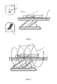
- FIG. 2 illustrates a schematic diagram of pilot scan according to one embodiment of the present disclosure
- FIG. 3 illustrates a schematic flow chart of a CT pilot image acquisition method according to one embodiment of the present disclosure
- FIG. 4 illustrates a schematic diagram of projection according to one embodiment of the present disclosure
- FIG. 5 illustrates a schematic diagram for obtaining a projection pixel value of a X-ray according to one embodiment of the present disclosure
- FIG. 6 schematically illustrates a pilot image obtained in the prior art and a pilot image obtained with a CT pilot image reconstruction method according to one embodiment of the present disclosure
- FIG. 7 illustrates a schematic structural diagram of a CT device according to one embodiment of the present disclosure.
- X-rays emitted by the X-ray tube are fan shaped, and constitute a beam having a certain thickness. Because the X-rays are not parallel but the detector has an arc shape, it cannot be ensured that each X-ray irradiated on the detector is perpendicular to the plane of the detector, which results in an energy deviation between the received X-rays and the emitted X-rays. In addition, when the X-rays penetrate the scanning object and encounter obstacles, diffraction and other physical phenomenon may occur based on X-ray's own property. Because different mediums may cause different effects on the X-rays, data received by the detector also has a deviation. A CT device in the conventional art only scans at a single angle, which may result in geometric distortion in obtained pilot images because of the reasons mentioned above. Therefore, a CT pilot image acquisition method is provided in this disclosure to solve the problem.
- FIG. 2 a schematic diagram of pilot scan according to an embodiment of the present disclosure is illustrated.
- Helical scan is adopted in the embodiment.
- a scanning trajectory indicated by a number “6” is adopted in the prior art, while a scanning trajectory indicated by a number “7” is adopted in the present disclosure.
- the helical scan trajectory is adopted in the embodiment of the present disclosure, which means the X-ray tube and the detector are not static, but have a helical trajectory.
- Embodiments of the present disclosure are described based on the schematic diagram of pilot scan shown in FIG. 2 .
- Table 1 in order to facilitate the description of embodiments, a plurality of parameters for describing embodiments of the present disclosure are defined in Table 1.
- FIG. 3 illustrates a schematic flow chart of CT pilot image acquisition method according to one embodiment of the present disclosure.
- the method may include the steps of 301 , 302 , 303 and 304 .
- step 301 a helical scan is performed on a predetermined area to be scanned to obtain scanning data.
- a scanning area is predetermined before the helical scan. Taking a lesion area (such as a heart are as an example, the scanning area is determined to be the heart area in a range of 40 centimeters from the neck. In the process of helical scan, the helical scan is performed in the range of the scanning area to obtain the scanning data.
- X-rays are adopted to scan, energy of the emitted X-rays is known.
- absorption of the X-rays is different in different parts of the scanning object, so that energy received by the detector is different at different positions.
- the X-ray energy received by the detector is the scanning data in this disclosure.
- the patient table which carries the scanning object, may move along the horizontal direction to cover the scanning area, so as to obtain the scanning data.
- the moving direction of the patient table may be a forward direction or a backward direction.
- scanning time may be expressed as Equation (1):
- a main fact impacting the X-ray dose is the scanning time T.
- a large pitch scan should be adopted, which means the pitch P should be greater than 1.
- the current I mA of the X-ray tube should be reduced as much as possible, as long as the image quality can meet practical requirements.
- P and I mA should be determined under the premise that the X-ray dose is not greater than a scanning X-ray dose in an original pilot image, where the original pilot image is a pilot image obtained with conventional methods.
- the scanning may be performed with a low dose and a large pitch, where the large pitch is larger than 1.
- the pitch may be less than 1 in practical application.
- the X-ray dose for obtaining pilot image may be different when different pitches are adopted.
- the pitch may be adjusted according to practical application environment, and is not limited in the present disclosure. Besides, as long as the image quality can meet practical requirement, an irradiation time, during which the scanning object receives the X-ray, may be reduced by increasing the rotation speed of the gantry and the slice number of the detector.
- the X-ray dose in embodiments of this disclosure may be close to an X-ray dose in a normal pilot image by increasing the rotation speed of the gantry and the slices of the detector, where the normal pilot image is a pilot image obtained with conventional methods.
- step 302 a tomographic image is reconstructed based on the scanning data.
- a thickness of the tomographic image and a distance between two adjacent tomographic images may be adjusted according to actual needs.
- step 303 at a predetermined positioning angle, a parallel beam projection is performed on the tomographic image by using a virtual parallel X-ray beam, so as to obtain projection data.
- FIG. 4 illustrates a schematic diagram of the parallel beam projection. As shown in FIG.
- a dot line is perpendicular to the direction of the parallel X-ray beam, and passes through the scan center “O”; and f(x′,y′) is the tomographic image.
- FIG. 5 illustrates a schematic diagram for obtaining spatial coordinates of the point A.
- the tomographic image includes a plurality of grids. After obtaining the spatial coordinates of the point A, four known points (four pixels close to the point A, but the number of the points is not limited to four) is determined in four adjacent areas corresponding to the point A.
- pixel values corresponding to B, C, D and E are f B (x B ,y B ), f C (x C ,y C ), f D (x D ,y D ), and f E (x E ,y E ) respectively.
- Distances from the four points to the point A are D 1 , D 2 , D 3 and D 4 respectively.
- Different weights are set based on the distances from the four points to the point A. The larger the distance is, the smaller the weight is.
- Pixel value f A (x A ,y A ) of the point A referring as P R (S′), is obtained with a linear interpolation method.
- a projection pixel value of the X-ray, on which the point A is, is obtained by adding pixel values of the points selected on the X-ray, which may be expressed as an equation shown below:
- I p ⁇ ( ⁇ , S ′ ) ⁇ R ⁇ [ - R Max , R Max ] ⁇ P R ⁇ ( S ′ ) .
- step 304 a CT pilot image is re-binned at the predetermined positioning angle based on the projection data.
- projection data of each X-ray may be obtained.
- Projection data of each X-ray passing through the tomographic image can constitute a “line”. Because the tomographic image has a thickness, the “line” has a thickness.
- a plurality of “lines” are obtained. Based on a sequence of the tomographic images, an image is re-binned by arranging the “lines”, which is the pilot image.
- helical scanning method is adopted to scan.
- Scanning data at any projection angle can be obtained by helical scan.
- the tomographic image is reconstructed based on the scanning data.
- the projection data of each tomographic image is obtained by performing a parallel beam projection on the tomographic images.
- the pilot image at the predetermined positioning angle is re-binned based on the projection data.
- the parallel beam projection can eliminate geometric distortions of the pilot image. Therefore, the pilot image can reflect the actual structure of the scanning object clearer and be more accurate.
- images obtained in embodiments of the present disclosure are not a pilot image at a single angle. Different pilot images are obtained at different positioning angle. It should be noted that, if the dose of the X-ray is greater, the penetration ability of the X-ray is stronger when the X-ray passes through the scanning object, and the result is more accurate. Based on the embodiment mentioned above, under a premise of a low X-ray dose, the value of I mA adopted in scanning process is generally far lower than that of helical scan in other application. Therefore, the scanning data has a great deal of noise. If the scanning data obtained in the step 301 is directly processed, the quality of the tomographic image may be affected by the noise. For example, the quality of the pilot image may be adversely affected by image edge blur.
- the noise smoothing process may include: analyzing a cause and characteristics of noises of the scanning data; and performing an adaptive suppression based on the characteristics of the noise to reduce the impact of noise on the tomographic image.
- a frequency division method is used to divide the tomographic image into multi-frequency images. Then, noise suppression and edge protection are performed based on different characteristics of the noises at different frequencies, so that a tomographic image suitable for parallel beam projection is obtained.
- pilot image After pilot image is obtained, a plurality of operations, such as cutting, translation, noise suppression, edge enhancement, etc, may be performed on the pilot image obtained after the parallel beam projection so as to obtain a higher quality pilot image.
- helical scan is adopted to obtain the pilot image.
- the method for obtaining pilot images at different projection angle can provide a basis for adjusting X-ray dose in a low dose scanning with an X-ray tube.
- an X-ray dose corresponding to an angle between the front side and the lateral side, is calculated.
- the X-ray dose is obtained based on an interpolation operation on a dose corresponding to the front side scan and a dose corresponding to the lateral side scan.
- the X-ray doses corresponding to different angles obtained by calculation cannot provide a good dose reference to an actual scan.
- the X-ray dose obtained by calculation is always great in practical application.
- the scanning object is scanned at any angles, so that optimal doses for scanning at different angles can be provided by acquiring quality of the pilot image. Therefore, for the dose adjustment of the X-ray tube in subsequent steps, pilot images obtained by this method can achieve a low dose scan, and provide more accurate dose reference information.
- FIG. 6 for a same scanning object and a same scanning area, an original pilot image obtained in the conventional art and a pilot image obtained in embodiments of the present disclosure are illustrated.
- the portions defined by the ellipses in FIG. 6 are supposed to be symmetric, but the portion defined by the ellipse in the original pilot image obtained in the conventional art is significant distorted. While the pilot image obtained in embodiments of the present disclosure is clearer, and has no geometric distortion.
- a CT device is provided in embodiments of the present disclosure.
- FIG. 7 a schematic structural diagram of a CT device is illustrated according to one embodiment.
- the device may include:
- a scanning unit 701 adapted for performing a helical scan on a predetermined area to be scanned, so as to obtain scanning data
- a tomographic image acquisition unit 702 adapted for reconstructing a tomographic image based on the scanning data
- a projection processing unit 703 adapted for performing, at a predetermined positioning angle, a parallel beam projection on the tomographic image by using a virtual parallel X-ray beam, so as to obtain projection data;
- a pilot image re-binning unit 704 adapted for re-binning a CT pilot image at the predetermined positioning angle based on the projection data.
- pilot image re-binning unit 704 may include:
- composition unit adapted for compositing an image based on the projection data to obtain a composited image
- a determining unit adapted for defining the composited image as the CT pilot image.
- the pilot image re-binning unit 704 may further include:
- a first denoising unit adapted for performing a denoising process on the composited image to obtain a denoised image
- the determining unit is adapted for defining the denoised image as the CT pilot image.
- the pilot image re-binning unit 704 may further include: a second denoising unit, adapted for, after the helical scan is performed on a predetermined area to be scanned and the scanning data is obtained, performing a denoising process on the obtained scanning data to obtain denoised scanning data, and defining the denoised scanning data as a basis for reconstructing the tomographic image.
- a second denoising unit adapted for, after the helical scan is performed on a predetermined area to be scanned and the scanning data is obtained, performing a denoising process on the obtained scanning data to obtain denoised scanning data, and defining the denoised scanning data as a basis for reconstructing the tomographic image.
Landscapes
- Health & Medical Sciences (AREA)
- Life Sciences & Earth Sciences (AREA)
- Engineering & Computer Science (AREA)
- Medical Informatics (AREA)
- Physics & Mathematics (AREA)
- General Health & Medical Sciences (AREA)
- Nuclear Medicine, Radiotherapy & Molecular Imaging (AREA)
- Radiology & Medical Imaging (AREA)
- Heart & Thoracic Surgery (AREA)
- Animal Behavior & Ethology (AREA)
- Optics & Photonics (AREA)
- Pathology (AREA)
- High Energy & Nuclear Physics (AREA)
- Biomedical Technology (AREA)
- Biophysics (AREA)
- Molecular Biology (AREA)
- Surgery (AREA)
- Veterinary Medicine (AREA)
- Public Health (AREA)
- Computer Vision & Pattern Recognition (AREA)
- Theoretical Computer Science (AREA)
- General Physics & Mathematics (AREA)
- Pulmonology (AREA)
- Apparatus For Radiation Diagnosis (AREA)
- Quality & Reliability (AREA)
Abstract
Description
| TABLE 1 |
| parameters and definition |
| Parameter | |
| Name | Definition |
| f(x′, y′) | low-dose tomographic image |
| β | projection angle |
| Ip(β, S′) | projective result |
| O | scanning center |
|
|
x-coordinate data of pixel (with respect to the scanning center) |
| y | y-coordinate data of pixel (with respect to the scanning |
| center) | |
| M | moving distance of the patient table in a helical scan |
| circle | |
| Ns | slice number of an X-ray detector |
| Δs | width of each slice of an X-ray detector |
| P | |
| L | scanning length |
| ImA | scanning current (mA) |
| R | distance from a point of a X-ray to the center point of the |
| X-ray | |
| S | distance from a X-ray to a center X-ray |
| T | scanning time |
| t | rotation time of a gantry |
| D | X-ray dose (mAs) |
| RMax | maximum distance from a point to a center point on a |
| projection optical path | |
D=I mA ×T Equation (2)
y′=x′ctgβ+S
Claims (10)
Applications Claiming Priority (3)
| Application Number | Priority Date | Filing Date | Title |
|---|---|---|---|
| CN201310301555 | 2013-07-17 | ||
| CN2013103015555A CN103315764A (en) | 2013-07-17 | 2013-07-17 | Method for acquiring CT locating images and CT device |
| CN201310301555.5 | 2013-07-17 |
Publications (2)
| Publication Number | Publication Date |
|---|---|
| US20150023464A1 US20150023464A1 (en) | 2015-01-22 |
| US9345444B2 true US9345444B2 (en) | 2016-05-24 |
Family
ID=49185017
Family Applications (1)
| Application Number | Title | Priority Date | Filing Date |
|---|---|---|---|
| US14/142,963 Active 2034-06-27 US9345444B2 (en) | 2013-07-17 | 2013-12-30 | CT pilot image acquisition method and CT device |
Country Status (2)
| Country | Link |
|---|---|
| US (1) | US9345444B2 (en) |
| CN (1) | CN103315764A (en) |
Families Citing this family (6)
| Publication number | Priority date | Publication date | Assignee | Title |
|---|---|---|---|---|
| DE102013200337B4 (en) * | 2013-01-11 | 2021-11-11 | Siemens Healthcare Gmbh | Method, computer tomograph and computer program product for determining intensity values of an X-ray radiation for dose modulation |
| CN107495976B (en) * | 2016-06-14 | 2021-01-01 | 上海联影医疗科技股份有限公司 | Method and device for acquiring maximum value and gray value image in image reconstruction |
| CN108420449A (en) * | 2018-02-06 | 2018-08-21 | 赛诺威盛科技(北京)有限公司 | Single moves the method that bed realizes CT multi-angle locating plates |
| CN110782422A (en) * | 2019-10-21 | 2020-02-11 | 南京安科医疗科技有限公司 | Method for synthesizing X-ray film and marking through CT image |
| CN111968112B (en) * | 2020-09-02 | 2023-12-26 | 广州海兆印丰信息科技有限公司 | CT three-dimensional positioning image acquisition method and device and computer equipment |
| CN113749680B (en) * | 2021-08-05 | 2023-08-04 | 中国人民解放军总医院 | Scanning positioning method, scanning positioning device, storage medium and computer equipment |
Citations (6)
| Publication number | Priority date | Publication date | Assignee | Title |
|---|---|---|---|---|
| US20070237286A1 (en) * | 2006-04-06 | 2007-10-11 | Yasuhiro Imai | X-Ray CT Apparatus |
| US20090086888A1 (en) * | 2007-10-02 | 2009-04-02 | Akira Hagiwara | X-ray ct apparatus and image reconstruction method |
| CN101427924A (en) | 2008-07-16 | 2009-05-13 | 山东省肿瘤医院 | Method for acquiring complete anatomy image with segmenting pencil-beam CT image by split joint |
| US20090202126A1 (en) * | 2008-02-08 | 2009-08-13 | Xiangyang Tang | Methods and apparatus for hybrid cone beam image reconstruction |
| CN102573640A (en) | 2010-10-06 | 2012-07-11 | 株式会社东芝 | Medical image processing device and medical image processing program |
| CN103164593A (en) | 2011-12-10 | 2013-06-19 | 西安百利信息科技有限公司 | Urology remote consultation system based on computed tomography (CT) abdominal X-ray plain film examination |
-
2013
- 2013-07-17 CN CN2013103015555A patent/CN103315764A/en active Pending
- 2013-12-30 US US14/142,963 patent/US9345444B2/en active Active
Patent Citations (8)
| Publication number | Priority date | Publication date | Assignee | Title |
|---|---|---|---|---|
| US20070237286A1 (en) * | 2006-04-06 | 2007-10-11 | Yasuhiro Imai | X-Ray CT Apparatus |
| US20090086888A1 (en) * | 2007-10-02 | 2009-04-02 | Akira Hagiwara | X-ray ct apparatus and image reconstruction method |
| CN101401726A (en) | 2007-10-02 | 2009-04-08 | Ge医疗系统环球技术有限公司 | X-ray CT apparatus |
| US20090202126A1 (en) * | 2008-02-08 | 2009-08-13 | Xiangyang Tang | Methods and apparatus for hybrid cone beam image reconstruction |
| CN101427924A (en) | 2008-07-16 | 2009-05-13 | 山东省肿瘤医院 | Method for acquiring complete anatomy image with segmenting pencil-beam CT image by split joint |
| CN102573640A (en) | 2010-10-06 | 2012-07-11 | 株式会社东芝 | Medical image processing device and medical image processing program |
| US20120263359A1 (en) | 2010-10-06 | 2012-10-18 | Toshiba Medical Systems Corporation | Medical image processing apparatus and medical image processing program |
| CN103164593A (en) | 2011-12-10 | 2013-06-19 | 西安百利信息科技有限公司 | Urology remote consultation system based on computed tomography (CT) abdominal X-ray plain film examination |
Non-Patent Citations (4)
| Title |
|---|
| "Radiation Oncology Physics", Yimin Hu, Atomic Energy Press, Sep. 30, 1999. n |
| Linghong Zhou et al., "CT-Based Simulation in Radiation Therapy", 3 pages. |
| The 3rd Office Action issued on Oct. 29, 2015 regarding the Chinese priority patent application (Appl.No. 201310301555.5). |
| The second Office Action issued on May 21, 2015 regarding the Chinese priority patent application (Appl.No. 201310301555.5). |
Also Published As
| Publication number | Publication date |
|---|---|
| US20150023464A1 (en) | 2015-01-22 |
| CN103315764A (en) | 2013-09-25 |
Similar Documents
| Publication | Publication Date | Title |
|---|---|---|
| US9345444B2 (en) | CT pilot image acquisition method and CT device | |
| US10049467B2 (en) | Apparatus and method for reconstructing medical image | |
| JP4695867B2 (en) | Non-uniform view weighted tomosynthesis method and apparatus | |
| CN101854863B (en) | Movable wedge for improved image quality in 3D X-ray imaging | |
| US8818065B2 (en) | Methods and apparatus for scatter correction for CBCT system and cone-beam image reconstruction | |
| US6366638B1 (en) | Methods and apparatus for CT scout image processing | |
| EP1716809B1 (en) | Tomogram reconstruction method and tomograph | |
| JP5171215B2 (en) | X-ray CT system | |
| US7433507B2 (en) | Imaging chain for digital tomosynthesis on a flat panel detector | |
| JP5090680B2 (en) | X-ray CT system | |
| US10255696B2 (en) | System and method for image reconstruction | |
| US20110150173A1 (en) | X-ray ct system and control method for same | |
| US20010048732A1 (en) | Two-dimensional slot x-ray bone densitometry, radiography and tomography | |
| KR20070077093A (en) | Image display apparatus and x-ray ct apparatus | |
| CN102846333A (en) | Method and system for scatter correction in x-ray imaging | |
| US9196064B2 (en) | Image reconstruction method and device for tilted helical scan | |
| Sun et al. | Correction for patient table‐induced scattered radiation in cone‐beam computed tomography (CBCT) | |
| KR20200142057A (en) | Image analysis method, segmentation method, bone density measurement method, learning model creation method, and image creation device | |
| US20140362970A1 (en) | System and method of correcting banding artifacts in cardiac ct | |
| US8639007B2 (en) | Generating two-dimensional projection images from helical data | |
| US10070841B2 (en) | Arithmetic device, X-ray CT apparatus, and image reconstruction method | |
| US7239730B2 (en) | Method and apparatus for volume scoring calcification concentrations of a CT scan | |
| US11801017B2 (en) | Focused tomography | |
| Yang et al. | Scattering estimation for cone-beam CT using local measurement based on compressed sensing | |
| CN111297386A (en) | CT data positioning method |
Legal Events
| Date | Code | Title | Description |
|---|---|---|---|
| AS | Assignment |
Owner name: SHENYANG NEUSOFT MEDICAL SYSTEMS CO., LTD., CHINA Free format text: ASSIGNMENT OF ASSIGNORS INTEREST;ASSIGNORS:LOU, SHANSHAN;ZHENG, HAN;REEL/FRAME:031872/0130 Effective date: 20131223 |
|
| STCF | Information on status: patent grant |
Free format text: PATENTED CASE |
|
| MAFP | Maintenance fee payment |
Free format text: PAYMENT OF MAINTENANCE FEE, 4TH YEAR, LARGE ENTITY (ORIGINAL EVENT CODE: M1551); ENTITY STATUS OF PATENT OWNER: LARGE ENTITY Year of fee payment: 4 |
|
| AS | Assignment |
Owner name: NEUSOFT MEDICAL SYSTEMS CO., LTD., CHINA Free format text: CHANGE OF NAME;ASSIGNOR:SHENYANG NEUSOFT MEDICAL SYSTEMS CO., LTD.;REEL/FRAME:052398/0489 Effective date: 20200329 |
|
| MAFP | Maintenance fee payment |
Free format text: PAYMENT OF MAINTENANCE FEE, 8TH YEAR, LARGE ENTITY (ORIGINAL EVENT CODE: M1552); ENTITY STATUS OF PATENT OWNER: LARGE ENTITY Year of fee payment: 8 |