US934110A - Apparatus for removing lye from fabrics. - Google Patents
Apparatus for removing lye from fabrics. Download PDFInfo
- Publication number
- US934110A US934110A US39958507A US1907399585A US934110A US 934110 A US934110 A US 934110A US 39958507 A US39958507 A US 39958507A US 1907399585 A US1907399585 A US 1907399585A US 934110 A US934110 A US 934110A
- Authority
- US
- United States
- Prior art keywords
- rollers
- steam
- fabric
- pipes
- lye
- Prior art date
- Legal status (The legal status is an assumption and is not a legal conclusion. Google has not performed a legal analysis and makes no representation as to the accuracy of the status listed.)
- Expired - Lifetime
Links
- 239000004744 fabric Substances 0.000 title description 22
- HEMHJVSKTPXQMS-UHFFFAOYSA-M Sodium hydroxide Chemical compound [OH-].[Na+] HEMHJVSKTPXQMS-UHFFFAOYSA-M 0.000 description 20
- 235000011121 sodium hydroxide Nutrition 0.000 description 12
- WXOMTJVVIMOXJL-BOBFKVMVSA-A O.O.O.O.O.O.O.O.O.O.O.O.O.O.O.O.O.O.O.O.O.O.O[Al](O)O.O[Al](O)O.O[Al](O)O.O[Al](O)O.O[Al](O)O.O[Al](O)O.O[Al](O)O.O[Al](O)O.O[Al](O)OS(=O)(=O)OC[C@H]1O[C@@H](O[C@]2(COS(=O)(=O)O[Al](O)O)O[C@H](OS(=O)(=O)O[Al](O)O)[C@@H](OS(=O)(=O)O[Al](O)O)[C@@H]2OS(=O)(=O)O[Al](O)O)[C@H](OS(=O)(=O)O[Al](O)O)[C@@H](OS(=O)(=O)O[Al](O)O)[C@@H]1OS(=O)(=O)O[Al](O)O Chemical compound O.O.O.O.O.O.O.O.O.O.O.O.O.O.O.O.O.O.O.O.O.O.O[Al](O)O.O[Al](O)O.O[Al](O)O.O[Al](O)O.O[Al](O)O.O[Al](O)O.O[Al](O)O.O[Al](O)O.O[Al](O)OS(=O)(=O)OC[C@H]1O[C@@H](O[C@]2(COS(=O)(=O)O[Al](O)O)O[C@H](OS(=O)(=O)O[Al](O)O)[C@@H](OS(=O)(=O)O[Al](O)O)[C@@H]2OS(=O)(=O)O[Al](O)O)[C@H](OS(=O)(=O)O[Al](O)O)[C@@H](OS(=O)(=O)O[Al](O)O)[C@@H]1OS(=O)(=O)O[Al](O)O WXOMTJVVIMOXJL-BOBFKVMVSA-A 0.000 description 4
- 238000005517 mercerization Methods 0.000 description 4
- 229920006395 saturated elastomer Polymers 0.000 description 3
- 239000000969 carrier Substances 0.000 description 2
- 238000006073 displacement reaction Methods 0.000 description 2
- FDQGNLOWMMVRQL-UHFFFAOYSA-N Allobarbital Chemical compound C=CCC1(CC=C)C(=O)NC(=O)NC1=O FDQGNLOWMMVRQL-UHFFFAOYSA-N 0.000 description 1
- 238000004140 cleaning Methods 0.000 description 1
- 230000003014 reinforcing effect Effects 0.000 description 1
- XLYOFNOQVPJJNP-UHFFFAOYSA-N water Substances O XLYOFNOQVPJJNP-UHFFFAOYSA-N 0.000 description 1
Images
Classifications
-
- D—TEXTILES; PAPER
- D06—TREATMENT OF TEXTILES OR THE LIKE; LAUNDERING; FLEXIBLE MATERIALS NOT OTHERWISE PROVIDED FOR
- D06C—FINISHING, DRESSING, TENTERING OR STRETCHING TEXTILE FABRICS
- D06C7/00—Heating or cooling textile fabrics
Definitions
- This invention relates to an apparatus for removing lye from fabrics, which have been saturated with soda-lye, for the purpose of mercerization.
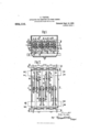
- Figure 1 is a vertical cross section through the apparatus on the line A.B of Fig. 2;
- Fig. 2 is a plan view showing the steam pipes, and Fig. 3 a vertical longitudinal section through the apparatus;
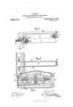
- Fig. 4 shows partially in side elevation and partially in longitudinal section a pair of mangling rollers in combination with the carrier, and
- Fig. 5 a plan of the same;
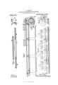
- Fig. 6 shows on a smaller scale a side elevation of the apparatus in combination with the stretching frame of the mercerization machine, and Fig. 7 a plan of the same;
- Fig. 8 shows 011 a larger scale a horizontal section, and
- Fig. 9 a cross section through the steamjets;
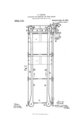
- Fig. 10 shows on a larger scale a part of the chain which stretches the fabric in its breadth, whereas
- Fig. 11 shows also on a larger scale a side elevation of one link of the chain and a cross section through the guide for the chain.
- 1 is a closable box, through which the fabric- 2 saturated with lye is passed in the direction of the arrow shown in the drawing.
- two girders 3, 4 are arranged at the sides of the box, on which girders the cross-beam 5 rests.
- the slides 6 and also the slides 7 are each provided with three rollers 9, 10, 11 by means of which each of the lower mangling rollers is supported securely at both ends.
- steam pipes 12, 13 are provided at the two sides of the box 1, from which pipes the transverse pipes 14 extend through the uppipes 14 at the same time serve as guides for the slides 15, 16; the latter are also arranged so as to be capable of being displaced and secured, and are each provided with two guide-rollers 19, 20 for the purpose of supporting the upper mangling rollers 18.
- the upper mangling rollers 18 consequently press by means of their own weight on the lower mangling rollers 8 and are prevented from moving laterally out of position by means of the rollers 19, 20.
- the pipes 21 branch off from the steam pipe 12, the branch pipes 23 being connected with said pipes 21.
- the branch pipes 23 terminate in the perforated steam-jet pipes 24, 25 through which the steam is directed against the back surface of the fabric 2 as clearly shown in Fig. 1.
- the steam pipes 14 are connected through the connecting pipes 26 with the perforated steam-je -pipes 27, 28, which serve to direct the steam against the upper or front surface of the fabric.
- the steam pipes 27 may be suitably varied in length by drawing out or pushing in the parts 30, 31, shown in Fig. 8.
- the walls 80, 81 of the box are provided with slots 82.
- the slots 82 two girders 35 are disposed parallel to each other.
- irders 35 may be shifted in the direction of the arrows 83, 84 (Fig. 2 and Fig. 4.)
- the carriers 33 are fastened by means of the flanges 34 (Fig. 4-5).
- a bracket or lug 36 are fastened. Every bracket or lug is provided with a slot 85.
- a screw bolt 38 which is introduced in the slot 85.
- a bracket or lug 37 is fastened. Every bracket is provided with a slot 86.
- a screw bolt 39 is fastened, which is introduced in the slot 86.
- the rollers 8, 18 are alternately connected with one of the two girders 35.
- the lines 40, 40 indicate the ends of the lower roller of the first pair of mangling rollers and the lines 41, 41 the ends of appertaining upper rollers; the lines 42, 42 indicate the ends of the lower roller of the other pair of mangling rollers and the lines 43-, 43 theends of the appertaining upper roller.
- 45 is the stretchlng-frame of the mercerization machines'ervmg as guide for the clamping chains 49, 49C.
- the E two sprocket wheels 51, 51 are rigidly c011 nected with the bevel wheels 67, 67 so that they rotate with the same and thus move the chain in the direction ofthe arrows 68-, 68.
- the chains 49, 49. consist of the links (Fig. 105) which are connected by means of the pins 75. 'Each link of the chainis provided at 76 with a weighted lever 7 7 the end of which presses the fabric at'70 against the clearly shown in Fi 11. v
- the fabric will be stretched in f breadth when it passes through the stretchling frame of the mercerization machine in the direction of the arrows 68, 68". i r
- the mode of operation'of the apparatus according to the present invention is as follows :When the fabric 2 passes through I the receptacle 1 in the direction of the arrows 68, 68 (Fig. 7) steam is directed by the steam-jet pipes 24-, 25 and 27 28 against both sides of the fabric. At the same time the fabric is stretched in breadth bythe chains 49, 49C On account of the action of *the steam the soda-lye is diluted and at the same timeheated to such a'high temperature that the fabric is able to leave the stretching frame without shrinking. Owing to the fabricbeing stretched in breadth the steam can more easily penetrate the fabric and remove thelye.
- The'condensed water collects with the lye at the bottom of the receptacle 1 and canthen be removed from the same for the purpose of being further treated.
- the pair of the ma'ngling rollers 8, 1 8 may be displaced one toward the other in the direction of their axis according to the breadth of the fabric to be treated,
- the 'girders mustbe' -pla''edi n the sl'ots i82 indirection of'the arrows 83, 85L (Fig. 2 and Fig. ifwith the nu-angling reliefs being 'connected with them.
Landscapes
- Engineering & Computer Science (AREA)
- Textile Engineering (AREA)
- Treatment Of Fiber Materials (AREA)
Description
0. VENTER. APPARATUS FOR REMOVING LYE FROM FABRICS.
APPLICATION FILED OUT. 28, 1907. I
- Patented Sept. 14,1909.
4 SHEETS-SHEET 1.
vmlka 2 M 4 Fig.2.
munzw av GRAHAM ca. PHOHLUTNDGRAPH LVENTER. v y APPARATUS FOR BEMGVING LYE FROM FABRICS.
APPLICATION FILED OUT. 28, 1907. 934,1 Patented Sept. 14, 1909.
4 SHEETS-SHEET 2.
34 g 373 Fig.5. 1 I I 18 E 4a I A.
a: 25 h: 21 J H F 5 g M &
. f y off OZZJ a i ANDREW. a. GRAHAM 00,, Puumuwoummisns. WASHINGTON. \1 c.
Patented Sept. 14, 1909. 4 SHEETSSHEET 3.
0. "VI-INTER. APPARATUS FOR REMOVING LYE FROM FABRIUS. APPLICATION FILED OUT. 28, 1907.
m "A a 2 a pm. ma ns ANDREW. a. awmm cu; Puom-Lrmoampu ns. wAsummou. nv cv 0. VENTER.
APPARATUS FOR REMOVING LYE FROM PABRIOS.
APPLICATION FILED OUT. 28, 1907.
934;, 1 1 O, Patented Sept. 14, 1909.
4 SHEETS-SHEET 4.
ANDREW. B. amnm co. FNDTO-UTHOGRAPKERS. WASHINGTUNI'AJ. u
o'rro VENTER, OF'CI-IEMNITZ, GERMANY.
APPARATUS FOR REMOVING LYE, FROM FABRICS.
Specification of Letters Patent.
Patented Sept. 14, 1909.
Application filed October 28, 1907. Serial No. 399,585.
To all whom it may concern;
Be it known that I, OTTO VENTER, a subject of the German Emperor, and residing at Chemnitz, in the Kingdom of Saxony, Empire of Germany, have invented certain new and useful Improvements in Apparatus for Removing Lye from Fabrics Saturated with Soda-Lye, of which the following is the specification.
This invention relates to an apparatus for removing lye from fabrics, which have been saturated with soda-lye, for the purpose of mercerization.
One embodiment of my invention is represented by way of example in the annexed drawings, in which: 7
Figure 1 is a vertical cross section through the apparatus on the line A.B of Fig. 2; Fig. 2 is a plan view showing the steam pipes, and Fig. 3 a vertical longitudinal section through the apparatus; Fig. 4 shows partially in side elevation and partially in longitudinal section a pair of mangling rollers in combination with the carrier, and Fig. 5 a plan of the same; Fig. 6 shows on a smaller scale a side elevation of the apparatus in combination with the stretching frame of the mercerization machine, and Fig. 7 a plan of the same; Fig. 8 shows 011 a larger scale a horizontal section, and Fig. 9 a cross section through the steamjets; Fig. 10 shows on a larger scale a part of the chain which stretches the fabric in its breadth, whereas Fig. 11 shows also on a larger scale a side elevation of one link of the chain and a cross section through the guide for the chain.
As is clearly shown in the drawings, 1 is a closable box, through which the fabric- 2 saturated with lye is passed in the direction of the arrow shown in the drawing. As clearly shown in Fig. 3 two girders 3, 4 are arranged at the sides of the box, on which girders the cross-beam 5 rests. On each of the latter two slides 6, 7 formed as bearing standards are supported, seats to becapable of being shifted and secured, said slides serving to support the lower mangling rollers 8. For this purpose the slides 6 and also the slides 7 are each provided with three rollers 9, 10, 11 by means of which each of the lower mangling rollers is supported securely at both ends.
For the purpose of supplying the steam, steam pipes 12, 13 are provided at the two sides of the box 1, from which pipes the transverse pipes 14 extend through the uppipes 14 at the same time serve as guides for the slides 15, 16; the latter are also arranged so as to be capable of being displaced and secured, and are each provided with two guide-rollers 19, 20 for the purpose of supporting the upper mangling rollers 18. The upper mangling rollers 18 consequently press by means of their own weight on the lower mangling rollers 8 and are prevented from moving laterally out of position by means of the rollers 19, 20. As shown in Fig. 3, the pipes 21 branch off from the steam pipe 12, the branch pipes 23 being connected with said pipes 21. The branch pipes 23 terminate in the perforated steam-jet pipes 24, 25 through which the steam is directed against the back surface of the fabric 2 as clearly shown in Fig. 1. The steam pipes 14 are connected through the connecting pipes 26 with the perforated steam-je -pipes 27, 28, which serve to direct the steam against the upper or front surface of the fabric. The steam pipes 27 may be suitably varied in length by drawing out or pushing in the parts 30, 31, shown in Fig. 8.
The walls 80, 81 of the box are provided with slots 82. In the slots 82 two girders 35 are disposed parallel to each other. The
irders 35 may be shifted in the direction of the arrows 83, 84 (Fig. 2 and Fig. 4.) On the girders 35 the carriers 33 are fastened by means of the flanges 34 (Fig. 4-5). To each of the carriers 33 a bracket or lug 36 are fastened. Every bracket or lug is provided with a slot 85. In the rollers is fastened a screw bolt 38, which is introduced in the slot 85. To each of the girders 35 a bracket or lug 37 is fastened. Every bracket is provided with a slot 86. In each of the lower rollers 8 a screw bolt 39 is fastened, which is introduced in the slot 86. In said manner the rollers 8, 18 are alternately connected with one of the two girders 35.
In Fig. 3 the lines 40, 40 indicate the ends of the lower roller of the first pair of mangling rollers and the lines 41, 41 the ends of appertaining upper rollers; the lines 42, 42 indicate the ends of the lower roller of the other pair of mangling rollers and the lines 43-, 43 theends of the appertaining upper roller.
The displacement of the girders 35 in the direction of the arrows 44 makes it possible to treat with the mangling rollers fabrics per part of the box 1. vThese transverse of different breadth, but the breadth of the fabric must not exceed twice the length of the mangling rollers however.
Referring now to Figs. 6 to 4'5, 45 is the stretchlng-frame of the mercerization machines'ervmg as guide for the clamping chains 49, 49C. The chains 5L9, {L V-engage the ga e with the two bevel wheels 67, 67; The E two sprocket wheels 51, 51, are rigidly c011 nected with the bevel wheels 67, 67 so that they rotate with the same and thus move the chain in the direction ofthe arrows 68-, 68.
The chains 49, 49. consist of the links (Fig. 105) which are connected by means of the pins 75. 'Each link of the chainis provided at 76 with a weighted lever 7 7 the end of which presses the fabric at'70 against the clearly shown in Fi 11. v
As at the in-coming end of the machine,
part 78 andthus frnil'y holds the same,ras:f'
2112. at 72', the distance between the two I chain s49, 4:9 is less than atthe out-going end, '2'. e. at 73, the fabric will be stretched in f breadth when it passes through the stretchling frame of the mercerization machine in the direction of the arrows 68, 68". i r
p The mode of operation'of the apparatus according to the present invention is as follows :When the fabric 2 passes through I the receptacle 1 in the direction of the arrows 68, 68 (Fig. 7) steam is directed by the steam-jet pipes 24-, 25 and 27 28 against both sides of the fabric. At the same time the fabric is stretched in breadth bythe chains 49, 49C On account of the action of *the steam the soda-lye is diluted and at the same timeheated to such a'high temperature that the fabric is able to leave the stretching frame without shrinking. Owing to the fabricbeing stretched in breadth the steam can more easily penetrate the fabric and remove thelye. The'condensed water collects with the lye at the bottom of the receptacle 1 and canthen be removed from the same for the purpose of being further treated. The pair of the ma'ngling rollers 8, 1 8 may be displaced one toward the other in the direction of their axis according to the breadth of the fabric to be treated,
For this purpose the 'girders mustbe' -pla''edi n the sl'ots i82 indirection of'the arrows 83, 85L (Fig. 2 and Fig. ifwith the nu-angling reliefs being 'connected with them.
According to the displacement of thepairs.
ofmaagiia rollers-the 51161886,? bff-iiaeh j" each upper roller onthe .pipes 115.
I I am, awaret-hat 1'nachins a e! ovvfn'iii which fabrics asstetween'aser e (if ion. er steam bein way through of the lower ;rollers; must be idisplacedionjq the beams 5 as wellas the slides 15, 16 of sup li dfto reinforcing as e' fabric for megawat er cleaning the I, therefore doj ot tha seen ale-ans broadly; as the sarjne ave aa are emploveddirectly upon, and in combine f tion with-,the stretching frame or amm eeri'z'ing machine nd, the, fabric is therefore able to leave the stretching frame without shrinking and j r What I claim; is :f
.1. In apparauis'or thefty ed'stiiteti,l the combination, with a stretchingfrainef adapted to carry and stretch the. fabricpof a box inclosing' part of, said stretching V- frame, a plurality of pairs'ofrollers- -injsaid l box between which the fabricfcan pass'vvhile I beingstretched,and:means: in saidbox' for conducting steam against thefabric passing throiigh'said manglingrollers;
2. In apparatus of the character described the combinatiomwith'a g1rder,1ofa bracket thereon, a rollerf mounted with one end piv.-
oted insaidbracket,,acarrieronsaidigirder, a
a bracket on said carrier,- andanupperroll er 'mounted with one end pivotedinthe latter;
bracket, thepivoted endof theupper roller being;- opposed to the pivoted; endof the lower roller; I V V j 3. In apparatus of the character described,
the combination, with a girder,.of. a bracket thereon, a roller mounted withonefendpiW oted in said'bracket, acarrier on saidgirder,
a bracket on said carrier, and an upper roller mounted with one end pivoted intheglatter bracket, the pivoted on lower roller, a slide" carrying three rollers of HPPQIL-IOHQI'V}; being Opp t he pive 'cen d oft'hej-M for. supporting. the flower-roller, and a slide 7 the upper roller, I r
I carrying two rollers forsecuring' in position I In witness whereof" I; have l v i V. V v orr'o "vnmnafg Witnessesi -i KAR V BEL, V Dorm H. KOUJELAN Y my hand in presence of two witnessesfj
Priority Applications (1)
| Application Number | Priority Date | Filing Date | Title |
|---|---|---|---|
| US39958507A US934110A (en) | 1907-10-28 | 1907-10-28 | Apparatus for removing lye from fabrics. |
Applications Claiming Priority (1)
| Application Number | Priority Date | Filing Date | Title |
|---|---|---|---|
| US39958507A US934110A (en) | 1907-10-28 | 1907-10-28 | Apparatus for removing lye from fabrics. |
Publications (1)
| Publication Number | Publication Date |
|---|---|
| US934110A true US934110A (en) | 1909-09-14 |
Family
ID=3002533
Family Applications (1)
| Application Number | Title | Priority Date | Filing Date |
|---|---|---|---|
| US39958507A Expired - Lifetime US934110A (en) | 1907-10-28 | 1907-10-28 | Apparatus for removing lye from fabrics. |
Country Status (1)
| Country | Link |
|---|---|
| US (1) | US934110A (en) |
-
1907
- 1907-10-28 US US39958507A patent/US934110A/en not_active Expired - Lifetime
Similar Documents
| Publication | Publication Date | Title |
|---|---|---|
| IL33472A (en) | Tensionless fluid treating apparatus and method for textile webs | |
| US2821237A (en) | Pleating apparatus for pleating textile fabric | |
| NO126206B (en) | ||
| US1754089A (en) | Tentering machine | |
| US624884A (en) | Island | |
| US617561A (en) | Machine for mercerizing | |
| SU30186A1 (en) | Sheet Dryer | |
| US1926977A (en) | Garment cleaning machine | |
| US3264704A (en) | Drive for tentering chains | |
| US4102058A (en) | Fabric finishing machine | |
| US1595829A (en) | Fruit drier | |
| US2002096A (en) | Fabric expander for textile industry | |
| US1006231A (en) | Washing-machine. | |
| US2584754A (en) | Machine for the treating of web material | |
| US1535326A (en) | Machine for shrinking felt articles | |
| US3393463A (en) | Inverted steam chest mounting for ironing machines | |
| US63461A (en) | Improvement in machine foe drying cloth | |
| USRE17269E (en) | krantz | |
| US264407A (en) | Washing-machine | |
| US751019A (en) | Alonzo shaep | |
| US655546A (en) | Mercerizing apparatus. | |
| US1002473A (en) | Machine for laundrying. | |
| US661649A (en) | Mercerizing-machine. | |
| US819991A (en) | Machine for folding woven fabrics. | |
| US1490761A (en) | Loop drier |