US933915A - Wooden column. - Google Patents
Wooden column. Download PDFInfo
- Publication number
- US933915A US933915A US45868908A US1908458689A US933915A US 933915 A US933915 A US 933915A US 45868908 A US45868908 A US 45868908A US 1908458689 A US1908458689 A US 1908458689A US 933915 A US933915 A US 933915A
- Authority
- US
- United States
- Prior art keywords
- column
- dove
- tail
- edge
- faces
- Prior art date
- Legal status (The legal status is an assumption and is not a legal conclusion. Google has not performed a legal analysis and makes no representation as to the accuracy of the status listed.)
- Expired - Lifetime
Links
- 230000002045 lasting effect Effects 0.000 description 1
Images
Classifications
-
- F—MECHANICAL ENGINEERING; LIGHTING; HEATING; WEAPONS; BLASTING
- F16—ENGINEERING ELEMENTS AND UNITS; GENERAL MEASURES FOR PRODUCING AND MAINTAINING EFFECTIVE FUNCTIONING OF MACHINES OR INSTALLATIONS; THERMAL INSULATION IN GENERAL
- F16L—PIPES; JOINTS OR FITTINGS FOR PIPES; SUPPORTS FOR PIPES, CABLES OR PROTECTIVE TUBING; MEANS FOR THERMAL INSULATION IN GENERAL
- F16L9/00—Rigid pipes
- F16L9/22—Pipes composed of a plurality of segments
-
- Y—GENERAL TAGGING OF NEW TECHNOLOGICAL DEVELOPMENTS; GENERAL TAGGING OF CROSS-SECTIONAL TECHNOLOGIES SPANNING OVER SEVERAL SECTIONS OF THE IPC; TECHNICAL SUBJECTS COVERED BY FORMER USPC CROSS-REFERENCE ART COLLECTIONS [XRACs] AND DIGESTS
- Y10—TECHNICAL SUBJECTS COVERED BY FORMER USPC
- Y10T—TECHNICAL SUBJECTS COVERED BY FORMER US CLASSIFICATION
- Y10T403/00—Joints and connections
- Y10T403/70—Interfitted members
Definitions
- My improvement relates particularly to wooden columns formed of longitudinal .inter-engaging sections.
- the object of the invention is to provide a column in which the joints between the inter-engaging sections are of superior efficiency.
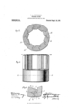
- Figure l is a sectional side elevation of a portion of a column embodying my improvement
- Fig. 2 is a transverse section on the line 2-2 of Fig. l
- Fig. 3 is a detail transverse sectional view showing one of the joints by which the sections or staves of the column are interengaged.
- each of said staves has at its left hand side, as viewed in Figs. 2 and 3, an outer face, l, which is approximately radial to the axis of the column and an inner face, 2, which is also approximately radial to the axis of the column but off-set from the face, l. From the outer portion of the face, 2, a face, 3, extends away from the face, 2, approximately perpendicular to the lat-ter.
- oblique dove-tail A, which is approximately on a line or plane bisecting the angle which would be formed by extending the faces, l and 3, until they meet or intersect and which dove-tail is at the same time at an angle of about forty-five degrees to a plane which is radial to the column axis and cuts the dovetail.
- said dove-tail hasin its outer portion a V-shape groove, 5.
- each of said sections or staves is shaped to conform, in reverse, to the left hand edge of each of said sections, faces, G, 7, and 8, on said left hand edge -being adapted, respectively, to meet the faces, l, 2, and 3, on another section, and a groove, 9, in said right hand edge being adapted to receive the dovetail, 4;, of another section.
- the sections or staves can be inter-engaged only by pushing A, A are the ,one endwise upon the other after entering the dove-tail, 4, into the groove, 9. In this manner one piece after another is forced into position until the column has been completed.
- a column composed of inter-engaging, longitudinal sections, each section having on one edge a dove-tail which is oblique to a plane which is radial to the column axis and cuts the dove-tail and the other edge having a groove conforming in reverse to said dovetail, substantially as described.
- a column composed of inter-engaging, longitudinal sections, each section having on one edge a grooved dove-tail which is oblique to a plane which is radial to the column axis and cuts the dove-tail and the other edge having a groove conforming in reverse to said dove-tail, substantially as described.
- a column composed of inter-engaging, longitiidinal sections having on one edge a face approximately radial to the column axis and having on said edge another face at an angle to the first mentioned face and having a dove-tail between said. faces, and having on its other edge two faces and a groove conforming in reverse to the faces and dove-tail of the other edge, substantially as described.
- a column composed of inter-engaging, longitudinal sections having on one edge a face approximately radial to the column axis and having on said edge another face at an angle to the first mentioned face and having a grooved dove-tail between said faces, and having on its other edge two faces and a groove conforming in reverse to the faces and dove-tail of the other edge, substantially as described.
Landscapes
- Engineering & Computer Science (AREA)
- General Engineering & Computer Science (AREA)
- Mechanical Engineering (AREA)
- Joining Of Building Structures In Genera (AREA)
Description
UNTED STATS t. E FFC.
CHARLES A. NICKERSON, OF KNOXVILLE, TENNESSEE.
WOODEN COLUMN.
Specification of Letters Patent.
To all whom it may concern:
Be it known that- I, CHARLES A. Nrcxnnson, a citizen of the United States, residing at Knoxville, in the county of Knox and State of Tennessee, have invented a new and useful improvement in Wooden Columns, of which the following is a specification, reference being had to the accompanying drawmg.
My improvement relates particularly to wooden columns formed of longitudinal .inter-engaging sections.
The object of the invention is to provide a column in which the joints between the inter-engaging sections are of superior efficiency.
In the accompanying drawings, Figure l is a sectional side elevation of a portion of a column embodying my improvement; Fig. 2 is a transverse section on the line 2-2 of Fig. l; Fig. 3 is a detail transverse sectional view showing one of the joints by which the sections or staves of the column are interengaged.
Referring to said drawings, longitudinal sect-ions or staves of which the column is formed. Each of said staves has at its left hand side, as viewed in Figs. 2 and 3, an outer face, l, which is approximately radial to the axis of the column and an inner face, 2, which is also approximately radial to the axis of the column but off-set from the face, l. From the outer portion of the face, 2, a face, 3, extends away from the face, 2, approximately perpendicular to the lat-ter. Between the faces, l and 3, is an oblique dove-tail, A, which is approximately on a line or plane bisecting the angle which would be formed by extending the faces, l and 3, until they meet or intersect and which dove-tail is at the same time at an angle of about forty-five degrees to a plane which is radial to the column axis and cuts the dovetail. And in the form shown in the drawings, said dove-tail hasin its outer portion a V-shape groove, 5. The right hand edge of each of said sections or staves is shaped to conform, in reverse, to the left hand edge of each of said sections, faces, G, 7, and 8, on said left hand edge -being adapted, respectively, to meet the faces, l, 2, and 3, on another section, and a groove, 9, in said right hand edge being adapted to receive the dovetail, 4;, of another section. The sections or staves can be inter-engaged only by pushing A, A are the ,one endwise upon the other after entering the dove-tail, 4, into the groove, 9. In this manner one piece after another is forced into position until the column has been completed.
By forming the groove, 5, in the dove-tail, Ll, the area of engagement is increased and additional faces are provided to overcome tendency toward turning or lateral movement. By thus forming said dove-tail and placing it in the manner described, a very effective and lasting joint is formed.
I claim as my invention:
l. A column composed of inter-engaging, longitudinal sections, each section having on one edge a dove-tail which is oblique to a plane which is radial to the column axis and cuts the dove-tail and the other edge having a groove conforming in reverse to said dovetail, substantially as described.
2. A column composed of inter-engaging, longitudinal sections, each section having on one edge a grooved dove-tail which is oblique to a plane which is radial to the column axis and cuts the dove-tail and the other edge having a groove conforming in reverse to said dove-tail, substantially as described.
A column composed of inter-engaging, longitiidinal sections having on one edge a face approximately radial to the column axis and having on said edge another face at an angle to the first mentioned face and having a dove-tail between said. faces, and having on its other edge two faces and a groove conforming in reverse to the faces and dove-tail of the other edge, substantially as described.
A. A column composed of inter-engaging, longitudinal sections having on one edge a face approximately radial to the column axis and having on said edge another face at an angle to the first mentioned face and having a grooved dove-tail between said faces, and having on its other edge two faces and a groove conforming in reverse to the faces and dove-tail of the other edge, substantially as described.
ln testimony whereof I have signed my n ame, in presence of two witnesses, this 15th day of October, in the year one thousand nine hundred and eight.
CHARLES A. NICKERSON.
l/Vitnesses WVM. Mitrnnrroni, CYRUs KEI-m.
Patented Sept. 14, 1909.l
Priority Applications (1)
| Application Number | Priority Date | Filing Date | Title |
|---|---|---|---|
| US45868908A US933915A (en) | 1908-10-20 | 1908-10-20 | Wooden column. |
Applications Claiming Priority (1)
| Application Number | Priority Date | Filing Date | Title |
|---|---|---|---|
| US45868908A US933915A (en) | 1908-10-20 | 1908-10-20 | Wooden column. |
Publications (1)
| Publication Number | Publication Date |
|---|---|
| US933915A true US933915A (en) | 1909-09-14 |
Family
ID=3002338
Family Applications (1)
| Application Number | Title | Priority Date | Filing Date |
|---|---|---|---|
| US45868908A Expired - Lifetime US933915A (en) | 1908-10-20 | 1908-10-20 | Wooden column. |
Country Status (1)
| Country | Link |
|---|---|
| US (1) | US933915A (en) |
-
1908
- 1908-10-20 US US45868908A patent/US933915A/en not_active Expired - Lifetime
Similar Documents
| Publication | Publication Date | Title |
|---|---|---|
| US1032674A (en) | Interlocking joint. | |
| US1098405A (en) | Joint for crates. | |
| US691049A (en) | System of jointing for joining up boxes, &c. | |
| US668720A (en) | Joint. | |
| US569663A (en) | Split roll or pulley | |
| US883489A (en) | Joint for wood members. | |
| US988109A (en) | Culvert. | |
| US453563A (en) | Wood-screw | |
| US688603A (en) | Column. | |
| US782639A (en) | Interlocking angle-joint. | |
| US372694A (en) | Joint for boxes | |
| US768594A (en) | Structural beam or arch. | |
| US956711A (en) | Miter-block. | |
| US1025688A (en) | Manufacture of metal casements. | |
| US1404198A (en) | Reenforcing bar for concrete | |
| US1093587A (en) | Window-sash. | |
| US561166A (en) | Wood rim for cycles | |
| US694320A (en) | Stave-column. | |
| US714886A (en) | Column-joint. | |
| US1305310A (en) | Extension-table slide | |
| USD31253S (en) | Design for a crate | |
| US422008A (en) | Barrel-head | |
| US780176A (en) | Wooden column. | |
| US1060085A (en) | Stove-top. | |
| US1097450A (en) | Shipping-crate. |