US9338632B2 - Method and system of wireless device discovery in a wireless network employing directional antennas - Google Patents
Method and system of wireless device discovery in a wireless network employing directional antennas Download PDFInfo
- Publication number
- US9338632B2 US9338632B2 US12/746,569 US74656908A US9338632B2 US 9338632 B2 US9338632 B2 US 9338632B2 US 74656908 A US74656908 A US 74656908A US 9338632 B2 US9338632 B2 US 9338632B2
- Authority
- US
- United States
- Prior art keywords
- packet
- wireless device
- antenna pattern
- preamble sequence
- remainder
- Prior art date
- Legal status (The legal status is an assumption and is not a legal conclusion. Google has not performed a legal analysis and makes no representation as to the accuracy of the status listed.)
- Active, expires
Links
- 238000000034 method Methods 0.000 title claims abstract description 30
- 238000004891 communication Methods 0.000 claims abstract description 48
- 108010003272 Hyaluronate lyase Proteins 0.000 claims abstract description 9
- 230000005540 biological transmission Effects 0.000 claims description 11
- 238000001228 spectrum Methods 0.000 claims description 7
- 238000012545 processing Methods 0.000 claims description 6
- 230000003595 spectral effect Effects 0.000 claims 1
- 238000012937 correction Methods 0.000 description 3
- 238000001514 detection method Methods 0.000 description 3
- 238000005562 fading Methods 0.000 description 3
- 238000010586 diagram Methods 0.000 description 2
- 230000000694 effects Effects 0.000 description 2
- 238000005070 sampling Methods 0.000 description 2
- 238000013459 approach Methods 0.000 description 1
- 230000009286 beneficial effect Effects 0.000 description 1
- 238000004364 calculation method Methods 0.000 description 1
- 238000005516 engineering process Methods 0.000 description 1
- 238000001914 filtration Methods 0.000 description 1
- 230000006870 function Effects 0.000 description 1
- 230000036039 immunity Effects 0.000 description 1
- 238000007689 inspection Methods 0.000 description 1
- 230000001360 synchronised effect Effects 0.000 description 1
Images


Classifications
-
- H—ELECTRICITY
- H04—ELECTRIC COMMUNICATION TECHNIQUE
- H04B—TRANSMISSION
- H04B7/00—Radio transmission systems, i.e. using radiation field
- H04B7/02—Diversity systems; Multi-antenna system, i.e. transmission or reception using multiple antennas
- H04B7/04—Diversity systems; Multi-antenna system, i.e. transmission or reception using multiple antennas using two or more spaced independent antennas
- H04B7/06—Diversity systems; Multi-antenna system, i.e. transmission or reception using multiple antennas using two or more spaced independent antennas at the transmitting station
- H04B7/0686—Hybrid systems, i.e. switching and simultaneous transmission
- H04B7/0691—Hybrid systems, i.e. switching and simultaneous transmission using subgroups of transmit antennas
-
- H—ELECTRICITY
- H04—ELECTRIC COMMUNICATION TECHNIQUE
- H04W—WIRELESS COMMUNICATION NETWORKS
- H04W72/00—Local resource management
- H04W72/04—Wireless resource allocation
- H04W72/044—Wireless resource allocation based on the type of the allocated resource
- H04W72/0453—Resources in frequency domain, e.g. a carrier in FDMA
-
- H—ELECTRICITY
- H04—ELECTRIC COMMUNICATION TECHNIQUE
- H04W—WIRELESS COMMUNICATION NETWORKS
- H04W8/00—Network data management
- H04W8/005—Discovery of network devices, e.g. terminals
-
- H—ELECTRICITY
- H04—ELECTRIC COMMUNICATION TECHNIQUE
- H04B—TRANSMISSION
- H04B7/00—Radio transmission systems, i.e. using radiation field
- H04B7/02—Diversity systems; Multi-antenna system, i.e. transmission or reception using multiple antennas
- H04B7/04—Diversity systems; Multi-antenna system, i.e. transmission or reception using multiple antennas using two or more spaced independent antennas
- H04B7/06—Diversity systems; Multi-antenna system, i.e. transmission or reception using multiple antennas using two or more spaced independent antennas at the transmitting station
- H04B7/0613—Diversity systems; Multi-antenna system, i.e. transmission or reception using multiple antennas using two or more spaced independent antennas at the transmitting station using simultaneous transmission
Definitions
- This invention pertains to the field of wireless communications, and more particularly to a system and method of wireless device discovery in a communication network wherein the wireless devices employ directional antennas.
- next-generation wireless communication networks operating frequencies are in many cases much higher than in previous systems. For example, some of these networks operate at frequencies in the range of several GHz, or even higher (e.g., 60 GHz). Unfortunately, signals that are broadcast or transmitted at these higher frequencies suffer substantially greater attenuation—particularly when passing through intervening objects such as walls in a building—compared to signals at lower operating frequencies. As a result, unless transmitter power levels are substantially increased (which is often not permissible), then communication ranges for wireless devices operating at these higher frequencies are substantially reduced.
- One solution to mitigate the problems of these higher frequency bands is the use of directional antennas by the wireless devices.
- directional antennas As is well known, when the beamwidth of a transmitting or broadcasting antenna pattern is reduced, an antenna gain is achieved which has an effect as if the transmitter power level has been increased. Similarly, when the beamwidth of a receiving antenna pattern is reduced, an antenna gain is achieved which has an effect as if the received power level has been increased.
- directional antennas with sufficiently narrow beamwidths i.e., sufficient antenna gains
- wireless devices with such directional antennas operate as a wireless network.
- there antenna patterns must be directed towards each other. So, the wireless devices must first “find” each other to determine in what direction to point the active antenna pattern before they can establish a directional link and communicate with each other.
- a method for communication by a wireless device in a wireless network.
- the method comprises setting an antenna pattern of the wireless device to have an omnidirectional antenna pattern, and transmitting a first packet using the omnidirectional antenna pattern.
- the first packet is transmitted by transmitting a packet preamble sequence by repeating each sample of a synchronization sequence N times (N>1), and transmitting a remainder of the first packet by spreading each sample thereof with a spreading factor P (P>1).
- the method further comprises setting the antenna pattern of the wireless device to have a directional antenna pattern, and transmitting a second packet using the directional antenna pattern.
- a wireless device comprises a receiver, a transmitter, and an antenna system operatively connected to the receiver and transmitter.
- the antenna system is adapted to selectively operate in an omnidirectional mode having an omnidirectional antenna pattern, and a directional mode having a directional antenna pattern.
- the wireless device is adapted to execute a wireless device discovery process for discovery by other wireless devices.
- the discovery process comprises setting the antenna system to have the omnidirectional antenna pattern, and transmitting a first packet using the omnidirectional antenna pattern.
- the first packet is transmitted by transmitting a packet preamble sequence by repeating each sample of a synchronization sequence N times (N>1), and transmitting a remainder of the first packet by spreading each sample thereof with a spreading factor P (P>1).
- the wireless device is further adapted to operate in a data communication mode.
- the data communication mode operation comprises setting the antenna system to have the directional antenna pattern, and transmitting a second packet using the directional antenna pattern.
- FIG. 1 is a functional block diagram of one embodiment of a wireless device
- FIG. 2 illustrates a wireless network including wireless devices employing omni-directional antennas and directional antennas.
- FIG. 3 illustrates one embodiment of a structure of a discovery mode packet, and a frequency domain representation of signals associated with various portions of the packet.
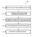
- FIG. 4 is a flowchart illustrating one embodiment of a method of wireless device discovery in a communication network wherein the wireless devices employ directional antennas.
- FIG. 5 is a flowchart illustrating another embodiment of a method of wireless device discovery in a communication network wherein the wireless devices employ directional antennas.
- FIG. 1 is a functional block diagram of a wireless device 100 .
- one or more of the various “parts” shown in FIG. 1 may be physically implemented using a software-controlled microprocessor, hard-wired logic circuits, or a combination thereof. Also, while the parts are functionally segregated in FIG. 1 for explanation purposes, they may be combined variously in any physical implementation.
- Wireless device 100 includes a transceiver 110 , processor 120 , memory 130 , and a directional antenna system 140 .
- Transceiver 110 includes a receiver 112 and a transmitter 114 , and provides functionality for wireless device 100 to communicate with other wireless devices in a wireless communication network according to the standard protocols of the wireless communication network.
- wireless device 100 may be a UWB wireless device adapted to operate using a communication protocol according to the WiMedia specifications.
- Processor 120 is configured to execute one or more software algorithms in conjunction with memory 130 to provide the functionality of wireless device 100 .
- processor 120 includes its own memory (e.g., nonvolatile memory) for storing executable software code that allows it to perform the various functions of wireless device 100 .
- the executable code may be stored in designated memory locations within memory 130 .
- antenna system 140 includes an omnidirectional antenna pattern capability and a directional antenna pattern capability.
- the directional and omnidirectional capabilities may be provided by some or all of the same components. In another embodiment, these capabilities may be provided by an omnidirectional antenna component and a separate directional antenna component.
- the directional antenna component provides a capability for wireless device 100 to select from a plurality of antenna beams for communicating with other wireless devices in a plurality of directions.
- antenna system 140 comprises a plurality of antennas each corresponding to one antenna beam.
- the directional antenna system component comprises a steerable antenna that can combine a plurality of different antenna elements to form and steer a beam in a desired one of a plurality of different directions.
- wireless communication network when a wireless communication network operates with wireless devices 100 that employ directional antenna patterns, some mechanism must be employed to allow the wireless devices to “discover” and locate each other so that they can direct their antennas towards each other and establish a communication link.
- One important solution to this problem is to employ omnidirectional antenna patterns during an initial “device discovery phase,” when a wireless device determines where other wireless devices with which it desires to communicate are located, and then once device discovery is complete to switch back to the directional antenna patterns during the subsequent “normal” communication phase.
- FIG. 2 illustrates a communication network 200 including wireless devices 210 A, 210 B, etc. employing omnidirectional antenna patterns 202 and directional antenna patterns 204 .
- all of the wireless devices 210 A, 210 B, 210 C and 210 D can communicate with each other using directional antenna patterns 204 .
- wireless devices 210 A and 210 B which are closely located to each other may communicate using omnidirectional antenna patterns 202 .
- wireless devices 210 C and 210 D which are closely located to each other also may communicate using omnidirectional antenna patterns 202 .
- wireless device 210 A is unable to communicate with remotely located wireless device 210 D using omnidirectional antenna pattern 202 . So it is seen that two wireless devices may not be able to communicate with each other using omnidirectional antenna patterns 202 , even though they could communicate with each other using directional antenna patterns 204 . For example, if wireless devices 210 operate with an antenna gain of 10 dBi gain using directional antenna patterns 204 during “normal” communications, then there will be a total of 20 dB (both sides included) of signal gain that must be recovered somehow during the discovery mode when omnidirectional antenna patterns 202 are employed.
- data may be communicated during the wireless device discovery phase with significant redundancy so that the gain of the directional antenna pattern 204 which is lost due to omnidirectional operation can be recovered from the transmitted redundancy. For example, to compensate for the absence of 20 dB of antenna gain (transmit and receive antennas), the data would need to be spread (or repeated) by a factor of approximately 100.
- a typical wireless communication system packet structure includes a predetermined preamble, which is transmitted first, followed by transmission of the remainder of the packet including channel estimation, header, and payload data.
- the predetermined preamble sequence is known a priori by the receiver at a receiving wireless device, so the receiver may correlate a received signal with the known preamble sequence to synchronize the timing of the receiver to the transmitted signal.
- spreading the preamble sequence would require a severe increase in the complexity of a correlator that is used at the wireless receiver for synchronization.
- the original segment of a preamble sequence consists of 256 samples
- spreading the preamble by 100 times requires 25,600 delay elements at the receiver for correlation. This is impractical and effectively precludes the use of spreading for transmitting the preamble sequence.
- the remainder of the packet can be spread by a factor of 100, as its detection only requires a length—100 despreader at the receiver.
- a wireless device transmits the preamble sequence differently than the remainder of the packet so as to repeat/spread the preamble sequence in one manner and the remainder of the packet in a different manner.
- the preamble sequence may be transmitted using only a narrowband (NB) portion of a communication channel, and the remainder of the packet may be transmitted using the full wideband (WB) bandwidth of the communication channel.
- NB narrowband
- WB full wideband
- the receiver operates in a smaller portion of the channel with a reduced bandwidth when detecting the preamble sequence, compared to detecting an equivalent wideband signal which occupies the entire channel, the preamble sequence may be detected with a reduced signal level, thus compensating in whole or in part for the reduced signal level received during omnidirectional operation.
- a wireless device transmitting a packet repeats transmission of each sample of a known synchronization sequence N times.
- y WB (n) is the original “wideband” predetermined synchronization sequence
- M is the length of the synchronization sequence
- y NB (n) is the resulting transmitted “narrowband” preamble sequence.
- BW 1 BW 2 /N (2)
- the transmitter 114 in a wireless device 110 may employ a sample-and-hold unit to produce the narrowband preamble y NB (n), with the spectrum being shaped by the spectrum of a sample-and-hold unit.
- N can be set equal to 100.
- the bandwidth of the communication channel that is used during normal data communication phase with the directional antenna patterns is defined as BW 2
- BW 1 of the narrowband (NB) signal can be set to be BW 2 /100.
- the wireless device transmits a “full bandwidth” wideband (WB) signal for the remainder of the packet, including the header and payload data.
- WB wideband
- the remainder of the packet following the narrowband preamble sequence y NB (n) can be made to fill all of nearly all of the bandwidth of the communication channel.
- this also improves the multi-path fading immunity of the transmission.
- the length of the spreading sequence, P is selected to be the same as the number of times, N, that each sample in the narrowband preamble sequence is repeated.
- FIG. 3 illustrates one embodiment of a structure of a discovery mode packet 300 , and corresponding frequency domain representation of the signals associated with various portions of packet 300 , that is transmitted by a wireless device using an omnidirectional antenna during a wireless device discovery process.
- Packet 300 includes a narrowband preamble 310 , which is followed by a remainder 320 of packet 300 .
- the remainder 320 of packet 300 includes an optional wideband preamble 322 (which may be omitted), a wideband header 324 , and a wideband payload portion (i.e., payload data) 326 .
- a quiet period 315 may be inserted between the narrowband preamble 310 and the remainder 320 of packet 300 .
- narrowband preamble 310 comprises the preamble sequence y NB (n) transmitted with a first, narrowband, bandwidth 302 (BW NB ), while the remainder 320 of packet 300 comprises the header and payload data that is spread to occupy a much wider bandwidth 304 (BW WB ).
- the remainder 320 of packet 300 is transmitted using a spreading sequence which spreads the data contained therein with a spreading sequence of length P to compensate for some or all of the gain lost by switching from a directional antenna pattern that is used during normal transmission to the omnidirectional antenna pattern used in the wireless device discovery process.
- the entire preamble 310 is transmitted in a small portion of the channel, and so is more susceptible to multipath fading than the remainder 320 of packet 300 which occupies a much wider bandwidth.
- a frequency-shifted combination of the preamble sequence may be transmitted to result in a multi-frequency (multi-band) preamble.
- the preamble sequence may be:
- f k is the frequency shift
- T is the sampling interval.
- the frequency shift can be implemented in the analog domain.
- the frequency shift is affected by a frequency hopping scheme. Such a multi-frequency preamble may improve performance when the communication channel exhibits frequency-selective deep fading over a relatively narrow bandwidth.
- FIG. 4 is a flowchart illustrating one embodiment of a method 400 of wireless device discovery in a communication network wherein the wireless devices employ directional antenna patterns for normal data communication, and employ omnidirectional antenna patterns during wireless device discovery.
- FIG. 4 illustrates operations at a transmitter 114 of a wireless device 100 during one embodiment of wireless device discovery process, and a data communication.
- a wireless device 100 places itself into a device discovery mode. In that case, it controls antenna system 140 to produce an omnidirectional antenna pattern 202 .
- wireless device 100 configures transmitter 114 to transmit a packet preamble sequence 320 of a first (data discovery) packet 300 by repeating each sample of a synchronization sequence N times (N>1).
- wireless device 100 configures transmitter 114 to transmit a remainder of the first packet 300 by spreading each sample thereof with a spreading factor P (P>1).
- a transmitting wireless device 100 employing an omnidirectional antenna pattern 202 can transmit a data discovery packet 300 to a receiving wireless device 100 also employing an omnidirectional antenna pattern 202 to execute a wireless device discovery phase of communication.
- the wireless device 100 places itself into a data communication mode. In that case, it controls antenna system 140 to produce a directional antenna pattern 204 .
- wireless device 100 transmits a normal data packet using the directional antenna pattern 204 .
- FIG. 5 is a flowchart illustrating another embodiment of a method 500 of wireless device discovery in a communication network wherein the wireless devices employ directional antenna patterns for normal data communication, and employ omnidirectional antenna patterns during wireless device discovery.
- FIG. 5 illustrates operations at a receiver 112 of a wireless device 100 during one embodiment of wireless device discovery process, and a data communication.
- a wireless device 100 places itself into a device discovery mode. In that case, it controls antenna system 140 to produce an omnidirectional antenna pattern 202 .
- wireless device 100 configures receiver 112 to detect a narrowband preamble sequence, y NB (n) which has been generated from a predetermined “wideband” synchronization sequence y WB (n) of a first (discovery mode) packet 300 .
- receiver 112 of wireless device 100 scans the communication channel until the synchronization sequence y WB (n) is detected or a timeout occurs. In this step, receiver 112 performs narrow-band processing until the synchronization sequence y WB (n) is detected. In one embodiment, receiver 112 performs matched filtering and sampling on the preamble sequence y NB (n), followed by correlation and detection of the synchronization sequence y WB (n). The correlation and detection of the synchronization sequence y WB (n) is performed at a low bandwidth/speed, thereby eliminating the need to have a large number of delay elements in the correlator of receiver 112 .
- wireless device 100 synchronizes its operations to the transmitted signal, using the synchronization sequence, and then changes the configuration of receiver 112 to demodulate the remainder 320 of the packet 300 , which has been transmitted using a spreading sequence of length P to spread the signal over a wideband (WB) spectrum.
- WB wideband
- the transmitter 114 of the wireless device 100 which transmitted the packet 300 may have inserted an optional quiet period 315 in the packet 300 that is known to the receiver 112 . In that case, the receiving wireless device 100 can use this quiet period to reconfigure its receiver 112 and/or processor 120 to operate in the wideband mode.
- receiver 112 can then de-spread, demodulate and decode the full-bandwidth header and payload data accordingly.
- the header and/or payload data includes information that allows the receiving wireless device to discover the presence of the transmitting wireless device. This may include data identifying the particular transmitting wireless device and/or the location or direction of the transmitting wireless device. If an optional full-bandwidth preamble 320 is transmitted, then receiver 112 can use this sequence 320 to readjust adjust some receiver parameters, such as gain setting, frequency and timing error calculation, and channel estimation.
- a receiving wireless device 100 employing an omnidirectional antenna pattern 202 can receive a data discovery packet 300 from a transmitting wireless device 100 also employing an omnidirectional antenna pattern 202 to execute a wireless device discovery phase of communication.
- the wireless device 100 places itself into a data communication mode. In that case, it controls antenna system 140 to produce a directional antenna pattern 204 .
- wireless device 100 receives a normal data packet using the directional antenna pattern 204 .
- the whole preamble sequence y NB (n) itself can be repeated K times to increase the chance of correct synchronization.
- a cover sequence may be used when y NB (n) is repeated for several purposes, one of which is a frame delimiter.
- the repeating methodology described in the embodiment above to produce y NB (n) is a simple sample-and-hold approach with its corresponding characteristics. However in another embodiment, a different methodology may be used with different frequency characteristics.
- a different mechanism may be employed to spread the data, such as addition of extra error correction bits, or a combination of spreading and additional error correction bits.
- error correction conventional coding techniques such as convolution coding, trellis coding, Reed-Solomon and LDPC coding can be employed.
Landscapes
- Engineering & Computer Science (AREA)
- Computer Networks & Wireless Communication (AREA)
- Signal Processing (AREA)
- Databases & Information Systems (AREA)
- Mobile Radio Communication Systems (AREA)
Abstract
Description
y NB(n)=y WB(floor(n/N)), n=0,1, . . . ,(N*M−1). (1)
where yWB(n) is the original “wideband” predetermined synchronization sequence, M is the length of the synchronization sequence yWB(n), and yNB(n) is the resulting transmitted “narrowband” preamble sequence. If BW1 is the resulting bandwidth of the transmitted preamble sequence yNB(n), and BW2 is the bandwidth that would be employed for transmitting the original “wideband” synchronization sequence yWB(n), then:
BW 1 =BW 2 /N (2)
The
x WB(n)=x(floor(n/P))×v(mod(n,P)) (3)
where x(n) is the original low-rate header and payload data sequence, v(n) is a length-P spreading sequence, and xWB(n) is the full bandwidth spread sequence. With a careful choice for v(n), the remainder of the packet following the narrowband preamble sequence yNB(n) can be made to fill all of nearly all of the bandwidth of the communication channel. Beneficially, in addition to providing processing gain for overcoming gain lost when switching from a directional to an omnidirectional antenna pattern, this also improves the multi-path fading immunity of the transmission.
where fk is the frequency shift, and T is the sampling interval. In one embodiment, the frequency shift can be implemented in the analog domain. In one embodiment, the frequency shift is affected by a frequency hopping scheme. Such a multi-frequency preamble may improve performance when the communication channel exhibits frequency-selective deep fading over a relatively narrow bandwidth.
Claims (12)
Priority Applications (1)
| Application Number | Priority Date | Filing Date | Title |
|---|---|---|---|
| US12/746,569 US9338632B2 (en) | 2008-01-09 | 2008-12-18 | Method and system of wireless device discovery in a wireless network employing directional antennas |
Applications Claiming Priority (3)
| Application Number | Priority Date | Filing Date | Title |
|---|---|---|---|
| US2001608P | 2008-01-09 | 2008-01-09 | |
| PCT/IB2008/055434 WO2009087521A1 (en) | 2008-01-09 | 2008-12-18 | Method and system of wireless device discovery in a wireless network employing directional antennas |
| US12/746,569 US9338632B2 (en) | 2008-01-09 | 2008-12-18 | Method and system of wireless device discovery in a wireless network employing directional antennas |
Publications (2)
| Publication Number | Publication Date |
|---|---|
| US20100265990A1 US20100265990A1 (en) | 2010-10-21 |
| US9338632B2 true US9338632B2 (en) | 2016-05-10 |
Family
ID=40578824
Family Applications (1)
| Application Number | Title | Priority Date | Filing Date |
|---|---|---|---|
| US12/746,569 Active 2032-04-05 US9338632B2 (en) | 2008-01-09 | 2008-12-18 | Method and system of wireless device discovery in a wireless network employing directional antennas |
Country Status (6)
| Country | Link |
|---|---|
| US (1) | US9338632B2 (en) |
| EP (1) | EP2241137B1 (en) |
| JP (1) | JP5244197B2 (en) |
| KR (1) | KR101449402B1 (en) |
| CN (1) | CN101911780B (en) |
| WO (1) | WO2009087521A1 (en) |
Families Citing this family (10)
| Publication number | Priority date | Publication date | Assignee | Title |
|---|---|---|---|---|
| US8255714B2 (en) * | 2008-07-17 | 2012-08-28 | Samsung Electronics Co., Ltd. | System and method for establishing a direct link on the high throughput channel of a multi-rate channel wireless communications network |
| US9007968B2 (en) * | 2009-06-16 | 2015-04-14 | Samsung Electronics Co., Ltd. | System and method for wireless multi-band networks association and maintenance |
| US8638833B1 (en) * | 2009-07-30 | 2014-01-28 | Qualcomm Incorporated | Method and apparatus for physical layer control communications in a wireless communications protocol |
| US8400955B2 (en) * | 2009-09-21 | 2013-03-19 | Samsung Electronics Co., Ltd. | System and method for power saving by coordinated wake-up in a wireless multi-band network |
| WO2011044950A1 (en) * | 2009-10-16 | 2011-04-21 | Hewlett-Packard Development Company, L.P. | Identifying a device |
| US9247567B2 (en) * | 2009-11-20 | 2016-01-26 | Qualcomm Incorporated | Methods and apparatus for providing silence periods in directional communications networks |
| US8989732B2 (en) | 2012-01-30 | 2015-03-24 | Electronics And Telecommunications Research Institute | Method and apparatus for setting communication target in wireless communication system |
| WO2017050389A1 (en) * | 2015-09-25 | 2017-03-30 | Huawei Technologies Co., Ltd. | Communication protocol for low energy communication links |
| US11641627B2 (en) * | 2019-08-02 | 2023-05-02 | Qualcomm Incorporated | Power control indication in groupcast sidelink communications |
| CN113993117B (en) * | 2021-10-27 | 2024-02-23 | 武汉船舶通信研究所(中国船舶重工集团公司第七二二研究所) | Communication node connection method based on omni-directional antenna and directional antenna |
Citations (6)
| Publication number | Priority date | Publication date | Assignee | Title |
|---|---|---|---|---|
| US20030048770A1 (en) * | 2001-09-13 | 2003-03-13 | Tantivy Communications, Inc. | Method of detection of signals using an adaptive antenna in a peer-to-peer network |
| US20030086366A1 (en) * | 2001-03-06 | 2003-05-08 | Branlund Dale A. | Adaptive communications methods for multiple user packet radio wireless networks |
| US20060159058A1 (en) * | 2005-01-18 | 2006-07-20 | Freescale Semiconductor Inc. | Dual stage automatic gain control in an ultra wideband receiver |
| US20070248195A1 (en) * | 2006-04-25 | 2007-10-25 | Texas Instruments Incorporated | Apparatus for and method of robust packet detection and frequency offset estimation |
| US20080080472A1 (en) * | 2006-10-03 | 2008-04-03 | Pierre Bertrand | Efficient Scheduling Request Channel for Wireless Networks |
| US20090125792A1 (en) * | 2007-11-06 | 2009-05-14 | Qualcomm Incorporated | Method and apparatus for preamble creation and communication in a wireless communication network |
Family Cites Families (5)
| Publication number | Priority date | Publication date | Assignee | Title |
|---|---|---|---|---|
| FR2598250B1 (en) * | 1986-04-30 | 1988-07-08 | Thomson Csf | RADIOLOGICAL PICTURE PANEL, AND MANUFACTURING METHOD |
| FR2627924B1 (en) * | 1988-02-26 | 1990-06-22 | Thomson Csf | PHOTOSENSITIVE DEVICE AND IMAGE DETECTOR COMPRISING SUCH A DEVICE, PARTICULARLY A DOUBLE ENERGY IMAGE DETECTOR |
| US7826431B2 (en) * | 2004-05-14 | 2010-11-02 | Interdigital Technology Corporation | Method of selectively adjusting the configuration of an access point antenna to enhance mobile station coverage |
| US7613138B2 (en) * | 2005-05-23 | 2009-11-03 | Microsoft Corporation | Separating control and data in wireless networks |
| JPWO2007091650A1 (en) * | 2006-02-10 | 2009-07-02 | パナソニック株式会社 | Wireless communication system |
-
2008
- 2008-12-18 JP JP2010541856A patent/JP5244197B2/en active Active
- 2008-12-18 KR KR1020107017520A patent/KR101449402B1/en active Active
- 2008-12-18 US US12/746,569 patent/US9338632B2/en active Active
- 2008-12-18 EP EP08870534A patent/EP2241137B1/en active Active
- 2008-12-18 CN CN200880124464.6A patent/CN101911780B/en active Active
- 2008-12-18 WO PCT/IB2008/055434 patent/WO2009087521A1/en active Application Filing
Patent Citations (7)
| Publication number | Priority date | Publication date | Assignee | Title |
|---|---|---|---|---|
| US20030086366A1 (en) * | 2001-03-06 | 2003-05-08 | Branlund Dale A. | Adaptive communications methods for multiple user packet radio wireless networks |
| US20030048770A1 (en) * | 2001-09-13 | 2003-03-13 | Tantivy Communications, Inc. | Method of detection of signals using an adaptive antenna in a peer-to-peer network |
| WO2003023895A2 (en) | 2001-09-13 | 2003-03-20 | Interdigital Acquisition Corporation | Method of detection of signals using an adaptive antenna in a peer-to-peer network |
| US20060159058A1 (en) * | 2005-01-18 | 2006-07-20 | Freescale Semiconductor Inc. | Dual stage automatic gain control in an ultra wideband receiver |
| US20070248195A1 (en) * | 2006-04-25 | 2007-10-25 | Texas Instruments Incorporated | Apparatus for and method of robust packet detection and frequency offset estimation |
| US20080080472A1 (en) * | 2006-10-03 | 2008-04-03 | Pierre Bertrand | Efficient Scheduling Request Channel for Wireless Networks |
| US20090125792A1 (en) * | 2007-11-06 | 2009-05-14 | Qualcomm Incorporated | Method and apparatus for preamble creation and communication in a wireless communication network |
Non-Patent Citations (3)
| Title |
|---|
| Kalis A et al: "Relative Direction Determination in Mobile Computing Networks" IMTC 2001. Proceedings of the 18th. IEEE Instrumentation and Measurement Technology Conference. Budapest, Hungary, May 21-23, 2001; [IEEE Instrumentation and Measurement Technology Conference. (IMTC):], New York, NY : IEEE, US, vol. 3, May 21, 2001, pp. 1479-1484, XP010547207. |
| Maxim Piz et al: "A Synchronization Scheme for OFDM-based 60 GHZ WPANS" IEEE International Symposium on Personal, Indoor and Mobile Radio Communications. PIMRC, IEEE; PI, XX, Sep. 1, 2007, pp. 1-5, XP031168162. |
| Toufik I et al "Multiuser Channel Allocation Algorithms Achieving Hard Fairness" Global Telecommunications Conference, 2004. Globecom '04. IEEE Dallas, TX, USA, Nov. 29-Dec. 3, 2004, Piscataway, NJ, USA,IEEE, vol. 1, Nov. 29, 2004, pp. 146-150, XP010758870. |
Also Published As
| Publication number | Publication date |
|---|---|
| JP5244197B2 (en) | 2013-07-24 |
| KR101449402B1 (en) | 2014-10-15 |
| US20100265990A1 (en) | 2010-10-21 |
| CN101911780A (en) | 2010-12-08 |
| EP2241137A1 (en) | 2010-10-20 |
| EP2241137B1 (en) | 2012-10-31 |
| JP2011509618A (en) | 2011-03-24 |
| KR20100103864A (en) | 2010-09-28 |
| WO2009087521A1 (en) | 2009-07-16 |
| CN101911780B (en) | 2014-08-13 |
Similar Documents
| Publication | Publication Date | Title |
|---|---|---|
| US9338632B2 (en) | Method and system of wireless device discovery in a wireless network employing directional antennas | |
| US11552673B2 (en) | Node having an adaptive space-spectrum whitener and multi-user rake receiver for use in a cooperative broadcast multi-hop network that employs broadcast flood routing and multi-hop transmission with cooperative beamforming and adaptive space-spectrum whitening | |
| US8509724B2 (en) | Switched beam antenna with digitally controlled weighted radio frequency combining | |
| EP0960544B1 (en) | Method and apparatus for directional radio communication | |
| AU725331B2 (en) | Method and apparatus for directional radio communication | |
| AU725235B2 (en) | Method and apparatus for directional radio communication | |
| US6392595B1 (en) | Method and apparatus for directional radio communication | |
| Han et al. | MA-ADM: A memory-assisted angular-division-multiplexing MAC protocol in Terahertz communication networks | |
| EP0965239A1 (en) | Method and apparatus for directional radio communication | |
| JPH1028107A (en) | Method for selecting receiving antenna and diversity receiver | |
| US6799026B1 (en) | Handset diversity in wireless communications system | |
| US8615203B2 (en) | Antenna selection | |
| CN111567120A (en) | Spectrum management for point-to-multipoint wireless networks | |
| KR20180010047A (en) | Apparatus and method receiving signal using single RF chain | |
| US8451934B1 (en) | Method and system for increasing throughput of a wireless channel using multipath transmission | |
| WO2022234007A1 (en) | Coverage enhancing devices providing ofdm symbol delays | |
| JP4916134B2 (en) | COMMUNICATION DEVICE AND ITS CONTROL METHOD | |
| Prasad et al. | Packet-switched hybrid DS/SFH CDMA network with B-, Q-and D-PSK modulation in an indoor Rician fading environment | |
| Mui | A simulcast UHF terrestrial radio network |
Legal Events
| Date | Code | Title | Description |
|---|---|---|---|
| AS | Assignment |
Owner name: KONINKLIJKE PHILIPS ELECTRONICS N.V., NETHERLANDS Free format text: ASSIGNMENT OF ASSIGNORS INTEREST;ASSIGNOR:BIRRU, DAGNACHEW;REEL/FRAME:024493/0102 Effective date: 20090202 |
|
| STCF | Information on status: patent grant |
Free format text: PATENTED CASE |
|
| MAFP | Maintenance fee payment |
Free format text: PAYMENT OF MAINTENANCE FEE, 4TH YEAR, LARGE ENTITY (ORIGINAL EVENT CODE: M1551); ENTITY STATUS OF PATENT OWNER: LARGE ENTITY Year of fee payment: 4 |
|
| MAFP | Maintenance fee payment |
Free format text: PAYMENT OF MAINTENANCE FEE, 8TH YEAR, LARGE ENTITY (ORIGINAL EVENT CODE: M1552); ENTITY STATUS OF PATENT OWNER: LARGE ENTITY Year of fee payment: 8 |