US933262A - Stamp-affixing machine. - Google Patents
Stamp-affixing machine. Download PDFInfo
- Publication number
- US933262A US933262A US33399706A US1906333997A US933262A US 933262 A US933262 A US 933262A US 33399706 A US33399706 A US 33399706A US 1906333997 A US1906333997 A US 1906333997A US 933262 A US933262 A US 933262A
- Authority
- US
- United States
- Prior art keywords
- carriage
- stamp
- stamps
- sheet
- row
- Prior art date
- Legal status (The legal status is an assumption and is not a legal conclusion. Google has not performed a legal analysis and makes no representation as to the accuracy of the status listed.)
- Expired - Lifetime
Links
Images
Classifications
-
- B—PERFORMING OPERATIONS; TRANSPORTING
- B21—MECHANICAL METAL-WORKING WITHOUT ESSENTIALLY REMOVING MATERIAL; PUNCHING METAL
- B21D—WORKING OR PROCESSING OF SHEET METAL OR METAL TUBES, RODS OR PROFILES WITHOUT ESSENTIALLY REMOVING MATERIAL; PUNCHING METAL
- B21D51/00—Making hollow objects
- B21D51/16—Making hollow objects characterised by the use of the objects
- B21D51/38—Making inlet or outlet arrangements of cans, tins, baths, bottles, or other vessels; Making can ends; Making closures
- B21D51/44—Making closures, e.g. caps
-
- B—PERFORMING OPERATIONS; TRANSPORTING
- B65—CONVEYING; PACKING; STORING; HANDLING THIN OR FILAMENTARY MATERIAL
- B65C—LABELLING OR TAGGING MACHINES, APPARATUS, OR PROCESSES
- B65C1/00—Labelling flat essentially-rigid surfaces
- B65C1/02—Affixing labels to one flat surface of articles, e.g. of packages, of flat bands
-
- Y—GENERAL TAGGING OF NEW TECHNOLOGICAL DEVELOPMENTS; GENERAL TAGGING OF CROSS-SECTIONAL TECHNOLOGIES SPANNING OVER SEVERAL SECTIONS OF THE IPC; TECHNICAL SUBJECTS COVERED BY FORMER USPC CROSS-REFERENCE ART COLLECTIONS [XRACs] AND DIGESTS
- Y10—TECHNICAL SUBJECTS COVERED BY FORMER USPC
- Y10T—TECHNICAL SUBJECTS COVERED BY FORMER US CLASSIFICATION
- Y10T156/00—Adhesive bonding and miscellaneous chemical manufacture
- Y10T156/12—Surface bonding means and/or assembly means with cutting, punching, piercing, severing or tearing
- Y10T156/137—Stamp from multiple row sheet type
Definitions
- My invention relates to stamp-aflixing machines, and more particularly to that class of machines in which "the stamps are successivel,y fed under a plunger, successively moistened, and separated from the sheet of stamps and affixed to the face of envelops.
- the object of my invention is to produce a machine in which all of, the operations incident to the-affixing of an entire sheet of stamps will be performed, directly and indirectly, bythe reciprocation of a single lever.
- a sheet of stamps is placed in the machine, flat upon a bed-plate; .it is brought to place so that the first stamp ofthe first row has been moistened and is in registry with the atfixing plunger.
- a stroke of the hand lever acts to sever the stamp from the sheet and to affix it.
- the automatic return of the hand lever moves the sheet of stamps forward, step. by step, and, step by step, sets up, and finally actuates mechanism which shifts the sheet of stamps back and brings the next row to be aifixed in line and in registry, and repeats such operations until all of the sheet has been affixed.
- the several functions performed are,.- (1) moving the stamp to position; (2) moist'ening the stamp; (3) severing the stamp from the. sheet and a-flixing the same; (4) disengaging the carriers from the sheet of stamps; (5) moving the carriage to engage another row of stamps;' (6) carrying the sheet of stamps back to the beginning or right hand end of, the machine; ing the sheet forward to the line tion: (8) bringing th'e'first stamp to position of registry.
- Figures 1 and 2 taken together constitute a 4 taken together constitute a front elevation;
- Fig. 5 is a section on the line wm of Fig. 2;
- Fig. 6 is a detail perspective of the mechanism for bringing the first stamp of a row'to position of registry;
- Fig. 7 is a detail perspective of my means for raising the carria e clear of the sheet of stamps.
- the bed obstructed surface slightly wider than a sheet of stamps and slightly more than twice the length of transverse waysat the ends of the bed 1 is a bridge 2, made up of end pieces and four longitudinal bars 2, 2', and 2".
- a carriage 3 is mounted to travel longitudinally upon the bridge 2. Y It will thus be seen that the carriage moves, with reference to the bed 1, in all four directions-longitudinally upon the bridge 2, and transversely with the bridge 2.
- a serrated blade 4 (see Fig. 3) the'serrations of which bear against the face of the sheet of stamps to carry it along on the bed 1 I also secure spring fingers 5 to the carriage to further grip and carry the sheet of stamps.
- a rectangularshaped yoke 21 Secured to the upper ends of the rods 17 is a rectangularshaped yoke 21, and interposed between the yoke 21 and the upper surface of the plate 7 and over the guide rods 19 are springs 22, which tend to raise the yoke 21 and the prcsser 20.
- a guide casing 22 rectangular in cross section and having an interior cross sectionequal to that of the opening 17.
- the stamp plunger F23 Within this casing 22 is the stamp plunger F23. which has the same cross section as the opening 1.7, and is, of
- the stamp plunger 23 1s link-pivoted to the hand lever 15. Secured to the hand lever 6 is a yoke :24, and to the yoke 24 are secured rods 25 which, at their hiwer ends pass through the yoke 21 and are free to reciprocate therein. Over these rods are placed springs 26 which tend to force the yokes apart. The springs 26 are considerably stronger than the springs 22, for reasons which will appear presently. The operation is as follows: Assuming a stamp to be in placeover the opening 17, when pressure is applied to the hand lever 6-the springs 26 being unitedly stronger than the springs 22 nnitedlythe presser 20 will be forced down upon the sheet of stamps and will hold the sheet firmly.
- the plunger 23 will then be forced down, and entering the opening 17 will sever and carry down the stamp to beafiixed upon an envelop previously placed beneath the opening 17 As soon as pres sure is removed from the hand lever 6 the parts will return to normal. position. It will also be noted that, in this movement, the dogs 11 and 13 have coiipcrated with the rack 9, as described in the second preceding operation, and moved the carriage one step,
- the carriage 3 is provided with a longitudinal bar 63 which is suitably mounted on the transverse bars 6% and 65 and is preferably raised somewhat above the level of the carriage.
- the bar 63 is adapted to register with and travel through grooves 66 and 67 in the lower part of the transverse fixed plate 7, and these,
- grooves are spaced-apart the width of a single row of stamps.
- the bar 63 is provided with indentations 68 and 69 which are spaced apart a distance equal to the distance between the cross pieces51 and 54..
- the carriage 3 Upon the carriage 3 are the flat bars 27, arranged at the four corners of the carriage. Pivoted to the bed 1 are lever arms 28, underneath which are compression springs 29 (see F '7) and over the free ends of which are slotthe carriage cannot rise, as it is held down by the lugs mmediately.
- the bridge 2 is provided with stops and 71 and when it is movedtransversely back- Wardly the stops 70 strike against the raised of the bed plate 1; when it is moved transversely forwardly the strike against the raised side, bar 73 of the bed plate 1.
- the transverse movements of the bridge 2 are limited to the Width of a row of stamps.
- the ends of the plates 27 drop 0E from the-lever arms 28 and allow the serrated blade 4 and the spring fingers 5 to engage the sheet of stamps. .f
- Brinyin i716 sheet of stamps forward.Mounted to reciprocate upon the fixed plate 7 (see Figs. 2 and is a rack 42.
- a guide rod 43 connects the rack 42 with the bracket 6, and interposed between the bracket 6 and the rack 42 and placed over the guided-0d 43 is a compression spring 44.
- a dog 45 capable of engaging the rack 42 is pivoted to a bell-crank lever 46 which is piv oted to a bracket on the fixed plate 7, and this bell-cjrank lever 46 is, in turn, connected to the hand lever 6 by pivot-links.
- a lug 47' Upon the under side of the plate 7' is a lug 47' (see Fig. 5) which is connected to and moves with the rack 42. This lug 47 is so positioned as to engage a bar of the "carriage 3 as presently described.
- a dog 49 secured to the plate 7 engages the rack 48.
- the operation is as follows; ⁇ Vith each movementof the hand lever 6, the dog 45 moves the rack 42 one notch, the dog 49 engaging the rack 48 to prevent the rack 42 from moving back.
- the spring 44 is set up and the) lug 47 moved
- Aflat bar 50 has one end secured to a cross-piece 51 secured to the base of the machine (see Figs. 1 and. 2) and has the other, free and lying underneath the dog49.
- a downwardly projecting lug 52 shown in dotted outline in Fig.
- On the carriage see Fig. 1
- a lug 53 is a lug 53.
- the operation is as follows: The spring 44 having been set up and the lug 47 having been moved back by the action of the dog 45 in the rack 42, when the carriage is moved over transversely as above described in the 5th movement, the lug will be under the bar 50; and as the carriage reaches its initial position at the right hand end, the lug 53 will strike the lug '52 on the underside of the bar 50, and as the lug 52 is beveled upwardly to slide over the lug 53, it will cause the bar 50 to be raised and to lift the dog 49 out of engagement with the rack 48.
- the do 57 is of s r111 material and ields 1 upwardly to pass over the teeth of the rack 58. It is also capable of moving horizontally in one direction on its pivot, but is held normally over the rack by a spring 59.
- the dog has at its fore end a downwardly and backwardly bent extension 57 as clearly shown in Fig. 6.
- a lug 60 with a hooked end Upon the carriage (see Figs. 1 and is a lug 60 with a hooked end, which is capable of engaging the extension 57 on the dog 5?, as hereafter de scribed. Slot-pivoted to the common plate of racks l2 and st?
- a bell-crank lever 61 which reciprocates on a pivot on the crosspiece 5 1-, and the other end of which engages a pin 62 on the sliding plate 55. It will now be seen that, as-the racks 42 and 48 are moved back, the bell-crank lever 61 will be moved, and that it, in turn, bearing against the pin 62, will move the sliding plate 55 and cause the dog 57 to engage in an advance-notch in the rack .58 With each step. Thus, as the hand lever is reciprocated in the process of affixing a row of stamps, the spring 56 is set up and the plate moves to the right.
- the lug 60 engages the hooked or bent end 57 of the dog 57 and throws the dog sidewise, against the spring 59, out of the rack 58. This allows the spring 56 toact, through the engagement of the dog 57 with the lug 60 upon the carriage and to draw the same forward (to the left) until the limits of the slots in the plate 55 are reached, which is the predetermined position of registry for the sheet of stamps.
- a stamp affixing machine means for severing and aflixing a stamp, means for bringing the next stamp to position for affixing, means for moving a sheet of stamps after one row has been aflixed, means for bringing another row of stamps into line for afiixing, and n'leans for bringing the first stamp of a row to registry for afli'xing by an auto inatic initial forward movement.
- means for moistening, severing and aflixing a stamp means for bringing the next stamp to position for aiiixing, means for moving a sheet of stamps after one row has been affixed, means for bringing another row of stamps into line for afiixing, and means for bringing the first stamp of a row to registry for aflixing by an automatic initial forward movement.
- a stamp affixing machine means for moistening a stamp, means for severing and aflixing the stamp by the reciprocation of a lever, means for automatically bringing the next stamp to position for allixing by the action of said lever in afiixing the first stamp, and means for auton'iatically bringing the first stamp of the next row on a sheet to place for aflixmg by automatically moving the sheet of stamps back, then transversely, and then forward to bring the first stamp of the next row to position for afiixing: when one row has been dlfiXGd.
- a stamp aflixing machine means for moistening, severing and aflixing a stamp, means for moving a sheet of stamps step by step .for successively aflixing all the stamps of one row, means for automatically moving the sheet back, transversely, and then for ward bringing the first stamp of the next row into position for afiixing and means for thus automatically bringing the several rows into position one row at a time for afiixing one stamp at a time until the entire sheet has been aflixed.
- a bed for receiving a sheet of stamps flat, a moistening device, a reciprocating device for severing and affixing a stamp, means actuated by said reciprocating device for moving the sheet of stamps on said bed step by step for affixing, and means actuated by said reciprocating device for moving said sheet of stamps longitudinally and transversely to bring the next row of stamps in position for aliixing.
- a bed for receiving a sheet of stamps fiat, a moistening device, a reciprocating device for severing and affixing a stamp, a carriage and means for gripping a sheet of stamps and automatic means actuatedby said reciprolating device for moving said carriage step by step, for releasing saidgripping means when a row of stamps has been afiixed, for moving said carriage transversely to engage the sheet of stamps to bring another row to place, for
- a stamp aflixin'g machine for receiving a sheet of stamps flat, a reciproeating device for severing and affixing a stamp, a carriage, means for locking said carriage'a aiiisttransverse movement while a rowof 5 amps is being afiixed, means for gripping the sheet of stamps, means actuated by said reciprocating device for moving said carriage step by step so as to bring success ve stamps of the row into position for aflixing, means for releasing said gripping means when a row of stamps has been affixed, means for releasing said carriage and allowing it to move transversely so ja's to engage the sheet of stamps and bring another row to place, meaiis for moving said carriage and the sheet of stamps back, and means for moving said carriagetransversely to bring the next row into position for affixing.
- a bed for receiving a sheet of stamps flat, a moistening device, a reciprocating devicefor severmeans for gripping a ing and aflixing a stamp, a carriage and sheet of stamps, and automatic means actuated by said reciprocating device for moving said carriage step by step, for releasing said gripping means when a row of stamps has been aflixed, for moving said carriage transversely to engage the sheet of stamps to bring another row to place, for moving said sheet of stamps back, and also transversely, and for moving said sheet of stamps forward to bring the first stamp of the next rowto. position for atiixing.
- a bed for receiving the sheet of stamps flat a bridge capable of transverse movement over said bed, a carriage capable of longitudinal movement on said bridge, means for sevening and afiixing a stamp, means for grippin a sheet of 'stamps andmeans for moving sair carriage and said sheet of stamps step by 9;
- means for step means for step; and automatic means for releasing the grip on said sheet, moving the bridge transversely and moving the sheet back to the beginning end, for moving the sheet transversely to bring another row of stamps in line for afiixing, and for bringing the first stamp to position for aifixing
- a reciprocatin hand lever a plunger for severing and atfixing a stamp
- a base for receiving a sheet of stamps
- a carriage and gripper for moving the stamp sheet
- ratchet mechanism actuated by said hand lever for moving the carriage step bystep
- a bridge supporting said carriage
- a spring for retracting said carriage
- automatic means for raising said carriage and grippers from engagement with the sheet of stam s when the last stamp of a row has been a xed
- automatic means for moving said .carriage and said bridge transversely the width of a 'row of stamps and lowering said carriage to grip the sheet
- -and automatic means set in" operation by the retraction of said carriage for bringing the first stamp of another row to place for afiixing.
- a stamp affixing machine a base, a bridge having a transverse movement on said base, a carriage having a longitudinal movement on said bridge and capable of vertical movement on said bridge, levers and springs actingfon said levers, and lugs secured to said base and arms or bars on said carriage, whereby said, springs are compressed by engagement of said bars with said levers as the carriage moves forward and whereby said carriage is raised when said bars pass out from under said lugs.
- a lever pivoted to a fixed part of the machine a spring normally holding said lever at an angle with the line of movement of the carriage, a carriage and means for moving the same step by step, a bridge supporting said carriage, a lug on said carriage capable of riding over the face of said lever, arack on said lever and a dog engag ng said rack and pivoted to a fixed part of the mach ne, whereby said lug sets up said spring by engaging said lever in its forward movement and whereby said lug throws said dog out of engagement at the proper time to permit said spring to move said bridge transversely.
- a stamp affixing machine the combination with a reciprocating hand lever, of I a means for severing and a'iiixing a stamp, means for moving a sheet of stamps step by step for afiixing, means for moving the sheet of stamps to the beginning end of the inacliine, means for moving the sheet toward the front into -line for-'atlixin; means connected with the hand lever for setting up a spring and ratchet mechanism and means for releasing said spring and ratchet mechanism at the proper time for bringing the stamp sheet into position for afiixing the first stamp of the first row of the sheet brought forward transversely.
- a stamp aflixing machine in combination with a reciprocating hand lever, means for severing and affixing a stamp and means for moving a sheet of stamps step by step, a base, a bridge, a carriage and means for gripping a sheet of stamps, a ratchet mechanism actuated by said hand lever to move said carriage step by step, means actuated by the movement of said carriage to move the carriage transversely, at the proper time, means for retracting the said carriage, and means for moving said carriage transversely and forwardly to bring the first stamp of a next succeeding row into position for aiiixmg comprising a spring and ratchet mechanism for setting up said spring during the step by step movement by the reciprocation of said hand lever, a lug on said carriage for throwing said spring into action when the carriage has been retracted; and a second spring and ratchet mechanism and a hig on said carriage for throwing said last mentioned spring into action when said carriage has been moved forward transversely, and a lever mechanism
Landscapes
- Engineering & Computer Science (AREA)
- Mechanical Engineering (AREA)
- Labeling Devices (AREA)
Description
W. A. PARTIB.
STAMP AHIXING MACHINE.
APPLICATION FILED SEPT. 10, 1906.
Patented. Sept. 7, 1909.
4 SHBETSSHEET 1,
W/ mass 556.
W. A. PARTIE. STAMP AFFIXING MACHINE. APPLICATION FILED $321. 10, 1906.
Patunted Sept.-7, 1909. 4 SHEETS-SHEET 3.
MENTO ZO'LZZLIQTYL R, PaYZ'L z W/ TALES-SE5.
ATT'YS,
W. A. PARTIE.
STAMP AFFIXING MACHINE. APPLICATION FILED SEPT. 10, 1906.
Patented Sept. 7, 1909.
4 SHEETS-SHEET 4.
W/ r/v5s5: v //v VE/V TOR.
, I 5y I i C M... hm
. ATTIYS UNITED STA fre s" PATENT OFFICE.
WILLIAM A. PARTIE, or BUFFALO,
NEW YORK, ASSIGNOR OF ONE-HALF T0 WILLIAM L.
BLAKESLEE, OF BUFFALO, NEW,YORK.
To all whom it may concern:
Be it known that I, WILLIAM A. PARTIE, a citizen of the United States, residing at Buffalo, in the county of Erie and State of New ,York, have invented a new and useful Improvement in Stamp-Atfixing Machines, of which the following is a specification.
My invention relates to stamp-aflixing machines, and more particularly to that class of machines in which "the stamps are successivel,y fed under a plunger, successively moistened, and separated from the sheet of stamps and affixed to the face of envelops.
The object of my invention is to produce a machine in which all of, the operations incident to the-affixing of an entire sheet of stamps will be performed, directly and indirectly, bythe reciprocation of a single lever.
To this end my invention consists of the several mechanisms and combinations hereinafter shown, described and claimed; and for the purposes, of an orderly and clear description, the following general description and enumeration of functions is given: A sheet of stamps is placed in the machine, flat upon a bed-plate; .it is brought to place so that the first stamp ofthe first row has been moistened and is in registry with the atfixing plunger. A stroke of the hand lever acts to sever the stamp from the sheet and to affix it. The automatic return of the hand lever moves the sheet of stamps forward, step. by step, and, step by step, sets up, and finally actuates mechanism which shifts the sheet of stamps back and brings the next row to be aifixed in line and in registry, and repeats such operations until all of the sheet has been affixed.
The several functions performed are,.- (1) moving the stamp to position; (2) moist'ening the stamp; (3) severing the stamp from the. sheet and a-flixing the same; (4) disengaging the carriers from the sheet of stamps; (5) moving the carriage to engage another row of stamps;' (6) carrying the sheet of stamps back to the beginning or right hand end of, the machine; ing the sheet forward to the line tion: (8) bringing th'e'first stamp to position of registry.
I will. first, briefly describe the general mechanism. and then describe the same in of operato be used detail in the order of the. functionsfabove enumerated.
Specification of Letters Patent. Application filed September 10, 1906. Serial No.
will now be seen (7) bring- 6' mounted upon srnmr-nrrrxrnc MACHINE.
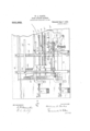
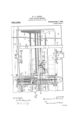
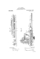
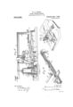
In the drawings, Figures 1 and 2 taken together constitute a 4 taken together constitute a front elevation; Fig. 5 is a section on the line wm of Fig. 2; Fig. 6 is a detail perspective of the mechanism for bringing the first stamp of a row'to position of registry; Fig. 7 is a detail perspective of my means for raising the carria e clear of the sheet of stamps.
The bed obstructed surface slightly wider than a sheet of stamps and slightly more than twice the length of transverse waysat the ends of the bed 1 is a bridge 2, made up of end pieces and four longitudinal bars 2, 2', and 2". A carriage 3 is mounted to travel longitudinally upon the bridge 2. Y It will thus be seen that the carriage moves, with reference to the bed 1, in all four directions-longitudinally upon the bridge 2, and transversely with the bridge 2.
Secured tothe carriage 3 is a serrated blade 4 (see Fig. 3) the'serrations of which bear against the face of the sheet of stamps to carry it along on the bed 1 I also secure spring fingers 5 to the carriage to further grip and carry the sheet of stamps. It
that movement of the carriage 3 to the left will carry the sheet of stamps longitudinally; that when the carriage is raised and moved with the bridge transverselyand again lowered to engagement, it will carry the sheet of stamps back with it; hat when it is again moved down transversely it will bring another rowof stamps into line for aflixing, and that when it is moved up to the starting point, the first stamp of the next row will be brought to place for affixing.
I will now describe the several above enumerated.
1. Moving t/ze'sta-mp to posz'tz'on.*This is really the last half of a preceding movement, but is best described at this point. 6 is the hand lever which is pivoted to a bracket a transverse fixed plate 7. The hand lever 6 has a key 8 (or, if preferred, a handle) by which it may be forced downwardly by the hand. Mounted upon the carriage 3 is a rack 9 and rigidly mounted upon the plate 7 is a bent arm 10 (see Fig. 4). Pivoted to the end of arm 10 is a dog 11, which engag s the rack 9 operations Patented Sept. 7,1909;
plan view; Figs. 3 and of the machine 1, has a flat, un-
a sheet of stamps. Mounted in 2 and the other to the forward end of the carriage 3, normally tending to draw the carriage to the right. If now we assume that the hand lever 6 has been depressed, the dog 13 will have engaged the next notch to the right on the rack 9; and when the lever 6 is raised (by the springs of the plunger as hereafter described) the bell-crank lever 12 will be swung upwardly forcing the dog 13 to the left until. the dog 11 drops by gravity into the next notch beyond its present position. This will have moved the rack 9 one'notch, with it the carriage 8, and,
through the grippers 4 and 5, the sheet of stamps will have been moved the width of one stamp. a
2. M oz'stemlng the stamp.-'Directly beneath the row of stamps and adjacent to the plunger, is. a moistening roller 15 (see Fig. 4) which is spring-held up against the gummed surface of the stamp next to be used, through an opening in the bed-plate, and which is moistened in any desired manner, as, for example, by a sponge 16. By this means the stamp is moistened just before it is usedthat is, during the last half of a preceding movement of the hand lever.
3. Swearing the stamp from the sheet a-o'wl afit'zving the same.An opening the size of a stamp is cut through the bed 1 at 17. (See Figs. 4 and 5.) The periphery of this opening is preferably provided with a hardened steel cutting edge 18 set in upon the surface. Mounted through the plate 7 are guide rods 19, which are free to reciprocate in said plate 7. Secured to the lower ends of these rods a rectangular-shaped presser 20, the interior opening of which is the same size and registers with the opening 17. Secured to the upper ends of the rods 17 is a rectangularshaped yoke 21, and interposed between the yoke 21 and the upper surface of the plate 7 and over the guide rods 19 are springs 22, which tend to raise the yoke 21 and the prcsser 20. In the yoke 21 and, in an opening in the plate 7 is a guide casing 22, rectangular in cross section and having an interior cross sectionequal to that of the opening 17. Within this casing 22 is the stamp plunger F23. which has the same cross section as the opening 1.7, and is, of
course, the proper size to wit out a stamp.
The stamp plunger 23 1s link-pivoted to the hand lever 15. Secured to the hand lever 6 is a yoke :24, and to the yoke 24 are secured rods 25 which, at their hiwer ends pass through the yoke 21 and are free to reciprocate therein. Over these rods are placed springs 26 which tend to force the yokes apart. The springs 26 are considerably stronger than the springs 22, for reasons which will appear presently. The operation is as follows: Assuming a stamp to be in placeover the opening 17, when pressure is applied to the hand lever 6-the springs 26 being unitedly stronger than the springs 22 nnitedlythe presser 20 will be forced down upon the sheet of stamps and will hold the sheet firmly. The plunger 23 will then be forced down, and entering the opening 17 will sever and carry down the stamp to beafiixed upon an envelop previously placed beneath the opening 17 As soon as pres sure is removed from the hand lever 6 the parts will return to normal. position. It will also be noted that, in this movement, the dogs 11 and 13 have coiipcrated with the rack 9, as described in the second preceding operation, and moved the carriage one step,
bringing another stamp to place just as the plunger 23 clears the opening 17, and at the same time moistening'the stamp on the roller 15 as it moves to place.
1. Disengagz'ng the carriers from the sheet of stamps.When the last stampof a row has been afiixed it is necessary to lift the grippers at and 5 and move them over to en "gage the next row of stamps. The carriage 3 is provided with a longitudinal bar 63 which is suitably mounted on the transverse bars 6% and 65 and is preferably raised somewhat above the level of the carriage. The bar 63 is adapted to register with and travel through grooves 66 and 67 in the lower part of the transverse fixed plate 7, and these,
grooves are spaced-apart the width of a single row of stamps. The bar 63 is provided with indentations 68 and 69 which are spaced apart a distance equal to the distance between the cross pieces51 and 54.. Upon the carriage 3 are the flat bars 27, arranged at the four corners of the carriage. Pivoted to the bed 1 are lever arms 28, underneath which are compression springs 29 (see F '7) and over the free ends of which are slotthe carriage cannot rise, as it is held down by the lugs mmediately. after the hand lever 6 has completed the return stroke ailixing the last stamp in a row, the bars 27 pass out from under the lugs 31 and innnediately the springs 25) force the lovers 28 upwardly rated blade A lug 36 on sin le g ,side bar 72- ieeaaee as high as the yokes the carriage 3 by the to Fig. 5 it will be seen that the carriage 3 takes over the sides of the bars 2' and 2", so that when the carriage is raised as above described, it is not freed from the bridge 2. When the carriage is thus raised,'the ser- 4 and the spring fingers 5 will. be raised clear of the sheet of stamps.
5. Mowing t/ze! (rm/Maya to engage another row of stampa-Pivoted to the side ofthe base 1 is a lever arm 32, (see Fig. 1) which has a segmental rack ,33, which is engaged by a dog 34 pivoted to said? base. vA compression spring 35 is interposed between a lug on the base 1 :and said lever arm 32 and tends to force said arm toward the carriage. the carriage 3 travels in the plane of the arm 32. The lug 36 is so positioned on the carriage that it will strike and force down the lever arm 32 during, say, the aflixing of the last three stamps in a row. When the last stamp of a row is aflixed and just as the arms 27 pass out from under the lugs 31 and the carriage is raised, the lug 36 strikes the arm of the dog 34 and throws it out of engagement with the segment 33 Simultaneously the right hand end of the bar 63 passes beyond the transverse plate 7 and thus is disengaged from the cove 66 and the indentations '68 and 69 register with the cross pieceshl and 54. Thus the carriage is unlocked and the arm 32, driven by the spring 35,.strikes the lug 36 and forces the carriage the width of a row of stamps. The bridge 2 is provided with stops and 71 and when it is movedtransversely back- Wardly the stops 70 strike against the raised of the bed plate 1; when it is moved transversely forwardly the strike against the raised side, bar 73 of the bed plate 1. Thus the transverse movements of the bridge 2 are limited to the Width of a row of stamps. When the carriage and bridge are thus movedover, the ends of the plates 27 drop 0E from the-lever arms 28 and allow the serrated blade 4 and the spring fingers 5 to engage the sheet of stamps. .f Referring to Figs. 2 and 5 it will be seen that the lever arm 28 shown at the top of Fig. 2'drops into the notch 41 in the plate 27 when the carriage 3 is pushed to the rear by the spring 35 and remains in this notch duringpart of the movement of the carria e from the left to the right.
6. 'arrying the sheet of stamps back to the beginning end.The spring v14 having been put under tension by the movement of the carriage, as soon as the carriage is moved transversely, as above described, the rack 9 is moved laterally out of engagement with the do s 11 and 13, and the bar 63 registers witht e, groove 67 and, the carriage having been lowered, the cross pieces 51 and '54 are freed from the indentations 68 and 69. The
stops 71.
sheet of stamps 1s carried tension of the spring'14 then moves the carriage on the bridge back to the starting point.
7. Brinyin i716 sheet of stamps forward.Mounted to reciprocate upon the fixed plate 7 (see Figs. 2 and is a rack 42. A guide rod 43 connects the rack 42 with the bracket 6, and interposed between the bracket 6 and the rack 42 and placed over the guided-0d 43 is a compression spring 44. A dog 45 capable of engaging the rack 42 is pivoted to a bell-crank lever 46 which is piv oted to a bracket on the fixed plate 7, and this bell-cjrank lever 46 is, in turn, connected to the hand lever 6 by pivot-links. Upon the under side of the plate 7' is a lug 47' (see Fig. 5) which is connected to and moves with the rack 42. This lug 47 is so positioned as to engage a bar of the "carriage 3 as presently described.
Mounted integral with the rack 42 is a rack 48. (SeeFIg 2.) A dog 49, secured to the plate 7 engages the rack 48. The operation is as follows; \Vith each movementof the hand lever 6, the dog 45 moves the rack 42 one notch, the dog 49 engaging the rack 48 to prevent the rack 42 from moving back. Thus, step by step, the spring 44 is set up and the) lug 47 moved Aflat bar 50 has one end secured to a cross-piece 51 secured to the base of the machine (see Figs. 1 and. 2) and has the other, free and lying underneath the dog49. Upon the under side of this bar 50 is a downwardly projecting lug 52 (shown in dotted outline in Fig. On the carriage (see Fig. 1) is a lug 53. The operation is as follows: The spring 44 having been set up and the lug 47 having been moved back by the action of the dog 45 in the rack 42, when the carriage is moved over transversely as above described in the 5th movement, the lug will be under the bar 50; and as the carriage reaches its initial position at the right hand end, the lug 53 will strike the lug '52 on the underside of the bar 50, and as the lug 52 is beveled upwardly to slide over the lug 53, it will cause the bar 50 to be raised and to lift the dog 49 out of engagement with the rack 48. This will release the spring 44, and cause'it to move the lug 47 against a bar of the carriage 3 and move it transversely to the proper position when the bar 63 will again be brought into position for registry with the groove 66. Since the by the carriage, the sheet will thus be moved down to bring the next row in line for atlixing.
8. Bring i119 t/m'first stamp of (L row to positiom-It is now necessary to move the sheet of stamps up to position of registry under the affixing plunger. This is done in the following manner: Upon the cross-piece 51 and a cross-piece 54 (seeFigs. 1, 3 and 6) is a sliding plate 55, normally drawn to the left by 'a spring 56. Pivoted to this sliding plate 55 is a dog 57, which engages arack 58 secured to the cross pieces 51 and 54.
The do 57 is of s r111 material and ields 1 upwardly to pass over the teeth of the rack 58. It is also capable of moving horizontally in one direction on its pivot, but is held normally over the rack by a spring 59. The dog has at its fore end a downwardly and backwardly bent extension 57 as clearly shown in Fig. 6. Upon the carriage (see Figs. 1 and is a lug 60 with a hooked end, which is capable of engaging the extension 57 on the dog 5?, as hereafter de scribed. Slot-pivoted to the common plate of racks l2 and st? a bell-crank lever 61, which reciprocates on a pivot on the crosspiece 5 1-, and the other end of which engages a pin 62 on the sliding plate 55. It will now be seen that, as-the racks 42 and 48 are moved back, the bell-crank lever 61 will be moved, and that it, in turn, bearing against the pin 62, will move the sliding plate 55 and cause the dog 57 to engage in an advance-notch in the rack .58 With each step. Thus, as the hand lever is reciprocated in the process of affixing a row of stamps, the spring 56 is set up and the plate moves to the right. When the carriage has completed the movements-above described, and just as the carriage is moved forward transversely in the last (7th.) movement, the lug 60 engages the hooked or bent end 57 of the dog 57 and throws the dog sidewise, against the spring 59, out of the rack 58. This allows the spring 56 toact, through the engagement of the dog 57 with the lug 60 upon the carriage and to draw the same forward (to the left) until the limits of the slots in the plate 55 are reached, which is the predetermined position of registry for the sheet of stamps. Whenthe plate 55 has thus moved back, the dog 57 Will be snapped back by the spring59, owing to the depression or shoulder on the rack, preceding the first notch, and the lug 60 freed from the hooked end 57 of the dog 57. It will be noted that, as
theracks 42 and 48 have previously moved back, the bell-crank lever 61 is out of'the way of the pin 62 when it moves back. It
will thus be seenthat, after a sheet of stamps has been once put in place, by the. operation ofthe hand lever, every movement is caused;
. so that the operator has nothing to do but to feed in the envelops and apply power to the lever so lon as the sheet of stamps last-s. I am thus able totake a sheet of stamps, and
withoutsevering them in strips, or rolling or folding them, to sever and afiix them, one at a time by the simple operation of pressing down a single lever for each afiixing.
Having thus described my invention, and without limiting myself to the specific construction shown, What I claim is:
1. In a stamp affixing machine, means for severing and aflixing a stamp, means for bringing the next stamp to position for affixing, means for moving a sheet of stamps after one row has been aflixed, means for bringing another row of stamps into line for afiixing, and n'leans for bringing the first stamp of a row to registry for afli'xing by an auto inatic initial forward movement.
2. In a stamp afiixing machine, means for moistening, severing and aflixing a stamp, means for bringing the next stamp to position for aiiixing, means for moving a sheet of stamps after one row has been affixed, means for bringing another row of stamps into line for afiixing, and means for bringing the first stamp of a row to registry for aflixing by an automatic initial forward movement.
3. In a stamp affixing machine, means for moistening a stamp, means for severing and aflixing the stamp by the reciprocation of a lever, means for automatically bringing the next stamp to position for allixing by the action of said lever in afiixing the first stamp, and means for auton'iatically bringing the first stamp of the next row on a sheet to place for aflixmg by automatically moving the sheet of stamps back, then transversely, and then forward to bring the first stamp of the next row to position for afiixing: when one row has been dlfiXGd.
a. In a stamp aflixing machine, means for moistening, severing and aflixing a stamp, means for moving a sheet of stamps step by step .for successively aflixing all the stamps of one row, means for automatically moving the sheet back, transversely, and then for ward bringing the first stamp of the next row into position for afiixing and means for thus automatically bringing the several rows into position one row at a time for afiixing one stamp at a time until the entire sheet has been aflixed.
5. In a stamp aflixing machine, a bed for receiving a sheet of stamps flat, a moistening device, a reciprocating device for severing and affixing a stamp, means actuated by said reciprocating device for moving the sheet of stamps on said bed step by step for affixing, and means actuated by said reciprocating device for moving said sheet of stamps longitudinally and transversely to bring the next row of stamps in position for aliixing.
6. In a stamp afiixing machine, a bed for receiving a sheet of stamps fiat, a moistening device, a reciprocating device for severing and affixing a stamp, a carriage and means for gripping a sheet of stamps and automatic means actuatedby said reciprolating device for moving said carriage step by step, for releasing saidgripping means when a row of stamps has been afiixed, for moving said carriage transversely to engage the sheet of stamps to bring another row to place, for
moving said carriage and the sheet of stamps back, and also transversely tobring the next row into-position for aflixing.
7. In a stamp aflixin'g machine a bed. for receiving a sheet of stamps flat, a reciproeating device for severing and affixing a stamp, a carriage, means for locking said carriage'a aiiisttransverse movement while a rowof 5 amps is being afiixed, means for gripping the sheet of stamps, means actuated by said reciprocating device for moving said carriage step by step so as to bring success ve stamps of the row into position for aflixing, means for releasing said gripping means when a row of stamps has been affixed, means for releasing said carriage and allowing it to move transversely so ja's to engage the sheet of stamps and bring another row to place, meaiis for moving said carriage and the sheet of stamps back, and means for moving said carriagetransversely to bring the next row into position for affixing. i
8. In a stamp 'aflixing machine, a bed for receiving a sheet of stamps flat, a moistening device, a reciprocating devicefor severmeans for gripping a ing and aflixing a stamp, a carriage and sheet of stamps, and automatic means actuated by said reciprocating device for moving said carriage step by step, for releasing said gripping means when a row of stamps has been aflixed, for moving said carriage transversely to engage the sheet of stamps to bring another row to place, for moving said sheet of stamps back, and also transversely, and for moving said sheet of stamps forward to bring the first stamp of the next rowto. position for atiixing.
bringing the first stamp in the first row of a sheet of stamps to registry for affixing by an automatic initial forwar movement, means for bringing the next stamp to position for affixing, means for moving-a sheet of stamps after one row has been afiixed, means for bringing another row into line for atlixing, and means for severing and affixing the several stamps of the sheet comprising a base with an opening therein, a presser for engaging the surface of the sheet of stamps to hold it for severing, a plunger reciprocating within said presser and through said opening, springs for bringing said presser into action ahead of the plunger, and springs for returning said plunger.
10. In a machine for affixing stamps, a bed for receiving the sheet of stamps flat, a bridge capable of transverse movement over said bed, a carriage capable of longitudinal movement on said bridge, means for sevening and afiixing a stamp, means for grippin a sheet of 'stamps andmeans for moving sair carriage and said sheet of stamps step by 9; In a stamp aflixing machine, means for step; and automatic means for releasing the grip on said sheet, moving the bridge transversely and moving the sheet back to the beginning end, for moving the sheet transversely to bring another row of stamps in line for afiixing, and for bringing the first stamp to position for aifixing,
11. In a machine for affixing stamps, a reciprocatin hand lever, a plunger for severing and atfixing a stamp, a base for receiving a sheet of stamps, a carriage and gripper for moving the stamp sheet, ratchet mechanism actuated by said hand lever for moving the carriage step bystep, a bridge supporting said carriage, a spring for retracting said carriage, automatic means for raising said carriage and grippers from engagement with the sheet of stam s when the last stamp of a row has been a xed, automatic means for moving said .carriage and said bridge transversely the width of a 'row of stamps and lowering said carriage to grip the sheet, automatic means for permitting said spring to retract the carriage as soon as lowered to grip the sheet,-and automatic means set in" operation by the retraction of said carriage for bringing the first stamp of another row to place for afiixing. I V 1 12. In a stamp affixing machine, a base, a bridge having a transverse movement on said base, a carriage having a longitudinal movement on said bridge and capable of vertical movement on said bridge, levers and springs actingfon said levers, and lugs secured to said base and arms or bars on said carriage, whereby said, springs are compressed by engagement of said bars with said levers as the carriage moves forward and whereby said carriage is raised when said bars pass out from under said lugs.
13. Ina stamp affixing machine a lever pivoted to a fixed part of the machine, a spring normally holding said lever at an angle with the line of movement of the carriage, a carriage and means for moving the same step by step, a bridge supporting said carriage, a lug on said carriage capable of riding over the face of said lever, arack on said lever and a dog engag ng said rack and pivoted to a fixed part of the mach ne, whereby said lug sets up said spring by engaging said lever in its forward movement and whereby said lug throws said dog out of engagement at the proper time to permit said spring to move said bridge transversely.
14. In a stamp affixing machine the combination with a reciprocating hand lever, of I a means for severing and a'iiixing a stamp, means for moving a sheet of stamps step by step for afiixing, means for moving the sheet of stamps to the beginning end of the inacliine, means for moving the sheet toward the front into -line for-'atlixin; means connected with the hand lever for setting up a spring and ratchet mechanism and means for releasing said spring and ratchet mechanism at the proper time for bringing the stamp sheet into position for afiixing the first stamp of the first row of the sheet brought forward transversely.
15. In a stamp aflixing machine, in combination with a reciprocating hand lever, means for severing and affixing a stamp and means for moving a sheet of stamps step by step, a base, a bridge, a carriage and means for gripping a sheet of stamps, a ratchet mechanism actuated by said hand lever to move said carriage step by step, means actuated by the movement of said carriage to move the carriage transversely, at the proper time, means for retracting the said carriage, and means for moving said carriage transversely and forwardly to bring the first stamp of a next succeeding row into position for aiiixmg comprising a spring and ratchet mechanism for setting up said spring during the step by step movement by the reciprocation of said hand lever, a lug on said carriage for throwing said spring into action when the carriage has been retracted; and a second spring and ratchet mechanism and a hig on said carriage for throwing said last mentioned spring into action when said carriage has been moved forward transversely, and a lever mechanism eonneeting said first mentioned ratchet mechanism with said last mentioned ratchet mechanism whereby said last mentioned ratchet mechanism sets up its spring coincidently with the action of said' first mentioned ratchet nueclmnism.
in testimony whereof I have hereunto set my hand in the presence of two witnesses.
WILLlAM A. PARTIE. \YiiHLSSOSI E. A. KELLY, A. W. MAooMmin.
Priority Applications (1)
| Application Number | Priority Date | Filing Date | Title |
|---|---|---|---|
| US33399706A US933262A (en) | 1906-09-10 | 1906-09-10 | Stamp-affixing machine. |
Applications Claiming Priority (1)
| Application Number | Priority Date | Filing Date | Title |
|---|---|---|---|
| US33399706A US933262A (en) | 1906-09-10 | 1906-09-10 | Stamp-affixing machine. |
Publications (1)
| Publication Number | Publication Date |
|---|---|
| US933262A true US933262A (en) | 1909-09-07 |
Family
ID=3001685
Family Applications (1)
| Application Number | Title | Priority Date | Filing Date |
|---|---|---|---|
| US33399706A Expired - Lifetime US933262A (en) | 1906-09-10 | 1906-09-10 | Stamp-affixing machine. |
Country Status (1)
| Country | Link |
|---|---|
| US (1) | US933262A (en) |
-
1906
- 1906-09-10 US US33399706A patent/US933262A/en not_active Expired - Lifetime
Similar Documents
| Publication | Publication Date | Title |
|---|---|---|
| US1859633A (en) | Machine for making parquetry blocks | |
| US1978983A (en) | Stapling machine | |
| US1889250A (en) | Marking machine | |
| CN210558180U (en) | Paper separating mechanism | |
| US1971963A (en) | Pin ticketing machine | |
| CN106564036B (en) | Nailing machine | |
| US712547A (en) | Punch for mortising printers' plates. | |
| US719410A (en) | Wrapping-machine. | |
| US487679A (en) | Machine for making package-carriers | |
| US1801250A (en) | Work holder for slicing machines | |
| US2186569A (en) | Apparatus for attaching fasteners | |
| US2281896A (en) | Marking machine | |
| US841828A (en) | Stamp-affixing machine. | |
| US713247A (en) | Machine for reinforcing collars, &c. | |
| US1171729A (en) | Ticketing-machine. | |
| US1396406A (en) | Tagging-machine | |
| US1805219A (en) | Feeding mechanism for punch presses | |
| US683599A (en) | Machine for carding safety-pins. | |
| US9474A (en) | Spike-machine | |
| US2534893A (en) | Bag handle feeding machine | |
| US457782A (en) | A kimball | |
| US825908A (en) | Box-labeling machine. | |
| US405342A (en) | And clinchim machine | |
| US454554A (en) | Machine for cutting the edges of cards | |
| US973370A (en) | Stapling-machine. |