US9322388B2 - Natural-frequency adjusting mechanism for wave-power generator - Google Patents
Natural-frequency adjusting mechanism for wave-power generator Download PDFInfo
- Publication number
- US9322388B2 US9322388B2 US14/002,189 US201214002189A US9322388B2 US 9322388 B2 US9322388 B2 US 9322388B2 US 201214002189 A US201214002189 A US 201214002189A US 9322388 B2 US9322388 B2 US 9322388B2
- Authority
- US
- United States
- Prior art keywords
- wave
- mass
- additional
- power
- power generator
- Prior art date
- Legal status (The legal status is an assumption and is not a legal conclusion. Google has not performed a legal analysis and makes no representation as to the accuracy of the status listed.)
- Expired - Fee Related, expires
Links
- 230000007246 mechanism Effects 0.000 title claims description 67
- 238000007667 floating Methods 0.000 claims abstract description 182
- XLYOFNOQVPJJNP-UHFFFAOYSA-N water Substances O XLYOFNOQVPJJNP-UHFFFAOYSA-N 0.000 claims abstract description 98
- 230000033001 locomotion Effects 0.000 claims abstract description 77
- 230000004044 response Effects 0.000 claims abstract description 25
- 238000006243 chemical reaction Methods 0.000 claims description 22
- 230000005484 gravity Effects 0.000 claims description 14
- 238000010248 power generation Methods 0.000 description 19
- 238000013016 damping Methods 0.000 description 13
- 230000009467 reduction Effects 0.000 description 12
- 230000004048 modification Effects 0.000 description 10
- 238000012986 modification Methods 0.000 description 10
- 230000003534 oscillatory effect Effects 0.000 description 10
- 238000006073 displacement reaction Methods 0.000 description 9
- 230000010355 oscillation Effects 0.000 description 9
- 230000008859 change Effects 0.000 description 7
- 230000000694 effects Effects 0.000 description 7
- 239000013535 sea water Substances 0.000 description 7
- 238000010586 diagram Methods 0.000 description 3
- 230000010356 wave oscillation Effects 0.000 description 3
- 230000001133 acceleration Effects 0.000 description 2
- 239000011159 matrix material Substances 0.000 description 2
- 238000000034 method Methods 0.000 description 2
- 238000005086 pumping Methods 0.000 description 2
- 238000003756 stirring Methods 0.000 description 2
- 238000013519 translation Methods 0.000 description 2
- 230000009471 action Effects 0.000 description 1
- 230000008901 benefit Effects 0.000 description 1
- 230000008878 coupling Effects 0.000 description 1
- 238000010168 coupling process Methods 0.000 description 1
- 238000005859 coupling reaction Methods 0.000 description 1
- 238000013461 design Methods 0.000 description 1
- 239000000284 extract Substances 0.000 description 1
- 239000012530 fluid Substances 0.000 description 1
- 230000006872 improvement Effects 0.000 description 1
- 238000012423 maintenance Methods 0.000 description 1
- 239000007787 solid Substances 0.000 description 1
Images


Classifications
-
- F—MECHANICAL ENGINEERING; LIGHTING; HEATING; WEAPONS; BLASTING
- F03—MACHINES OR ENGINES FOR LIQUIDS; WIND, SPRING, OR WEIGHT MOTORS; PRODUCING MECHANICAL POWER OR A REACTIVE PROPULSIVE THRUST, NOT OTHERWISE PROVIDED FOR
- F03B—MACHINES OR ENGINES FOR LIQUIDS
- F03B13/00—Adaptations of machines or engines for special use; Combinations of machines or engines with driving or driven apparatus; Power stations or aggregates
- F03B13/12—Adaptations of machines or engines for special use; Combinations of machines or engines with driving or driven apparatus; Power stations or aggregates characterised by using wave or tide energy
- F03B13/14—Adaptations of machines or engines for special use; Combinations of machines or engines with driving or driven apparatus; Power stations or aggregates characterised by using wave or tide energy using wave energy
- F03B13/16—Adaptations of machines or engines for special use; Combinations of machines or engines with driving or driven apparatus; Power stations or aggregates characterised by using wave or tide energy using wave energy using the relative movement between a wave-operated member, i.e. a "wom" and another member, i.e. a reaction member or "rem"
- F03B13/20—Adaptations of machines or engines for special use; Combinations of machines or engines with driving or driven apparatus; Power stations or aggregates characterised by using wave or tide energy using wave energy using the relative movement between a wave-operated member, i.e. a "wom" and another member, i.e. a reaction member or "rem" wherein both members, i.e. wom and rem are movable relative to the sea bed or shore
-
- F—MECHANICAL ENGINEERING; LIGHTING; HEATING; WEAPONS; BLASTING
- F03—MACHINES OR ENGINES FOR LIQUIDS; WIND, SPRING, OR WEIGHT MOTORS; PRODUCING MECHANICAL POWER OR A REACTIVE PROPULSIVE THRUST, NOT OTHERWISE PROVIDED FOR
- F03B—MACHINES OR ENGINES FOR LIQUIDS
- F03B13/00—Adaptations of machines or engines for special use; Combinations of machines or engines with driving or driven apparatus; Power stations or aggregates
- F03B13/12—Adaptations of machines or engines for special use; Combinations of machines or engines with driving or driven apparatus; Power stations or aggregates characterised by using wave or tide energy
- F03B13/14—Adaptations of machines or engines for special use; Combinations of machines or engines with driving or driven apparatus; Power stations or aggregates characterised by using wave or tide energy using wave energy
- F03B13/16—Adaptations of machines or engines for special use; Combinations of machines or engines with driving or driven apparatus; Power stations or aggregates characterised by using wave or tide energy using wave energy using the relative movement between a wave-operated member, i.e. a "wom" and another member, i.e. a reaction member or "rem"
-
- F—MECHANICAL ENGINEERING; LIGHTING; HEATING; WEAPONS; BLASTING
- F03—MACHINES OR ENGINES FOR LIQUIDS; WIND, SPRING, OR WEIGHT MOTORS; PRODUCING MECHANICAL POWER OR A REACTIVE PROPULSIVE THRUST, NOT OTHERWISE PROVIDED FOR
- F03B—MACHINES OR ENGINES FOR LIQUIDS
- F03B15/00—Controlling
-
- F—MECHANICAL ENGINEERING; LIGHTING; HEATING; WEAPONS; BLASTING
- F05—INDEXING SCHEMES RELATING TO ENGINES OR PUMPS IN VARIOUS SUBCLASSES OF CLASSES F01-F04
- F05B—INDEXING SCHEME RELATING TO WIND, SPRING, WEIGHT, INERTIA OR LIKE MOTORS, TO MACHINES OR ENGINES FOR LIQUIDS COVERED BY SUBCLASSES F03B, F03D AND F03G
- F05B2250/00—Geometry
- F05B2250/40—Movement of component
- F05B2250/44—Movement of component one element moving inside another one, e.g. wave-operated member (wom) moving inside another member (rem)
-
- F—MECHANICAL ENGINEERING; LIGHTING; HEATING; WEAPONS; BLASTING
- F05—INDEXING SCHEMES RELATING TO ENGINES OR PUMPS IN VARIOUS SUBCLASSES OF CLASSES F01-F04
- F05B—INDEXING SCHEME RELATING TO WIND, SPRING, WEIGHT, INERTIA OR LIKE MOTORS, TO MACHINES OR ENGINES FOR LIQUIDS COVERED BY SUBCLASSES F03B, F03D AND F03G
- F05B2260/00—Function
- F05B2260/40—Transmission of power
- F05B2260/403—Transmission of power through the shape of the drive components
- F05B2260/4031—Transmission of power through the shape of the drive components as in toothed gearing
-
- F—MECHANICAL ENGINEERING; LIGHTING; HEATING; WEAPONS; BLASTING
- F05—INDEXING SCHEMES RELATING TO ENGINES OR PUMPS IN VARIOUS SUBCLASSES OF CLASSES F01-F04
- F05B—INDEXING SCHEME RELATING TO WIND, SPRING, WEIGHT, INERTIA OR LIKE MOTORS, TO MACHINES OR ENGINES FOR LIQUIDS COVERED BY SUBCLASSES F03B, F03D AND F03G
- F05B2270/00—Control
- F05B2270/10—Purpose of the control system
- F05B2270/18—Purpose of the control system to control buoyancy
-
- F—MECHANICAL ENGINEERING; LIGHTING; HEATING; WEAPONS; BLASTING
- F05—INDEXING SCHEMES RELATING TO ENGINES OR PUMPS IN VARIOUS SUBCLASSES OF CLASSES F01-F04
- F05B—INDEXING SCHEME RELATING TO WIND, SPRING, WEIGHT, INERTIA OR LIKE MOTORS, TO MACHINES OR ENGINES FOR LIQUIDS COVERED BY SUBCLASSES F03B, F03D AND F03G
- F05B2270/00—Control
- F05B2270/10—Purpose of the control system
- F05B2270/20—Purpose of the control system to optimise the performance of a machine
- F05B2270/202—Tuning to wave conditions
-
- Y—GENERAL TAGGING OF NEW TECHNOLOGICAL DEVELOPMENTS; GENERAL TAGGING OF CROSS-SECTIONAL TECHNOLOGIES SPANNING OVER SEVERAL SECTIONS OF THE IPC; TECHNICAL SUBJECTS COVERED BY FORMER USPC CROSS-REFERENCE ART COLLECTIONS [XRACs] AND DIGESTS
- Y02—TECHNOLOGIES OR APPLICATIONS FOR MITIGATION OR ADAPTATION AGAINST CLIMATE CHANGE
- Y02E—REDUCTION OF GREENHOUSE GAS [GHG] EMISSIONS, RELATED TO ENERGY GENERATION, TRANSMISSION OR DISTRIBUTION
- Y02E10/00—Energy generation through renewable energy sources
- Y02E10/30—Energy from the sea, e.g. using wave energy or salinity gradient
-
- Y02E10/38—
Definitions
- the present invention relates to a wave-power generator.
- the natural period of the floating body is designed to be smaller than the design wave period.
- the wave period in the actual marine area typically varies widely from 3 to 10 seconds, there is a problem in that the wave period in the actual marine area becomes significantly larger than the natural period of the floating body in some cases, so that the floating body does not effectively oscillate, thus reducing the capacity factor of the wave-power generator.
- the present invention has been made in view of such circumstances and provides a wave-power generator that is capable of adjusting the natural period (natural frequency) in response to changing wave period.
- the present invention provides a wave-power generator that is capable of using a short spring having a high spring constant, thus achieving a reduction in size.
- the wave-power generator of the present invention employs the following solutions.
- the present invention provides a wave-power generator that is provided with an oscillating body that is installed in a floating body via a spring and that linearly reciprocates in response to a fluctuation of a water surface and a generator that generates power by being driven based on the linear reciprocating motion of the oscillating body, the wave-power generator including an additional-mass body for adding an additional mass to a mass of the oscillating body.
- the oscillating body installed in the floating body via the spring linearly reciprocates in response to a fluctuation of the water surface.
- the generator is driven based on this linear reciprocating motion, thus generating power.
- the frequency fn can be calculated by using the following Equation (1) when it is assumed that the mass of the oscillating body is m, and the mass of the additional-mass body is ⁇ m.
- the spring constant k can be increased.
- the generator of the present invention can be any type of generator as long as it is driven based on the linear reciprocating motion of the oscillating body, and the driving force transferred to the generator may be directly obtained from the oscillating body (for example, a linear generator), may be indirectly obtained via another mechanism, or may be obtained via the additional-mass body.
- the additional mass of the additional-mass body may be adjustable.
- the frequency fn can be changed by changing the mass ⁇ m of the additional-mass body.
- the above-described wave-power generator according to the first aspect of the present invention may further include a conversion mechanism that converts the linear reciprocating motion of the oscillating body to rotational motion and a rotating body that is rotated by a torque extracted via the conversion mechanism and that drives the generator, in which the additional-mass body may be attached to the rotating body.
- the conversion mechanism converts the linear reciprocating motion of the oscillating body to rotational motion, the torque obtained after the conversion rotates the rotating body, and this rotation drives the generator. Then, the additional-mass body is attached to the rotating body, and the moment of inertia of the additional-mass body produced when it is rotated is utilized as an additional mass, thereby improving the effect of the additional mass.
- the additional-mass body is attached to the rotating body, and the moment of inertia of the additional-mass body produced when it is rotated is utilized as an additional mass, the weight of the additional mass does not directly act on the spring attached to the oscillating body.
- the free length and the deflection of the spring can be reduced, thus allowing a further reduction in size of the wave-power generator.
- the additional-mass body may be attached so as to be rotated together with the rotating body and may include a moving weight that can be moved in a radial direction from the center of rotation and a movement means for moving the moving weight in the radial direction.
- the additional-mass body is attached so as to be rotated together with the rotating body, and the moment of inertia of the additional-mass body produced when it is rotated is utilized as an additional mass.
- the additional-mass body of the first aspect of the present invention includes the moving weight that can be moved in a radial direction from the center of rotation, and the movement means moves the moving weight in the radial direction to locate it so as to obtain a desired additional mass.
- the moving weight is located at a radially outer side, the center of gravity moves to the radially outer side, thus increasing the moment of inertia to allow an increase in additional mass.
- the moving weight is located at a radially inner side, the center of gravity moves to the radially inner side, thus reducing the moment of inertia to allow a reduction in additional mass.
- the above-described wave-power generator according to the first aspect of the present invention may have a configuration in which a conversion mechanism that converts the linear reciprocating motion of the oscillating body to rotational motion and a rotating body that is rotated by a torque extracted via the conversion mechanism and that drives the generator are further included, and the additional-mass body is attached so as to be rotated together with the rotating body and is moved forward and backward with respect to water.
- the conversion mechanism converts the linear reciprocating motion of the oscillating body to rotational motion, the torque obtained after the conversion rotates the rotating body, and this rotation drives the generator. Then, the additional-mass body is attached so as to be rotated together with the rotating body and is moved forward and backward with respect to the water. Before the additional-mass body is submerged, the additional mass produced by the additional-mass body includes the moment of inertia of the additional-mass body and the resistance to stirring of an ambient fluid (typically, air). Then, when the additional-mass body is submerged in the water, the resistance is further increased by the viscosity and the specific gravity of water, thus increasing the additional mass. In this way, the additional mass can be adjusted by moving the additional-mass body forward and backward with respect to the water.
- an ambient fluid typically, air
- the additional-mass body may be provided with a blade whose base end portion is attached to the rotating body and that extends in a radial direction.
- the additional-mass body is provided with the blade whose base end portion is attached to the rotating body and that extends in the radial direction.
- the additional-mass body can be formed of only the blade or can be formed of a combination of the blade and, for example, a disc-shaped rotational plate-like body for obtaining the moment of inertia.
- a pitch angle of the blade may be changed.
- the angle of attack with respect to the water can be changed in the water by changing the pitch angle of the blade.
- the degree of adjustment of the additional mass can be further increased.
- the additional-mass body may be formed of a rotational plate-like body fixed to the rotating body; and the rotational plate-like body may be provided with a fin.
- the resistance in the water can be increased by attaching the fin to the plate-like body.
- the degree of adjustment of the additional mass can be increased.
- the fin may be moved forward and backward with respect to the rotational plate-like body.
- the resistance in the water can be adjusted by allowing the fin to be moved forward and backward with respect to the rotational plate-like body.
- the degree of adjustment of the additional mass can be further increased.
- any of the above-described wave-power generators according to the first aspect of the present invention it is preferable that a ball screw or a rack and a pinion be used as the conversion mechanism.
- a guide rail be provided in the floating body in the direction of the linear reciprocating motion
- a ball be provided between the guide rail and the oscillating body, and the guide rail, the oscillating body, and the ball constitute a linear motion guide.
- any of the above-described wave-power generators according to the first aspect of the present invention may further include an electric-power extracting mechanism that includes the oscillating body and the generator and that has an axis in the direction of the linear reciprocating motion of the oscillating body, in which the electric-power extracting mechanism may be placed such that the axis thereof matches a vertical axis that passes through the center of gravity of the floating body.
- the axis of the electric-power extracting mechanism is placed so as to match the vertical axis that passes through the center of gravity of the floating body, a heave motion of the floating body can be efficiently converted to electric power.
- any of the above-described wave-power generators according to the first aspect of the present invention may further include an electric-power extracting mechanism that includes the oscillating body and the generator and that has an axis in the direction of the linear reciprocating motion of the oscillating body, in which the electric-power extracting mechanism may be placed such that the axis thereof is located at a position displaced from a vertical axis that passes through the center of gravity of the floating body, parallel to the vertical axis.
- the axis of the electric-power extracting mechanism is placed at a position displaced from a vertical axis that passes through the center of gravity of the floating body, parallel to the vertical axis, a roll or pitch motion component of the floating body can be efficiently converted to electric power.
- any of the above-described wave-power generators according to the first aspect of the present invention may further include an electric-power extracting mechanism that includes the oscillating body and the generator and that has an axis in the direction of the linear reciprocating motion of the oscillating body, in which the electric-power extracting mechanism may be placed such that the axis thereof is kept in a horizontal direction.
- a horizontal motion component (yaw, surge, sway) of the floating body can be efficiently converted to electric power.
- any of the above-described wave-power generators according to the first aspect of the present invention may further include an electric-power extracting mechanism that includes the oscillating body and the generator and that has an axis in the direction of the linear reciprocating motion of the oscillating body, in which the electric-power extracting mechanism may be placed such that the axis thereof is inclined with respect to the vertical direction.
- a motion component in every direction (heave, sway, surge, roll, pitch, and yaw) of the floating body can be efficiently converted to electric power.
- the present invention provides a wave-power generator including: a floating body that floats on a water surface; an oscillating body that is installed in the floating body via a spring and that linearly reciprocates in response to a fluctuation of the water surface; and a generator that generates power by being driven based on the linear reciprocating motion of the oscillating body, in which at least one of a floating-body mass of the floating body, an added mass of water on the floating body, and a floating-body spring coefficient of the floating body is adjustable.
- the floating body oscillates in response to the fluctuation of the water surface, that is, the wave period; the oscillating body provided therein linearly reciprocates based on the oscillations of the floating body; and the generator is driven based on this linear reciprocating motion to generate power.
- the natural frequency fn′ of the floating body can be calculated by using the following Equation (2) when it is assumed that the mass of the floating body is m b , the added mass of water on the floating body is m ba , and the floating spring coefficient of the floating body is k b .
- the natural frequency fn′ of the floating body can be changed by changing at least one of the mass m b of the floating body, the added mass of water m ba on the floating body, and the floating spring coefficient k b of the floating body.
- the wave-power generator of the second aspect of the present invention because at least one of the mass m b of the floating body, the added mass of water m ba on the floating body, and the floating spring coefficient k b of the floating body is adjustable, the natural frequency of the floating body can be adjusted such that the floating body oscillates in response to the changing wave period in the actual marine area.
- the capacity factor of the wave-power generator can be improved.
- the generator of the present invention can be any type of generator as long as it is driven based on the linear reciprocating motion of the oscillating body to generate power, and the driving force transferred to the generator may be directly obtained from the oscillating body (for example, a linear generator), may be indirectly obtained via another mechanism, or may be obtained via the additional-mass body.
- the floating body may be provided with a projecting member projecting outward from a side thereof; and a floating-body cross-sectional area at the water surface may be adjustable by changing an orientation of the projecting member.
- the floating spring coefficient k b of the floating body can be expressed by the following Equation (3).
- k b ⁇ gA b (3)
- ⁇ is the density of water (for example, seawater)
- g is gravitational acceleration
- a b is the floating-body cross-sectional area at the water surface.
- the floating spring coefficient k b can be changed by changing the floating-body cross-sectional area A b .
- the projecting member that projects outward from the side of the floating body is provided, and the floating-body cross-sectional area is adjusted by changing the orientation of the projecting member.
- the floating spring coefficient k b of the floating body thus allowing adjustment of the natural frequency of the floating body.
- the projecting member is formed into a non-circular shape (for example, an elliptical shape or an oval shape) when viewed from the side of the floating body, and the projecting member can be rotated about an axis extending in the projecting direction to set a desired angular position or the projecting member can be moved forward and backward in the projecting direction.
- a non-circular shape for example, an elliptical shape or an oval shape
- a plurality of projecting members projecting outward from a side thereof may be provided in the vertical direction.
- the floating-body cross-sectional area can be easily adjusted. Furthermore, the projecting members that are submerged can also be used to adjust the added mass of water on the floating body.
- a water accommodating portion for accommodating water may be provided in the floating body; and a holding water level in the water accommodating portion may be adjustable.
- the water accommodating portion is provided in the floating body, and the holding water level in the water accommodating portion can be adjusted.
- the mass of the floating body thus allowing adjustment of the natural frequency of the floating body.
- the space in a bottom portion of the floating body may be used, or a water tank may be provided at a side portion of the floating body.
- a hydraulic pump may be used as a pump that pumps water into the water accommodating portion from outside of the floating body and/or that discharges the water in the water accommodating portion to the outside of the floating body.
- a hydraulic pump is used as the pump for pumping water between the outside of the floating body and the water accommodating portion. Since the hydraulic pump is driven by water hammering and requires no electric power, electric power generated by using wave power is not wasted, and thus the power generation efficiency of the wave-power generator is not reduced.
- any of the above-described wave-power generators according to the second aspect of the present invention may further include an additional-mass body for adding an additional mass to a mass of the oscillating body, in which the additional mass of the additional-mass body may be adjustable.
- the additional mass of the additional-mass body can be adjusted, thus making it possible to adjust the natural period of the oscillating body in response to the wave period. Therefore, the capacity factor of the wave-power generator can be improved.
- the wave-power generator of the present invention because at least one of the mass m b of the floating body, the added mass of water m ba on the floating body, and the floating spring coefficient k b of the floating body is adjustable, it is possible to adjust the natural frequency of the floating body such that the floating body oscillates in response to the changing wave period in the actual marine area.
- the capacity factor of the wave-power generator can be improved.
- an advantageous effect is afforded in that it is possible to use a short spring having a high spring constant, thus achieving a reduction in size of the device.
- FIG. 1 is a perspective view showing, in outline, the configuration of a wave-power generator according to a first embodiment of the present invention.
- FIG. 2 is a plan view showing an additional-mass body shown in FIG. 1 .
- FIG. 3 is a diagram showing an oscillatory model of the wave-power generator shown in FIG. 1 .
- FIG. 4 is a plan view showing a first modification of the additional-mass body.
- FIG. 5 is a side view showing a second modification of the additional-mass body.
- FIG. 6 is a perspective view showing, in outline, the configuration of a wave-power generator according to a second embodiment of the present invention.
- FIG. 7 is a perspective view showing forward-and-backward movement of blades of an additional-mass body shown in FIG. 6 .
- FIG. 8 is a perspective view showing a first modification of an additional-mass body shown in FIG. 7 .
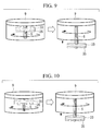
- FIG. 9 is a perspective view showing a second modification of the additional-mass body shown in FIG. 7 .
- FIG. 10 is a perspective view showing a third modification of the additional-mass body of the additional-mass body shown in FIG. 7 .
- FIG. 11 is a perspective view showing a wave-power generator according to a third embodiment of the present invention.
- FIG. 12 is a partial cutaway perspective view showing the inside of the wave-power generator shown in FIG. 11 .
- FIG. 13A is a side view showing an orientation change of a projecting member of the wave-power generator shown in FIG. 11 .
- FIG. 13B is a side view showing an orientation change of the projecting member of the wave-power generator shown in FIG. 11 .
- FIG. 14 is a diagram showing an oscillatory model of the wave-power generator shown in FIG. 11 .
- FIG. 15 is a perspective view showing a modification of the wave-power generator shown in FIG. 11 .
- FIG. 16 is a longitudinal sectional view showing a wave-power generator according to a fourth embodiment of the present invention.
- FIG. 17 is a longitudinal sectional view showing a modification of the wave-power generator shown in FIG. 16 .
- FIG. 18 is a view showing, in outline, the configuration of a wave-power generator according to a fifth embodiment of the present invention.
- FIG. 19 is a diagram showing a model of the entire oscillatory system including a floating body shown in FIG. 18 .
- FIG. 20 is a sectional view of a wave-power generator according to a sixth embodiment of the present invention, viewed from the side.
- FIG. 21 is a view showing, in outline, the configuration of the wave-power generator shown in FIG. 20 .
- FIG. 22 is a view showing a model of the entire oscillatory system including a floating body shown in FIG. 20 .
- FIG. 23 is a cutaway perspective view showing a configuration in which generators are provided at upper and lower portions of a ball screw shaft.
- FIG. 24 is a longitudinal sectional view showing, in outline, the configuration of a conversion mechanism of a wave-power generator according to a seventh embodiment of the present invention.
- FIG. 25 is a longitudinal sectional view showing an oscillating-body unit shown in FIG. 24 .
- FIG. 26 is a side sectional view showing the conversion mechanism shown in FIG. 24 .
- FIG. 27 is a longitudinal sectional view showing a modification of the seventh embodiment of the present invention.
- FIG. 28 is a longitudinal sectional view showing, in outline, the configuration of a conversion mechanism of a wave-power generator according to an eighth embodiment of the present invention.
- FIG. 29 is a longitudinal sectional view showing an electric-power extracting mechanism shown in FIG. 28 .
- FIG. 30 is a transverse sectional view showing the wave-power generator shown in FIG. 28 .
- FIG. 31 is a view showing a yawing motion.
- FIG. 32 is a longitudinal sectional view showing a first modification of the wave-power generator shown in FIG. 28 .
- FIG. 33 is a longitudinal sectional view showing a second modification of the wave-power generator shown in FIG. 28 .
- FIG. 1 shows, in outline, the configuration of a wave-power generator according to the first embodiment.
- a wave-power generator 1 is provided with a box-shaped floating body 2 that floats on a water surface 7 of the ocean with its upper portion exposed.
- the floating body 2 contains a weight (oscillating body) 3 that is installed in the floating body 2 via a spring 4 , a ball screw shaft (rotating body) 5 that is rotated with respect to the weight 3 , an additional-mass body 6 that is fixed to the ball screw shaft 5 , and a generator 8 that is driven by the ball screw shaft 5 , to generate power.
- the weight 3 linearly reciprocates in the vertical direction at a predetermined natural frequency by receiving vertical oscillations of the floating body 2 that are produced by the heave of the water surface 7 caused by wave power. During the linear reciprocating motion, the weight 3 moves vertically via a guide (not shown), without rotating. The weight 3 is supported by the spring 4 so as to allow relative movement with respect to the floating body 2 .
- the ball screw shaft 5 is rotated about the axis thereof by the linear reciprocating motion of the weight 3 .
- the additional-mass body 6 is fixed to a lower end of the ball screw shaft 5 so as to be rotated together with the ball screw shaft 5 .
- the generator 8 is provided at an upper end of the ball screw shaft 5 and is rotated in one direction or in the other direction by the rotation of the ball screw shaft 5 , thereby generating power.
- the additional-mass body 6 is provided in an air chamber located below a base plate 9 .
- the additional-mass body 6 includes a ring-shaped body 10 that has the same center of rotation as the ball screw shaft 5 , four moving-weight ball screw shafts 12 that extend in vertical and horizontal directions in plan view as shown in FIG. 2 , moving weights 14 that are provided on the moving-weight ball screw shafts 12 , and movement motors (movement part) 16 that rotationally drive the moving-weight ball screw shafts 12 about the axes thereof.
- each of the moving-weight ball screw shafts 12 is fixed to the ball screw shaft 5 , the moving ball screw shaft 12 radially extends and passes through the ring-shaped body 10 , and the other end thereof is connected to the corresponding movement motor 16 .
- the moving weights 14 are displaced radially in response to the rotations of the moving-weight ball screw shafts 12 .
- the movement motors 16 are driven based on an instruction sent from a control section (not shown) and are fixed to the ring-shaped body 10 .
- the additional-mass body 6 In the additional-mass body 6 , the ring-shaped body 10 , the moving-weight ball screw shafts 12 , the moving weights 14 , and the movement motors 16 are integrally rotated together with the ball screw shaft 5 , after the radial locations of the moving weights 14 are determined by the movement motors 16 . Therefore, an additional mass of the additional-mass body 6 produced by the moment of inertia when it is rotated can be changed in response to the radial locations of the moving weights 14 . Specifically, if the moving weights 14 are located at the radially outer sides (closer to the ring-shaped body 10 ), the centers of gravity move to the radially outer sides, thus increasing the moment of inertia to allow an increase in additional mass. In contrast, if the moving weights 14 are located at the radially inner sides (closer to the ball screw shaft 5 ), the centers of gravity move to the radially inner sides, thus reducing the moment of inertia to allow a
- the wave-power generator 1 having the above-described configuration, when wave oscillations are received by the floating body 2 , the weight 3 oscillates in the vertical direction at a predetermined natural frequency due to the additional mass of the additional-mass body 6 in which the radial locations of the moving weights 14 have been adjusted so as to correspond to the wave period. Then, based on a linear reciprocating motion caused by this oscillation, the generator 8 is driven to perform power generation, thus extracting electric power.
- FIG. 3 shows an oscillatory system model of the wave-power generator 1 shown in FIG. 1 .
- damping constant for example, the generator 8
- Equations of motion are expressed as follows.
- Equation (6) can be transformed into the following Equation (8).
- Equation (8) is substituted into Equation (5), the following equation is obtained.
- Equation (9) When Equation (9) is substituted into Equation (4), the following equation is obtained.
- Equation (10) When Equation (10) is rearranged, the following equation is obtained.
- Equation (11) is rearranged by using the left side and the middle part of Equation (9), the following equation is obtained.
- [Formula 10] ⁇ m ⁇ umlaut over (z) ⁇ b +( m m + ⁇ m ) ⁇ umlaut over (z) ⁇ m ⁇ ( c+ ⁇ c ) ⁇ b +( c+ ⁇ c ) ⁇ m ⁇ kz b +kz m 0 (12)
- Equation (11) and Equation (12) are expressed in matrix form, the following equation is obtained.
- Equation (1) and Equation (14) because the natural frequency of the weight 3 can be adjusted, the weight 3 can be made to resonate in response to the changing wave period, thus resulting in an improvement in the capacity factor of the wave-power generator 1 .
- the radial locations of the moving weights 14 are adjusted at the outer circumferential sides of the ring-shaped body 10 by using, as in FIG. 2 , the moving-weight ball screw shafts 12 and the movement motors 16 .
- the moment of inertia can be increased more than in the case shown in FIG. 2 .
- the radial locations of the moving weights 14 are adjusted by using a link mechanism.
- a fixed part 20 that rotates together with the ball screw shaft 5 and a slider 21 that reciprocates in the axial direction of the ball screw shaft 5 with respect to the fixed part 20 are provided.
- Pivotable first arms 22 are symmetrically attached to the fixed part 20
- one end of each second arm 23 is pivotally attached to the other end of each of the first arms 22 .
- the two second arms 23 are pin-supported at the slider 21 while crossing over each other, and the moving weights 14 are attached to the distal ends thereof.
- the slider 21 is moved forward and backward with respect to the fixed part 20 by an actuator (not shown), thereby making it possible to adjust the radial locations of the moving weights 14 .
- This embodiment is the same as the first embodiment in the configuration in which the weight 3 linearly reciprocates, and the generator 8 generates power; therefore, identical reference symbols are assigned, and a description thereof will be omitted. Since a wave-power generator 30 of this embodiment differs from that of the first embodiment in the configuration of the additional-mass body, a description thereof will be given.
- An additional-mass body 32 is formed of blades 34 and a circular-plate-like inertia disc 33 that is rotated together with the ball screw shaft 5 .
- the inertia disc 33 is fixed to the ball screw shaft 5 so as to be rotated together with the ball screw shaft 5 . Therefore, the additional mass obtained by the inertia disc 33 is the moment of inertia of a circular plate and has a fixed value.
- Base ends of the blades 34 are fixed to a lower end portion of the ball screw shaft 5 , and the blades 34 extend in radial directions. Although the number of blades 34 is two in FIG. 6 , it may be three or more.
- a lower end 2 a of a cylindrical casing of the floating body 2 is an open end. Therefore, the space where the additional-mass body 32 is installed, specifically, the space below the base plate 9 in the floating body 2 , serves as an air chamber, and the water surface is located at the position of the lower end 2 a of the cylindrical casing of the floating body 2 .
- the blades 34 are moved forward and backward with respect to the water below the lower end 2 a of the floating body 2 .
- the additional mass obtained by the additional-mass body 32 includes the moment of inertia of the inertia disc 33 and the blades 34 and the resistance of the blades 34 to stirring of air.
- the resistance added to the blades 34 is further increased due to the viscosity and the specific gravity of water, thus increasing the additional mass.
- the additional mass can be adjusted by moving the blades 34 of the additional-mass body 32 forward and backward with respect to the water.
- the pitch angles of the blades 34 submerged in the water may be changed. Specifically, as shown in the right view of FIG. 8 , when the pitch angles are changed so as to obtain larger angles of attack than those shown in the left view of FIG. 8 , the water resistance is increased, thus further increasing the additional mass. In this way, when the angles of attack of the blades 34 with respect to the water are changed in the water, the degree of adjustment of the additional mass can be further increased.
- fins 35 serving as additional resistance objects may be added to the inertia disc 33 .
- the fins 35 are attached so as to protrude downward from the lower surface of the inertia disc 33 .
- the fins 35 are attached so as to form substantially an X-shape when the inertia disc 33 is viewed from below. Note that the shape of the attached fins 35 is not limited to the X-shape.
- the fins 35 provided on the lower surface of the inertia disc 33 increase the resistance in the water, thus adjusting the additional mass. Furthermore, because the fins 35 are formed integrally with the inertia disc 33 , the device configuration is simplified.
- the fins 35 attached to the lower surface of the inertia disc 33 are each radially divided into multiple pieces which can be moved forward and backward at individual radial locations.
- the fins 35 located at the radially outer sides are moved forward in order to obtain a larger additional mass
- the fins 35 located at the radially inner sides are moved forward in order to obtain a smaller additional mass.
- the degree of adjustment of the additional mass can be finely set.
- FIGS. 11 and 12 show, in outline, the configuration of a wave-power generator of the third embodiment; wherein FIG. 11 is an external perspective view, and FIG. 12 is a cutaway perspective view.
- This embodiment is the same as the first embodiment in the configuration in which the weight linearly reciprocates, and the generator generates power; therefore, a description thereof will be omitted.
- a weight 103 is supported by a spring 104 whose lower end is fixed to a base plate 109 , so as to allow relative movement with respect to a floating body 102 .
- Projecting members 110 that project outward from the side surface of the floating body 102 are provided at upper portions of the floating body 102 .
- the vertical positions of the projecting members 110 are determined such that the water surface 7 is located somewhere in the vertical ranges of the projecting members 110 .
- the projecting members 110 are provided on the outer circumference of the floating body 102 at a pitch of about 90°. However, the number of projecting members 110 and the interval (pitch) therebetween may be set as desired, and they are determined in response to the required floating-body cross-sectional area.
- the projecting members 110 each have an elliptical shape or an oval shape when viewed from the side of the floating body 102 .
- any shape, except a true circle, can be adopted.
- the projecting members 110 are rotated about rotation axes L1 that extend in horizontal directions, by rotary motors 112 installed in the floating body 102 .
- rotary motors 112 By driving the rotary motors 112 , it is possible to make the long axis directions of the projecting members 110 match the vertical direction, as shown in FIG. 13A , or to make the long axis directions of the projecting members 110 match the horizontal direction, as shown in FIG. 13B . In this way, the floating spring coefficient of the floating body 102 is adjusted.
- the floating spring coefficient k b of the floating body 102 can be expressed by the following equation (3).
- k b ⁇ gA b (3)
- ⁇ is the density of water (for example, seawater)
- g is gravitational acceleration
- a b is the floating-body cross-sectional area at the water surface.
- the floating spring coefficient k b can be changed by changing the floating-body cross-sectional area A b .
- the angles of rotation of the projecting members 110 are determined by a control section (not shown). Specifically, the control section calculates the angles of rotation of the projecting members 110 based on a previously-obtained map or function from the wave period in an actual marine area measured by a wave-period measuring means, such as a wave height meter, and controls the rotary motors 112 to set the projecting members 110 at predetermined angles of rotation.
- a control section calculates the angles of rotation of the projecting members 110 based on a previously-obtained map or function from the wave period in an actual marine area measured by a wave-period measuring means, such as a wave height meter, and controls the rotary motors 112 to set the projecting members 110 at predetermined angles of rotation.
- a wave-power generator 101 having the above-described configuration, when wave oscillations are received by the floating body 102 , the floating body 102 whose natural period has been adjusted in response to the wave period by the angles of rotation of the projecting members 110 oscillates, and, furthermore, the weight 103 oscillates in the vertical direction at a predetermined natural frequency due to the additional mass of an additional-mass body 106 that has been adjusted in response to the wave period, together with the floating body 102 . Then, a generator 108 is driven based on the linear reciprocating motion caused by this oscillation, to generate power, thereby extracting electric power.
- FIG. 14 an oscillatory system model in this embodiment is shown in FIG. 14 .
- damping constant (for example, the generator 108 ) between the floating body 102 and the weight 103
- Equations of motion thereof are the same as Equation (13) and Equation (14) in the first embodiment.
- the plurality of projecting members 110 that project outward from the side of the floating body 102 are provided, and the floating-body cross-sectional area A b is adjusted by rotating the projecting members 110 .
- the floating spring coefficient k b of the floating body thus allowing adjustment of the natural frequency fn of the floating body. Therefore, because it is possible to adjust the natural frequency of the floating body such that the floating body oscillates in response to the changing wave period in the actual marine area and to effectively cause the weight 103 to linearly reciprocate, the capacity factor of the wave-power generator can be improved.
- the additional mass ( ⁇ m) is a mass added to the weight 103 , which serves as the oscillating body.
- the spring constant can be increased.
- a short stiff spring 104 can be used.
- the wave-power generator 101 can be reduced in size.
- the projecting members 110 may be provided at a plurality of stages (in the figure, two stages) in the vertical direction.
- the floating-body cross-sectional area A b can easily adjusted.
- the circumferential arrangement of the projecting members 110 that are located at one stage may be shifted from the circumferential arrangement of the projecting members 110 that are located at another stage.
- the projecting members 110 that are submerged may be utilized to adjust the added mass of water m ba (see Equation (2)) on the floating body 102 .
- the projecting members 110 of this embodiment are rotated about the horizontal axes L1 to change the floating-body cross-sectional area, instead of this, or, in addition to this, it is possible to adopt a configuration in which the projecting members 110 are moved forward and backward in the directions in which the projecting members 110 project (in radial directions of the floating body 102 ), to change the floating-body cross-sectional area.
- This embodiment has an identical configuration in which the weight 103 linearly reciprocates by receiving the oscillations of the floating body 102 , and the generator 108 extracts electric power; therefore, identical reference symbols are assigned to the same components, and a description thereof will be omitted.
- the present invention has a feature that the mass m b (see Equation (2)) of the floating body 102 is adjusted, thereby adjusting the natural frequency (or the natural period) of the floating body.
- a tubular body 114 is provided upright at the center position of the floating body 102 , and the tubular body 114 accommodates a mechanism for performing a linear reciprocating motion for power generation, constituted by the weight 103 , the spring 104 , a ball screw shaft 105 , the additional-mass body 106 , and the generator 108 .
- the tubular body 114 is provided in a watertight manner so as to prevent water from entering the inside thereof from outside.
- a water intake 116 and a water intake valve 117 are provided at a lower portion of the floating body 102 . Seawater is guided to the floating body 102 via the water intake 116 and the water intake valve 117 .
- a bottom portion of the floating body 102 serves as a water accommodating portion 115 for accommodating seawater, and the seawater taken into the water accommodating portion 115 is accumulated therein.
- a pump 119 for pumping the accumulated seawater is provided at the bottom portion of the floating body 102 .
- the seawater accumulated in the water accommodating portion 115 is pumped by the pump 119 and is discharged to the outside of the floating body 102 from a drain outlet 121 via a drain pipe 120 .
- a hydraulic pump is suitable for use as the pump 119 . Because a hydraulic pump is driven by water hammering action and requires no electric power, it has an advantage that electric power generated by using wave power is not wasted, and thus the power generation efficiency of the wave-power generator 101 is not reduced.
- the level of holding water accumulated in the water accommodating portion 115 can be adjusted. Because the mass m b of the floating body 102 is changed by this holding water level, the natural frequency fn′ of the floating body 102 can be adjusted (see Equation (2)).
- the control section (not shown) controls the water intake valve 117 and the pump 119 . Specifically, the control section calculates a desired holding water level based on a previously-obtained map or function from the wave period in the actual marine area obtained by the wave-period measuring means, such as a wave height meter, and controls the water intake valve 117 and the pump 119 to obtain the desired holding water level.
- the wave-period measuring means such as a wave height meter
- the mass m b of the floating body 102 is adjusted by changing the holding water level accumulated in the floating body 102 , the natural frequency (or the natural period) of the floating body 102 can be adjusted. Therefore, because it is possible to adjust the natural frequency of the floating body such that the floating body oscillates in response to the changing wave period in the actual marine area and to effectively cause the weight 103 to linearly reciprocate, the capacity factor of the wave-power generator can be improved.
- this embodiment can be modified as shown in FIG. 17 . Specifically, it is possible to adopt a configuration in which the tubular body 114 is inserted into the center of the floating body 102 in a watertight manner, an upper portion of the tubular body 114 is made to protrude upward from the floating body, and a lower portion of the tubular body 114 is made to protrude downward from the floating body 102 .
- this facilitates exchange or maintenance of the generator 108 , the additional-mass body 106 , etc.
- FIG. 18 shows, in outline, the configuration of a wave-power generator according to a fifth embodiment.
- a wave-power generator 201 includes a floating body 202 that floats on the water surface 7 with its upper portion exposed, an oscillating body 203 that is installed in the floating body 202 via a spring 204 , and an additional-mass body 206 that is directly attached to the oscillating body 203 .
- the wave-power generator includes a generator (not shown) that is driven, based on the linear reciprocating motion of the oscillating body 203 , to generate power.
- the oscillating body 203 has a mass m m , receives vertical oscillations of the floating body 202 , which are produced by the heave of the water surface 7 caused by wave power, and linearly reciprocates in the vertical direction at a predetermined natural frequency.
- the oscillating body 203 is supported by the spring 204 so as to allow relative movement with respect to the floating body 202 .
- a predetermined damping element 205 is provided between the floating body 202 and the oscillating body 203 .
- the damping element 205 is represented by an oscillatory model and includes, for example, the resistance of the generator.
- the additional-mass body 206 has a mass ⁇ m, is directly attached to the oscillating body 203 , and is detachable, for example. Furthermore, it is preferable that it can be exchanged with another additional-mass body 206 having a different mass, in response to the wave power status.
- the wave-power generator 201 when wave oscillations are received by the floating body 202 , the oscillating body 203 oscillates in the vertical direction at an appropriately-tuned natural frequency. Then, based on the linear reciprocating motion caused by this oscillation, the generator is driven to perform power generation, thus extracting electric power.
- FIG. 19 shows an oscillatory system model of the wave-power generator 201 shown in FIG. 18 .
- Equations of motion of the entire oscillatory system shown in FIG. 19 are expressed as the following equations.
- Equation (16) and Equation (17) are rearranged, the following equation is obtained.
- the additional mass ( ⁇ m) of the additional-mass body 206 is a mass added to the oscillating body 203 .
- the spring constant can be increased. Specifically, a short stiff spring can be used. Thus, it is possible to shorten the spring, allowing a reduction in size of the wave-power generator.
- the additional mass ⁇ m is utilized, like the fifth embodiment; however, an additional-mass body is attached to a rotating body that is rotated by an oscillating body, unlike the fifth embodiment in which the additional-mass body 206 is directly attached to the oscillating body 203 .
- a wave-power generator 210 of this embodiment includes a floating body 211 , a casing (floating body) 212 , and an electric-power extracting mechanism 213 .
- the floating body 211 is, for example, a hollow or solid member having a depth (length in the direction perpendicular to the plane of FIG. 20 ) of 5 m, a width (length in the horizontal direction in FIG. 20 ) of 5 m, and a height (length in the vertical direction in FIG. 20 ) of 20 m and having an almost rectangular shape.
- a through-hole 223 that communicates with an upper surface 221 and a lower surface 222 of the floating body 211 and that accommodates, in the inner portion (inside) thereof, an upper end portion (upper half) of the casing 212 is provided in a depthwise-and-widthwise center portion of the floating body 211 .
- the through-hole 223 is formed so as to correspond to the upper end portion of the casing 212 accommodated in the through-hole 223 .
- the casing 212 is a hollow circular-column-shaped (cylindrical) or hollow square-column-shaped member, the upper end portion thereof is accommodated in the through-hole 223 , and the electric-power extracting mechanism 213 is accommodated in the casing 212 . Furthermore, an opening formed at an upper end of the casing 212 is closed with a (first) lid member 231 , and an opening formed at a lower end of the casing 212 is closed with a (second) lid member 232 , thus forming an enclosed space S in the casing 212 .
- the electric-power extracting mechanism 213 includes a generator 241 , a ball screw shaft (rotating body: conversion mechanism) 242 , a weight (oscillating body) 243 , a spring 244 , and an inertia disc (additional-mass body) 245 .
- the generator 241 generates electric power (electric energy) when a rotating shaft 251 is rotated in one direction or in the other direction, and is installed in the casing 212 via a (first) supporting plate (frame) 252 .
- the supporting plate 252 is a plate-like member formed such that an outer circumferential surface thereof corresponds to an inner circumferential surface of the casing 212 , and a through-hole 253 that penetrates the supporting plate 252 in the plate-thickness direction and into which the rotating shaft 251 of the generator 241 is rotatably inserted is formed at the center portion of the supporting plate 252 . Furthermore, the supporting plate 252 is fixed to the inner circumferential surface of the casing 212 via a bracket 254 , and thus the generator 241 is installed in the enclosed space S at the upper end portion of the casing 212 .
- the ball screw shaft 242 is a bar-like member having an external thread portion 261 formed on the outer circumferential surface thereof and is installed in the casing 212 via a (second) supporting plate (frame) 262 and a (third) supporting plate (frame) 263 .
- the upper end of the ball screw shaft 242 is coupled to a lower end of the rotating shaft 251 of the generator 241 via a coupling 264 , the upper end portion of the ball screw shaft 242 is rotatably supported by the supporting plate 262 via a (first) bearing 265 , and the lower end portion of the ball screw shaft 242 is rotatably supported by the supporting plate 263 via a (second) bearing 266 .
- the inertia disc 245 is attached (fixed) to the lower end of the ball screw shaft 242 .
- the upper supporting plate 262 is a plate-like member formed such that an outer circumferential surface thereof corresponds to the inner circumferential surface of the casing 212 , and a through-hole 267 for accommodating the bearing 265 is provided at the center portion of the supporting plate 262 . Furthermore, the supporting plate 262 is fixed, via a bracket 268 , to the upper end portion of the casing 212 at a location lower than the supporting plate 252 .
- the lower supporting plate 263 is a plate-like member formed such that the outer circumferential surface thereof corresponds to the inner circumferential surface of the casing 212 , and a through-hole 269 for accommodating the bearing 266 is provided at the center portion of the supporting plate 263 . Furthermore, the supporting plate 263 is fixed to the lower end portion of the casing 212 via a bracket 270 .
- the weight 243 is an oscillating body that has a mass m and that vertically oscillates (linearly reciprocates) in the enclosed space S in the longitudinal direction (vertical direction) of the casing 212 , without rotating about the axis of the ball screw shaft 242 , along guide rails (conversion mechanisms) 281 provided on the inner circumferential surface of the casing 212 while extending in the longitudinal direction of the casing 212 .
- Balls (not shown) are provided between the weight 243 and the ball screw shaft 242 (specifically, at an inner periphery portion of the weight 243 ), and the weight 243 , the ball screw shaft 242 , and the balls constitute a ball screw (conversion mechanism).
- balls different from the balls constituting the ball screw are provided between the weight 243 and the guide rails 281 (specifically, at an outer periphery portion of the weight 243 ), and the weight 243 , the guide rails 281 , and the balls constitute a linear motion guide (conversion mechanism).
- the upper end of the spring 244 is attached (fixed) to a lower surface of the weight 243 , and the lower end thereof is attached (fixed) to an upper surface of the supporting plate 263 .
- the inertia disc 245 is a plate-like member that is attached to a lower end of the ball screw shaft 242 , that is rotated together with the ball screw shaft 242 , and that has a mass ⁇ m.
- the inertia disc 245 has a circular shape or a polygonal shape in top view (bottom view).
- the spring constant k of the spring 244 , the mass m of the weight 243 , and the mass ⁇ m of the inertia disc 245 are set (determined) such that the frequency fn falls within the range from 0.1 Hz to 0.5 Hz when they are substituted into Equation (1), previously shown.
- reference numeral 282 in FIG. 20 denotes a stopper that restricts upward movement of the weight 243 .
- FIG. 22 An oscillatory system model of this embodiment is shown in FIG. 22 .
- Equations of motion are the same as Equation (13) and Equation (14) in the first embodiment.
- the additional mass ( ⁇ m) is a mass added to the oscillating body.
- the spring constant can be increased.
- a short stiff spring 244 can be used.
- the wave-power generator 210 can be reduced in size.
- the wave-power generator 210 of this embodiment because the inertia disc 245 attached to the ball screw shaft 242 gives an inertial force to the ball screw shaft 242 , the moment of inertia of the ball screw shaft 242 can be increased, thus improving the effect of the additional mass.
- the wave-power generator 210 of this embodiment because the balls are provided between the weight 243 and the ball screw shaft 242 , thus reducing the resistance (mechanical loss) produced when the weight 243 linearly reciprocates, the power generation efficiency can be further improved.
- the inertia disc 245 is attached to the ball screw shaft 242 , and the moment of inertia of the inertia disc produced when it is rotated is utilized as an additional mass, the weight of the inertia disc 245 does not directly act on the spring 244 attached to the weight 243 .
- the free length and the deflection of the spring 244 can be reduced, thus allowing a further reduction in size of the wave-power generator 210 .
- the wave-power generator 210 of this embodiment because the balls are provided between the guide rails 281 and the weight 243 , thus reducing the resistance (mechanical loss) produced when the weight 243 linearly reciprocates, the power generation efficiency can be further improved.
- generator 241 is provided at only one end (upper end) of the ball screw shaft 242 in the sixth embodiment shown in FIG. 20
- generators 241 a and 241 b may be provided at both upper and lower ends of the ball screw shaft 242 , as shown in FIG. 23 .
- the generators 241 a and 241 b can be driven, without requiring a complicated mechanism.
- the ball screw shaft 242 is rotated clockwise when the weight 243 moves upward, and the ball screw shaft 242 is rotated counterclockwise when the weight 243 moves downward.
- the upper generator 241 a is rotationally driven only in a clockwise direction via a one-way clutch to perform power generation
- the lower generator 241 b is rotationally driven only in a counterclockwise direction via a one-way clutch to perform power generation.
- the upper generator 241 a generates power when the weight 243 moves upward
- the lower generator 241 b generates power when the weight 243 moves downward, thus making it possible to perform power generation at either of the generators 241 a and 241 b whenever the weight 243 , which linearly reciprocates, moves.
- a rack 272 that extends in the vertical direction is provided in the casing 212 .
- the rack 272 is fixed to the casing 212 .
- Guide rails 276 that vertically guide an oscillating-body unit 274 serving as the oscillating body are provided at both sides of the rack 272 .
- the guide rails 276 are fixed to the casing 212 .
- Balls (not shown) are provided between the guide rails 276 and the oscillating-body unit 274 , thus reducing the resistance (mechanical loss) produced when the oscillating-body unit 274 linearly reciprocates.
- the oscillating-body unit 274 is supported from below by the spring 244 .
- the upper end of the spring 244 is fixed to the lower surface of the oscillating-body unit 274
- the lower end of the spring 244 is fixed to the lower end of the casing 212 .
- the oscillating-body unit 274 includes, in a chassis 275 , the generator 241 , the weight 243 , and the inertia disc (additional-mass body) 245 , as in the sixth embodiment.
- the weight 243 is fixed to a bottom portion of the chassis 275 .
- the mass of the weight 243 is appropriately adjusted in response to the wave period in the actual marine area. Note that the position where the weight 243 is installed is not particularly limited as long as the weight 243 is attached to the chassis 275 . Furthermore, the weight 243 may be eliminated by adjusting the mass of the chassis 275 .
- the generator 241 and the inertia disc 245 are fixed to a rotating shaft (rotating body) 277 that extends in the horizontal direction.
- One end (left end in the figure) of the rotating shaft 277 is fixed to the chassis 275 via a radial bearing 279 .
- the generator 241 is fixed to the chassis 275 at the other end (right end in the figure) of the rotating shaft 277 .
- a pinion 278 is fixed to the rotating shaft 277 , and the rotating shaft 277 is rotated by the pinion 278 .
- the pinion 278 is engaged with the rack 272 and is rotated in response to the vertical displacement relative to the rack 272 .
- FIG. 27 this embodiment can be modified, as shown in FIG. 27 .
- two racks 272 a and 272 b are provided at left and right portions, and pinions 278 a and 278 b are engaged with the racks 272 a and 272 b , respectively.
- the pinions 278 a and 278 b are attached to the single rotating shaft 277 , and the rotating shaft 277 causes the generator 241 located at the center to generate power.
- the wave-power generator of the present invention is not limited to the configuration shown in the sixth embodiment or the seventh embodiment in which the linear reciprocating motion is converted to rotational motion by means of the ball screw or by means of the rack and the pinion, to perform power generation, and it can be applied to any configuration in which driving is caused based on the linear reciprocating motion of the oscillating body (weight), to perform power generation.
- the driving force transferred to the generator may be directly obtained from the oscillating body (for example, a linear generator), may be indirectly obtained via another mechanism, or may be obtained via the additional-mass body.
- FIGS. 28 to 31 Next, an eighth embodiment of the present invention will be described with reference to FIGS. 28 to 31 .
- each of the electric-power extracting mechanisms 213 has the same configuration as the electric-power extracting mechanism 213 of the sixth embodiment described using FIG. 20 .
- the casing 212 of the electric-power extracting mechanism 213 is a container accommodated in the floating body 211 ′, unlike the sixth embodiment in which it serves as the floating body itself.
- the electric-power extracting mechanism 213 includes, as main components, the generator 241 , the ball screw shaft 242 , the weight 243 , and the inertia disc 245 .
- the floating body 211 ′ is a container having a cylindrical shape in cross section.
- the electric-power extracting mechanisms 213 are installed at almost regular intervals around the outer circumference of the floating body 211 ′.
- the electric-power extracting mechanisms 213 are each installed in the vertical direction, and electric power is extracted through the linear reciprocating motion of the weight 243 in the vertical direction.
- the electric-power extracting mechanisms 213 are placed at positions offset from the vertical axis L1 that passes through the center of gravity of the floating body 211 ′. Therefore, the weights 243 in the electric-power extracting mechanisms 213 can be made to oscillate not only with heave (in the direction of the vertical axis L1) produced when the floating body 211 ′ oscillates but also with roll and pitch, which are motion components about axes perpendicular to the vertical axis L1. Thus, it is possible to efficiently convert wave energy into motion energy to perform power generation.
- an electric-power extracting mechanism 213 ′ can be placed with its axis kept in the horizontal direction, as shown in FIG. 32 .
- electric-power extracting mechanisms 213 ′′ with their axes inclined such that a motion component in every direction (heave, sway, surge, roll, pitch, and yaw) can be extracted.
- the configuration in which the electric-power extracting mechanism 213 ′ is placed in the horizontal direction to make the weight 243 linearly reciprocate in the horizontal direction or the configuration in which the electric-power extracting mechanisms 213 ′′ are inclined with respect to the vertical direction to make the weights 243 linearly reciprocate in inclined directions is also adopted; therefore, it is possible to convert wave energy into motion energy more efficiently to perform power generation.
Landscapes
- Engineering & Computer Science (AREA)
- Chemical & Material Sciences (AREA)
- Combustion & Propulsion (AREA)
- Mechanical Engineering (AREA)
- General Engineering & Computer Science (AREA)
- Other Liquid Machine Or Engine Such As Wave Power Use (AREA)
- Vibration Prevention Devices (AREA)
Abstract
Description
- {PTL 1} Japanese Translation of PCT International Application, Publication No. 2009-535560
- {PTL 2} Japanese Translation of PCT International Application, Publication No. 2009-518568
k b =ρgA b (3)
when the above settings are assumed, the following equation is obtained.
[Formula 7]
m m {umlaut over (z)} m =−c(ż m ż b)−Δm({umlaut over (z)} m −{umlaut over (z)} b)−Δc(ż m −ż b)=F b→m (9)
[Formula 10]
−Δm{umlaut over (z)} b+(m m +Δm){umlaut over (z)} m−(c+Δc)ż b+(c+Δc)ż m −kz b +kz m=0 (12)
when the above settings are assumed, the following equation is obtained.
[Formula 13]
M{dot over (x)}+C{dot over (x)}+Kx=F (14)
k b =ρgA b (3)
[Formula 16]
(m b +m ba){umlaut over (z)} b =−c b ż b −k b z b +F f +c(ż m −ż b)+k(z m −z b) (17)
[Formula 17]
(m b +m ba){umlaut over (z)} b+(c b +c)ż b −cż m+(k b +k)z b −kz m =F f(m m +Δm){umlaut over (z)} m −cż b+cż m −kz b +kz m=0 (18)
Here,
when the above settings are assumed, the following equation is obtained.
[Formula 20]
M{umlaut over (x)}+C{dot over (x)}+Kx=F (20)
Claims (18)
Applications Claiming Priority (9)
| Application Number | Priority Date | Filing Date | Title |
|---|---|---|---|
| JP2011-059142 | 2011-03-17 | ||
| JP2011059142 | 2011-03-17 | ||
| JP2011080748A JP5627528B2 (en) | 2011-03-17 | 2011-03-31 | Wave power generator |
| JP2011-080748 | 2011-03-31 | ||
| JP2011080747A JP5627527B2 (en) | 2011-03-17 | 2011-03-31 | Natural vibration adjustment mechanism of wave power generator |
| JP2011-080750 | 2011-03-31 | ||
| JP2011080750A JP5738043B2 (en) | 2011-03-31 | 2011-03-31 | Wave power generator |
| JP2011-080747 | 2011-03-31 | ||
| PCT/JP2012/056613 WO2012124747A1 (en) | 2011-03-17 | 2012-03-15 | Natural vibration adjustment mechanism of wave power generator |
Publications (2)
| Publication Number | Publication Date |
|---|---|
| US20140132003A1 US20140132003A1 (en) | 2014-05-15 |
| US9322388B2 true US9322388B2 (en) | 2016-04-26 |
Family
ID=49165892
Family Applications (1)
| Application Number | Title | Priority Date | Filing Date |
|---|---|---|---|
| US14/002,189 Expired - Fee Related US9322388B2 (en) | 2011-03-17 | 2012-03-15 | Natural-frequency adjusting mechanism for wave-power generator |
Country Status (5)
| Country | Link |
|---|---|
| US (1) | US9322388B2 (en) |
| EP (1) | EP2687716B1 (en) |
| CN (1) | CN103403342B (en) |
| AU (1) | AU2016200649B9 (en) |
| WO (1) | WO2012124747A1 (en) |
Cited By (2)
| Publication number | Priority date | Publication date | Assignee | Title |
|---|---|---|---|---|
| WO2020232454A1 (en) * | 2019-05-16 | 2020-11-19 | Vitalnrg, Inc. | Elongate wave energy generation devices and methods of using the same |
| US12122489B1 (en) * | 2023-10-31 | 2024-10-22 | South China University Of Technology | Ocean observation platform integrated with highly reliable wave energy generation mechanism and working method thereof |
Families Citing this family (34)
| Publication number | Priority date | Publication date | Assignee | Title |
|---|---|---|---|---|
| US9410527B2 (en) * | 2011-07-18 | 2016-08-09 | Sean N. Hsu | Tunable apparatus for generating energy from a fluid flow induced movement of a surface structure relative to a frame with at least one adjustable frame portion |
| US9581128B2 (en) * | 2012-05-25 | 2017-02-28 | University Of Massachusetts | Systems and methods for wave energy conversion |
| US8912678B2 (en) | 2012-08-03 | 2014-12-16 | Tsukasa NOZAWA | Wave activated power generation system with the rack and pinion mechanism |
| GB2506452B (en) * | 2012-09-30 | 2019-09-18 | Gregory Bruce | Dynamic tuning for wave energy conversion |
| TWM469378U (en) * | 2013-05-28 | 2014-01-01 | Smart Energy Inc | Power generating apparatus utilizing wave energy converted from gravity |
| GB2510928B (en) * | 2013-07-05 | 2015-09-09 | William Dick | A wave energy converter |
| FR3025004B1 (en) * | 2014-08-20 | 2016-09-02 | Charles Dumortier | INSTALLATION FOR THE PRODUCTION OF ELECTRIC ENERGY BY CONVERSION OF WAVE ENERGY |
| CN105604773B (en) * | 2014-09-24 | 2018-11-13 | 台州大浪泵业股份有限公司 | A kind of support cradle wave generator |
| CN105888949B (en) * | 2014-09-24 | 2018-09-18 | 嘉兴市迅程信息技术有限公司 | A kind of five wobble plate of green turtle shape, eight oscillator biserial spring formula ocean wave generator |
| US10024297B2 (en) * | 2014-12-18 | 2018-07-17 | Cyrus H Gerami | Reciprocating motion energy conversion apparatus |
| CN105114239B (en) * | 2015-08-18 | 2017-07-28 | 郭晨 | A kind of controllable posture wave-power device based on linear electric generator |
| CN106640513A (en) * | 2015-11-03 | 2017-05-10 | 林世轩 | Screw type kinetic energy generating device |
| WO2018006290A1 (en) * | 2016-07-06 | 2018-01-11 | 林世轩 | Screw type kinetic energy generation device |
| CN106870266B (en) * | 2017-04-13 | 2018-08-03 | 江苏科技大学 | It is a kind of to be used for underwater straight line differential power generator |
| US10253747B2 (en) * | 2017-09-05 | 2019-04-09 | Vladimir Shepsis | Energy generation from water waves and storage of energy |
| US10920739B2 (en) * | 2018-04-16 | 2021-02-16 | Moosa Nematollahi Saein | Wave-power system |
| CN108757293B (en) * | 2018-05-03 | 2020-06-05 | 繁昌县凯艺电子商务有限公司 | Combined type ocean energy collecting floater structure |
| CN109236545B (en) * | 2018-10-22 | 2020-05-05 | 杭州电子科技大学 | Wave energy power generation device and power generation method thereof |
| CN109209748B (en) * | 2018-11-30 | 2023-02-03 | 苏州大学 | A wave energy harvesting device |
| CN110725772A (en) * | 2019-10-09 | 2020-01-24 | 哈尔滨工程大学 | A direct-drive wave energy power generation device based on ball screw mechanism |
| CN111456885A (en) * | 2020-05-13 | 2020-07-28 | 杭州巨浪能源科技有限公司 | External gas-liquid tank and wave energy power generation device |
| CN111550355A (en) * | 2020-05-13 | 2020-08-18 | 杭州巨浪能源科技有限公司 | Floating type wave energy power generation equipment |
| CN111878293B (en) * | 2020-08-10 | 2021-08-24 | 金陵科技学院 | An oscillating wave energy power generation device with an anti-winding mechanism |
| CN111997823B (en) * | 2020-09-27 | 2022-09-06 | 香港理工大学 | Low-frequency and frequency-adjustable float type wave power generation device |
| CN112096558A (en) * | 2020-10-23 | 2020-12-18 | 鲁东大学 | Novel spiral wave power generation transmission device |
| CN113418584B (en) * | 2021-06-02 | 2022-05-10 | 上海交通大学 | A retractable sleeve calibration device for ship-mounted wave height gauge |
| CN113898521B (en) * | 2021-09-22 | 2024-03-08 | 鲁东大学 | Marine floating platform stand damping heave plate and wave energy collection device |
| CN114562406A (en) * | 2022-03-01 | 2022-05-31 | 浙江大学 | Multi-freedom-degree energy harvesting closed wave energy power generation device |
| CN114922786B (en) * | 2022-05-24 | 2025-07-25 | 上海电气风电集团股份有限公司 | Blade-free wind generating set based on vortex-induced vibration |
| WO2024081376A2 (en) * | 2022-10-12 | 2024-04-18 | Blue Lotus Energy Corporation | Wave driven electrical generator |
| CN116652362A (en) * | 2023-05-31 | 2023-08-29 | 哈尔滨理工大学 | A kind of inertial friction welding counterweight plate with adjustable moment of inertia |
| KR102804200B1 (en) * | 2023-11-02 | 2025-05-07 | 호서대학교 산학협력단 | A power generation device that utilizes variable inertia and performs resonant wave power generation |
| CN117550018B (en) * | 2024-01-12 | 2024-04-23 | 集美大学 | A wave energy power generation buoy and its variable area heave plate and control method |
| CN118640126B (en) * | 2024-05-31 | 2026-03-31 | 清华大学 | A fully enclosed oscillating floating body device and its control method, and a wave power generation system. |
Citations (15)
| Publication number | Priority date | Publication date | Assignee | Title |
|---|---|---|---|---|
| JPH05164036A (en) | 1991-12-13 | 1993-06-29 | Mitsubishi Heavy Ind Ltd | Barge type platform for wave activated power generation |
| CN1163988A (en) | 1997-01-21 | 1997-11-05 | 罗伊·麦克埃里斯特 | Wave power generation method and device |
| JP2002506162A (en) | 1998-03-07 | 2002-02-26 | ザ エンジニアリング ビジネス リミテッド | Extracting power from moving water |
| DE10055846A1 (en) | 2000-11-10 | 2002-05-29 | Erhard Otte | System for converting wave energy into electric power, comprises mass carried by floating object arranged capable of oscillating in or at guide unit which is displaced in vibratory movements |
| JP2005207332A (en) | 2004-01-23 | 2005-08-04 | Japan Science & Technology Agency | Gyroscope type wave activated power generation apparatus |
| WO2007045853A1 (en) | 2005-10-19 | 2007-04-26 | Marine Current Turbines Limited | Conversion of energy in waves and in tidal flow |
| JP2007132336A (en) | 2006-03-30 | 2007-05-31 | Sei Hybrid Kk | Wave activated power generation unit |
| WO2007064827A2 (en) | 2005-12-01 | 2007-06-07 | Ocean Power Technologies, Inc. | Wave energy converter utilizing internal reaction mass and spring |
| JP2007297929A (en) | 2006-04-28 | 2007-11-15 | Tokyo Institute Of Technology | Wave power generator |
| WO2007137426A1 (en) | 2006-05-30 | 2007-12-06 | Syncwave Energy Inc. | Wave energy converter |
| US7323790B2 (en) * | 2005-03-15 | 2008-01-29 | Ocean Power Technologies, Inc. | Wave energy converters (WECs) with linear electric generators (LEGs) |
| US20080309088A1 (en) * | 2005-04-19 | 2008-12-18 | Emmanuel Agamloh | Methods and Apparatus for Power Generation |
| US20090085357A1 (en) | 2005-12-01 | 2009-04-02 | Ocean Power Technologies, L | Wave energy converter with internal mass on spring oscillator |
| JP2009535566A (en) | 2006-05-01 | 2009-10-01 | オーシャン パワー テクノロジーズ,インク. | Damping (heave) plate with improved properties |
| CN201650572U (en) | 2010-03-04 | 2010-11-24 | 中山市探海仪器有限公司 | Power generation device for ocean wave power generation |
-
2012
- 2012-03-15 US US14/002,189 patent/US9322388B2/en not_active Expired - Fee Related
- 2012-03-15 WO PCT/JP2012/056613 patent/WO2012124747A1/en not_active Ceased
- 2012-03-15 CN CN201280011031.6A patent/CN103403342B/en not_active Expired - Fee Related
- 2012-03-15 EP EP12757378.0A patent/EP2687716B1/en not_active Not-in-force
-
2016
- 2016-02-02 AU AU2016200649A patent/AU2016200649B9/en not_active Ceased
Patent Citations (20)
| Publication number | Priority date | Publication date | Assignee | Title |
|---|---|---|---|---|
| JPH05164036A (en) | 1991-12-13 | 1993-06-29 | Mitsubishi Heavy Ind Ltd | Barge type platform for wave activated power generation |
| CN1163988A (en) | 1997-01-21 | 1997-11-05 | 罗伊·麦克埃里斯特 | Wave power generation method and device |
| JP2002506162A (en) | 1998-03-07 | 2002-02-26 | ザ エンジニアリング ビジネス リミテッド | Extracting power from moving water |
| US20040201223A1 (en) | 1998-03-07 | 2004-10-14 | Grinsted Timothy William | Extracting power from moving water |
| DE10055846A1 (en) | 2000-11-10 | 2002-05-29 | Erhard Otte | System for converting wave energy into electric power, comprises mass carried by floating object arranged capable of oscillating in or at guide unit which is displaced in vibratory movements |
| JP2005207332A (en) | 2004-01-23 | 2005-08-04 | Japan Science & Technology Agency | Gyroscope type wave activated power generation apparatus |
| US7323790B2 (en) * | 2005-03-15 | 2008-01-29 | Ocean Power Technologies, Inc. | Wave energy converters (WECs) with linear electric generators (LEGs) |
| US20080309088A1 (en) * | 2005-04-19 | 2008-12-18 | Emmanuel Agamloh | Methods and Apparatus for Power Generation |
| WO2007045853A1 (en) | 2005-10-19 | 2007-04-26 | Marine Current Turbines Limited | Conversion of energy in waves and in tidal flow |
| JP2009518568A (en) | 2005-12-01 | 2009-05-07 | オーシャン パワー テクノロジーズ,インク. | Wave energy converter using internal reaction mass and spring |
| US20070126239A1 (en) | 2005-12-01 | 2007-06-07 | Stewart David B | Wave energy converter utilizing internal reaction mass and spring |
| WO2007064827A2 (en) | 2005-12-01 | 2007-06-07 | Ocean Power Technologies, Inc. | Wave energy converter utilizing internal reaction mass and spring |
| US20090085357A1 (en) | 2005-12-01 | 2009-04-02 | Ocean Power Technologies, L | Wave energy converter with internal mass on spring oscillator |
| JP2007132336A (en) | 2006-03-30 | 2007-05-31 | Sei Hybrid Kk | Wave activated power generation unit |
| JP2007297929A (en) | 2006-04-28 | 2007-11-15 | Tokyo Institute Of Technology | Wave power generator |
| JP2009535566A (en) | 2006-05-01 | 2009-10-01 | オーシャン パワー テクノロジーズ,インク. | Damping (heave) plate with improved properties |
| WO2007137426A1 (en) | 2006-05-30 | 2007-12-06 | Syncwave Energy Inc. | Wave energy converter |
| US20090146429A1 (en) | 2006-05-30 | 2009-06-11 | Syncwave Energy Inc. | Wave energy converter |
| JP2009535560A (en) | 2006-05-30 | 2009-10-01 | シンクウェーブ エナジー インコーポレイテッド | Wave energy converter |
| CN201650572U (en) | 2010-03-04 | 2010-11-24 | 中山市探海仪器有限公司 | Power generation device for ocean wave power generation |
Non-Patent Citations (10)
| Title |
|---|
| Decision to Grant a Patent mailed Jan. 26, 2016, in CN Patent Application No. 201280011031.6. |
| Decision to Grant a Patent mailed Mar. 31, 2015, corresponding to Japanese patent application No. 2011-080750. |
| Decision to Grant a Patent mailed Sep. 2, 2014, corresponding to Japanese patent application No. 2011-080747. |
| Decision to Grant a Patent mailed Sep. 2, 2014, corresponding to Japanese patent application No. 2011-080748. |
| Extended European Search Report issued Nov. 18, 2014, corresponding to European patent application No. 12757378.0. |
| International Search Report corresponding to PCT/JP2012/056613, dated Jun. 12, 2012. |
| Notice of Acceptance in AU Application No. 2012229831, mailed Feb. 17, 2016. |
| Office Action issued May 6, 2015, corresponding to Chinese patent application No. 201280011031.6. |
| Office Action mailed Sep. 2, 2014, corresponding to Japanese patent application No. 2011-080750. |
| Written Opinion mailed Jun. 12, 2012, corresponding to PCT/JP2012/056613. |
Cited By (4)
| Publication number | Priority date | Publication date | Assignee | Title |
|---|---|---|---|---|
| WO2020232454A1 (en) * | 2019-05-16 | 2020-11-19 | Vitalnrg, Inc. | Elongate wave energy generation devices and methods of using the same |
| GB2599544A (en) * | 2019-05-16 | 2022-04-06 | Vitalnrg Inc | Elongate wave energy generation devices and methods of using the same |
| GB2599544B (en) * | 2019-05-16 | 2023-05-17 | Vitalnrg Inc | Elongate wave energy generation devices and methods of using the same |
| US12122489B1 (en) * | 2023-10-31 | 2024-10-22 | South China University Of Technology | Ocean observation platform integrated with highly reliable wave energy generation mechanism and working method thereof |
Also Published As
| Publication number | Publication date |
|---|---|
| AU2012229831A8 (en) | 2016-03-17 |
| EP2687716A4 (en) | 2014-12-17 |
| AU2012229831A1 (en) | 2013-09-19 |
| EP2687716B1 (en) | 2016-11-09 |
| WO2012124747A1 (en) | 2012-09-20 |
| CN103403342B (en) | 2016-03-30 |
| CN103403342A (en) | 2013-11-20 |
| AU2012229831B2 (en) | 2016-03-03 |
| US20140132003A1 (en) | 2014-05-15 |
| EP2687716A1 (en) | 2014-01-22 |
| AU2016200649A1 (en) | 2016-02-18 |
| AU2016200649B9 (en) | 2017-10-19 |
| AU2016200649B2 (en) | 2017-05-25 |
Similar Documents
| Publication | Publication Date | Title |
|---|---|---|
| US9322388B2 (en) | Natural-frequency adjusting mechanism for wave-power generator | |
| US8134281B2 (en) | Electrical generators for use in unmoored buoys and the like platforms with low-frequency and time-varying oscillatory motions | |
| US7443046B2 (en) | Wave energy converter utilizing internal reaction mass and spring | |
| US8067849B2 (en) | Wave energy converter with internal mass on spring oscillator | |
| JP6133844B2 (en) | Wave energy converter with rotary fluid spring | |
| WO2010056956A2 (en) | Wave energy converter | |
| US9518556B2 (en) | Apparatus and system for converting wave energy based on oscillating water column type | |
| JP5627527B2 (en) | Natural vibration adjustment mechanism of wave power generator | |
| JP2017505394A (en) | Vertical movement buoy point absorber | |
| JP5738043B2 (en) | Wave power generator | |
| GB2408075A (en) | Device for utilising wave energy | |
| EP3743619B1 (en) | Power take-off for a wave energy converter | |
| KR20110098492A (en) | Electronic Buoy Using Wave Force | |
| KR101631761B1 (en) | Offshore wind power equipment of floating type | |
| US20170175701A1 (en) | Wave energy generation device and methods of using the same | |
| JP5766484B2 (en) | Wave power generator | |
| CN119373643A (en) | A wave energy power generation device | |
| GB2409898A (en) | A rocking motion energy converter | |
| AU2012229831B8 (en) | Natural-frequency adjusting mechanism for wave-power generator | |
| KR101960705B1 (en) | A wave energy converter with variable stiffness | |
| JP2014214652A (en) | Wave power generation device | |
| KR102183633B1 (en) | Wave Power Generator Having Pendulum Movement Part | |
| US20040103658A1 (en) | Fluid wave electric generator system | |
| JP2003097408A (en) | Energy conversion device using swing | |
| TW201309901A (en) | An energy transforming system for ocean wave |
Legal Events
| Date | Code | Title | Description |
|---|---|---|---|
| AS | Assignment |
Owner name: THE UNIVERSITY OF TOKYO, JAPAN Free format text: ASSIGNMENT OF ASSIGNORS INTEREST;ASSIGNORS:HAYASHI, KENTARO;YASUNAGA, TAKESHI;IKESUE, SHUNICHI;AND OTHERS;SIGNING DATES FROM 20130820 TO 20130904;REEL/FRAME:031622/0151 Owner name: MITSUBISHI HEAVY INDUSTRIES, CO., LTD., JAPAN Free format text: ASSIGNMENT OF ASSIGNORS INTEREST;ASSIGNORS:HAYASHI, KENTARO;YASUNAGA, TAKESHI;IKESUE, SHUNICHI;AND OTHERS;SIGNING DATES FROM 20130820 TO 20130904;REEL/FRAME:031622/0151 |
|
| STCF | Information on status: patent grant |
Free format text: PATENTED CASE |
|
| FEPP | Fee payment procedure |
Free format text: MAINTENANCE FEE REMINDER MAILED (ORIGINAL EVENT CODE: REM.); ENTITY STATUS OF PATENT OWNER: LARGE ENTITY |
|
| LAPS | Lapse for failure to pay maintenance fees |
Free format text: PATENT EXPIRED FOR FAILURE TO PAY MAINTENANCE FEES (ORIGINAL EVENT CODE: EXP.); ENTITY STATUS OF PATENT OWNER: LARGE ENTITY |
|
| STCH | Information on status: patent discontinuation |
Free format text: PATENT EXPIRED DUE TO NONPAYMENT OF MAINTENANCE FEES UNDER 37 CFR 1.362 |
|
| FP | Lapsed due to failure to pay maintenance fee |
Effective date: 20200426 |