US9319829B1 - Wireless inductive pointer clock - Google Patents
Wireless inductive pointer clock Download PDFInfo
- Publication number
- US9319829B1 US9319829B1 US14/528,084 US201414528084A US9319829B1 US 9319829 B1 US9319829 B1 US 9319829B1 US 201414528084 A US201414528084 A US 201414528084A US 9319829 B1 US9319829 B1 US 9319829B1
- Authority
- US
- United States
- Prior art keywords
- wireless inductive
- pointer
- time code
- module
- control circuit
- Prior art date
- Legal status (The legal status is an assumption and is not a legal conclusion. Google has not performed a legal analysis and makes no representation as to the accuracy of the status listed.)
- Expired - Fee Related
Links
Images

Classifications
-
- G—PHYSICS
- G04—HOROLOGY
- G04R—RADIO-CONTROLLED TIME-PIECES
- G04R20/00—Setting the time according to the time information carried or implied by the radio signal
- G04R20/26—Setting the time according to the time information carried or implied by the radio signal the radio signal being a near-field communication signal
- G04R20/28—Tuning or receiving; Circuits therefor
-
- H04W4/008—
-
- G—PHYSICS
- G04—HOROLOGY
- G04C—ELECTROMECHANICAL CLOCKS OR WATCHES
- G04C11/00—Synchronisation of independently-driven clocks
- G04C11/04—Synchronisation of independently-driven clocks over a line
-
- G—PHYSICS
- G04—HOROLOGY
- G04C—ELECTROMECHANICAL CLOCKS OR WATCHES
- G04C13/00—Driving mechanisms for clocks by primary clocks
- G04C13/02—Circuit arrangements; Electric clock installations
- G04C13/021—Circuit arrangements; Electric clock installations primary-secondary systems using transmission of singular pulses for driving directly secondary clocks step by step
- G04C13/023—Circuit arrangements; Electric clock installations primary-secondary systems using transmission of singular pulses for driving directly secondary clocks step by step via existing transmission lines
-
- G—PHYSICS
- G04—HOROLOGY
- G04C—ELECTROMECHANICAL CLOCKS OR WATCHES
- G04C13/00—Driving mechanisms for clocks by primary clocks
- G04C13/02—Circuit arrangements; Electric clock installations
- G04C13/027—Circuit arrangements; Electric clock installations primary-secondary systems using transmission of other driving signals, e.g. coded signals
-
- G—PHYSICS
- G04—HOROLOGY
- G04R—RADIO-CONTROLLED TIME-PIECES
- G04R20/00—Setting the time according to the time information carried or implied by the radio signal
- G04R20/26—Setting the time according to the time information carried or implied by the radio signal the radio signal being a near-field communication signal
-
- H—ELECTRICITY
- H04—ELECTRIC COMMUNICATION TECHNIQUE
- H04W—WIRELESS COMMUNICATION NETWORKS
- H04W4/00—Services specially adapted for wireless communication networks; Facilities therefor
- H04W4/80—Services using short range communication, e.g. near-field communication [NFC], radio-frequency identification [RFID] or low energy communication
Definitions
- the present invention relates to clock technology and more particularly, to a wireless inductive pointer clock, which can be automatically synchronized to the time on a smart phone or tablet computer upon approaching of the smart phone or tablet computer.
- a conventional pointer clock generally comprises a dial, a movement, and three hands (the hour hand, the minute hand and the second hand).
- the second hand, the minute hand and the hour hand are pivotally coupled to the movement, and driven by the movement to indicate the time measured.
- a radio-controlled clock is synchronized by a time code transmitted by a radio transmitter connected to an atomic clock.
- the use of a radio-controlled clock may encounter problems. If a radio-controlled clock is used in a zone between two transmitters, it sometimes picks up one signal and sometimes another. Further, a radio-controlled clock may be unable to accurately receive the time code transmitted by a radio transmitter due to environmental interferences.
- the present invention has been accomplished under the circumstances in view. It is therefore the main object of the present invention to provide a wireless inductive pointer clock, which uses a wireless inductive receiver module to receive the time code of an electronic information device in a wireless manner, enabling the time on the wireless inductive pointer clock to be automatically synchronized to the time on the electronic information device.
- a wireless inductive pointer clock of the invention comprises a wireless inductive receiver module adapted for receiving a time code, a control circuit module electrically coupled to the wireless inductive receiver module and adapted for receiving the time code from the wireless inductive receiver module and converting the time code into a pointer drive signal, a movement electrically coupled to the control circuit module and adapted for receiving the pointer drive signal from the control circuit module and driving by the control circuit module, and a pointer unit comprising a plurality of pointers drivable by the movement.
- the wireless inductive receiver module of the wireless inductive pointer clock When approaching an electronic information device, such as smart phone or tablet computer to the wireless inductive pointer clock, the wireless inductive receiver module of the wireless inductive pointer clock receives the time code (hour, minute, second) of the electronic information device, enabling the control circuit module to drive the movement and the pointers of the pointer unit so that the time on the wireless inductive pointer clock is automatically synchronized to the time on the smart phone or tablet.
- the time code hour, minute, second
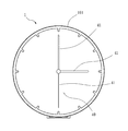
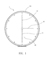
- FIG. 1 is a schematic front view of a wireless inductive pointer clock in accordance with the present invention.
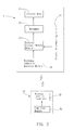
- FIG. 2 is a system block illustrating the wireless inductive pointer clock in operation with an electronic information device in accordance with the present invention.
- FIG. 3 is a circuit diagram of the wireless inductive pointer clock in accordance with the present invention.
- the wireless inductive pointer clock 1 comprises a wireless inductive receiver module 10 adapted for receiving a time code signal wirelessly, a control circuit module 20 electrically connected with the wireless inductive receiver module 10 and adapted for receiving and processing the time code signal from the wireless inductive receiver module 10 and converting it into a pointer drive signal, a movement 30 electrically connected with the control circuit module 20 and adapted for receiving the pointer drive signal from the control circuit module 20 and driving by the control circuit module 20 , and a pointer unit 40 , which comprises a plurality of pointers 41 drivable by the movement 30 .
- an electronic information device 50 is used for allowing the user to control the settings of the wireless inductive pointer clock 1 .
- the electronic information device 50 can be a smart phone, tablet computer, or any of a variety of other mobile electronic devices.
- the electronic information device 50 comprises a time code module 51 , and a wireless inductive transmitter module 52 .
- the time code module 51 can be a smart phone application software, comprising a time code (hour, minute, second) stored in the electronic information device 50 . If the time code stored in the electronic information device 50 is not the standard time on one specific time zone, the user needs to use the time code module 51 for setting the time code to become the standard time so that the wireless inductive pointer clock 1 can be tuned to the standard time.
- the wireless inductive transmitter module 52 is electrically connected to the time code module 51 for sending out the time code provided by the time code module 51 . Further, the wireless inductive transmitter module 52 matches with the wireless inductive receiver module 10 of the wireless inductive pointer clock 1 for the transmission of the time code in a wireless manner.
- the wireless inductive receiver module 10 In application, operate the electronic information device 50 to input a time code (hour, minute, second) and to send out the inputted time code in a wireless manner.
- the transmitted time code (hour, minute, second) is then received by the wireless inductive receiver module 10 wirelessly.
- the wireless inductive receiver module 10 Upon receipt of the time code, the wireless inductive receiver module 10 provides the time code to the control circuit module 20 for processing, causing the control circuit module 20 to drive the movement 30 of the pointer clock 1 in moving the pointers 41 of the pointer unit 40 to the set position.
- the user can correct the time on the wireless inductive pointer clock 1 by means of the electronic information device 50 conveniently in a wireless manner without touching the wireless inductive pointer clock 1 , or removing the wireless inductive pointer clock 1 from the wall.
- the wireless inductive pointer clock 1 comprises a housing 101 that defines therein an accommodation chamber for accommodating the wireless inductive receiver module 10 , the control circuit module 20 , the movement 30 and the pointer unit 40 .
- the housing 101 can be variously configured, providing a decorative design to attract people's eyes.
- the wireless inductive receiver module 10 employs NFC (Near Field Communication) technology.
- NFC Near Field Communication
- the wireless inductive receiver module 10 can be configured subject to Bluetooth, WiFi or ZigBee specifications.
- the invention uses the pointer drive signal of the control circuit module 20 to drive the pointers 41 of the pointer unit 40 to the respective set positions subject to the time code provided by the electronic information device 50 .
- the control circuit module 20 resets the pointers 41 to the reference position, for example, 12 o'clock position (any hours position from 1 through 12 can be selectively used as the reference position), and computes the time code through a parameter calculation to generate a pointer drive signal for driving the pointers 41 to the correct time position.
- the wireless inductive pointer clock 1 further comprises a pointer benchmarking circuit 21 electrically coupled to the control circuit module 20 for generating a positioning signal when the control circuit module 20 resets the pointers 41 to the reference position.
- the control circuit module 20 After received the positioning signal from the pointer benchmarking circuit 21 , the control circuit module 20 computes the time code and then generates a pointer drive signal to drive the pointers 41 of the pointer unit 40 to the respective set positions, and thus, the time on the wireless inductive pointer clock 1 is synchronized to the time on the electronic information device 50 .
- the aforesaid reference position can be any hours position from 1 through 12.
- the wireless inductive pointer clock of the invention has the features and advantages as follows:
- the time on the wireless inductive pointer clock is automatically synchronized to the time on the smart phone or tablet computer, and thus the time indication of the wireless inductive pointer clock can be automatically corrected without removal from the wall.
- the time on the wireless inductive pointer clock is synchronized to the time on the electronic information device, eliminating the problems of the use of a radio-controlled clock that is synchronized by a time code transmitted by a radio transmitter connected to an atomic clock.
- the wireless inductive pointer clock of the invention uses the wireless inductive receiver module to receive a time code from an electronic information device in a wireless manner, and the control circuit module to control the positioning of the pointers, and thus, the time on the wireless inductive pointer clock can be automatically synchronized to the time on the electronic information device.
Landscapes
- Physics & Mathematics (AREA)
- General Physics & Mathematics (AREA)
- Engineering & Computer Science (AREA)
- Computer Networks & Wireless Communication (AREA)
- Signal Processing (AREA)
- Electric Clocks (AREA)
Abstract
A wireless inductive pointer clock includes a wireless inductive receiver module for receiving a time code, a control circuit module electrically coupled to the wireless inductive receiver module for receiving the time code and converting the time code into a pointer drive signal, a movement electrically coupled to the control circuit module for receiving the pointer drive signal and driving by the control circuit module, and a pointer unit including a plurality of pointers drivable by the movement. The wireless inductive receiver module can receive the time code (hour, minute, second) of a smart phone or tablet computer, enabling the control circuit module to drive the movement and the pointers of the pointer unit so that the time on the wireless inductive pointer clock can be automatically synchronized to the time on the smart phone or tablet.
Description
1. Field of the Invention
The present invention relates to clock technology and more particularly, to a wireless inductive pointer clock, which can be automatically synchronized to the time on a smart phone or tablet computer upon approaching of the smart phone or tablet computer.
2. Description of the Related Art
A conventional pointer clock generally comprises a dial, a movement, and three hands (the hour hand, the minute hand and the second hand). The second hand, the minute hand and the hour hand are pivotally coupled to the movement, and driven by the movement to indicate the time measured.
Commercial pointer clocks use different appearance designs or dial patterns to attract consumers. However, correcting the position of the hour hand, minute hand or second hand of a conventional pointer clock can simply be achieved manually. When wishing to correct the time on a pointer clock, the user needs to remove the pointer clock from the wall for correction. After correction, the user needs to hang the pointer clock on the wall again. It is very inconvenient to adjust the indication of time in a conventional pointer clock.
Further, a radio-controlled clock is synchronized by a time code transmitted by a radio transmitter connected to an atomic clock. However, the use of a radio-controlled clock may encounter problems. If a radio-controlled clock is used in a zone between two transmitters, it sometimes picks up one signal and sometimes another. Further, a radio-controlled clock may be unable to accurately receive the time code transmitted by a radio transmitter due to environmental interferences.
The present invention has been accomplished under the circumstances in view. It is therefore the main object of the present invention to provide a wireless inductive pointer clock, which uses a wireless inductive receiver module to receive the time code of an electronic information device in a wireless manner, enabling the time on the wireless inductive pointer clock to be automatically synchronized to the time on the electronic information device.
To achieve this and other objects of the present invention, a wireless inductive pointer clock of the invention comprises a wireless inductive receiver module adapted for receiving a time code, a control circuit module electrically coupled to the wireless inductive receiver module and adapted for receiving the time code from the wireless inductive receiver module and converting the time code into a pointer drive signal, a movement electrically coupled to the control circuit module and adapted for receiving the pointer drive signal from the control circuit module and driving by the control circuit module, and a pointer unit comprising a plurality of pointers drivable by the movement.
When approaching an electronic information device, such as smart phone or tablet computer to the wireless inductive pointer clock, the wireless inductive receiver module of the wireless inductive pointer clock receives the time code (hour, minute, second) of the electronic information device, enabling the control circuit module to drive the movement and the pointers of the pointer unit so that the time on the wireless inductive pointer clock is automatically synchronized to the time on the smart phone or tablet.
Other advantages and features of the present invention will be fully understood by reference to the following specification in conjunction with the accompanying drawings, in which like reference signs denote like components of structure.
Referring to FIGS. 1-3 , a wireless inductive pointer clock 1 in accordance with the present invention is shown. The wireless inductive pointer clock 1 comprises a wireless inductive receiver module 10 adapted for receiving a time code signal wirelessly, a control circuit module 20 electrically connected with the wireless inductive receiver module 10 and adapted for receiving and processing the time code signal from the wireless inductive receiver module 10 and converting it into a pointer drive signal, a movement 30 electrically connected with the control circuit module 20 and adapted for receiving the pointer drive signal from the control circuit module 20 and driving by the control circuit module 20, and a pointer unit 40, which comprises a plurality of pointers 41 drivable by the movement 30.
Referring to FIGS. 2 and 3 again, an electronic information device 50 is used for allowing the user to control the settings of the wireless inductive pointer clock 1. The electronic information device 50 can be a smart phone, tablet computer, or any of a variety of other mobile electronic devices.
The electronic information device 50 comprises a time code module 51, and a wireless inductive transmitter module 52. The time code module 51 can be a smart phone application software, comprising a time code (hour, minute, second) stored in the electronic information device 50. If the time code stored in the electronic information device 50 is not the standard time on one specific time zone, the user needs to use the time code module 51 for setting the time code to become the standard time so that the wireless inductive pointer clock 1 can be tuned to the standard time. The wireless inductive transmitter module 52 is electrically connected to the time code module 51 for sending out the time code provided by the time code module 51. Further, the wireless inductive transmitter module 52 matches with the wireless inductive receiver module 10 of the wireless inductive pointer clock 1 for the transmission of the time code in a wireless manner.
In application, operate the electronic information device 50 to input a time code (hour, minute, second) and to send out the inputted time code in a wireless manner. The transmitted time code (hour, minute, second) is then received by the wireless inductive receiver module 10 wirelessly. Upon receipt of the time code, the wireless inductive receiver module 10 provides the time code to the control circuit module 20 for processing, causing the control circuit module 20 to drive the movement 30 of the pointer clock 1 in moving the pointers 41 of the pointer unit 40 to the set position. Thus, the user can correct the time on the wireless inductive pointer clock 1 by means of the electronic information device 50 conveniently in a wireless manner without touching the wireless inductive pointer clock 1, or removing the wireless inductive pointer clock 1 from the wall.
Referring to FIGS. 1 and 2 again, in one embodiment of the present invention, the wireless inductive pointer clock 1 comprises a housing 101 that defines therein an accommodation chamber for accommodating the wireless inductive receiver module 10, the control circuit module 20, the movement 30 and the pointer unit 40. Further, the housing 101 can be variously configured, providing a decorative design to attract people's eyes.
Referring to FIGS. 2 and 3 again, in the present preferred embodiment, the wireless inductive receiver module 10 employs NFC (Near Field Communication) technology. However, this configuration is not a limitation. In other embodiments of the present invention, the wireless inductive receiver module 10 can be configured subject to Bluetooth, WiFi or ZigBee specifications.
As stated above, the invention uses the pointer drive signal of the control circuit module 20 to drive the pointers 41 of the pointer unit 40 to the respective set positions subject to the time code provided by the electronic information device 50. During the operation, the control circuit module 20 resets the pointers 41 to the reference position, for example, 12 o'clock position (any hours position from 1 through 12 can be selectively used as the reference position), and computes the time code through a parameter calculation to generate a pointer drive signal for driving the pointers 41 to the correct time position.
Therefore, the wireless inductive pointer clock 1 further comprises a pointer benchmarking circuit 21 electrically coupled to the control circuit module 20 for generating a positioning signal when the control circuit module 20 resets the pointers 41 to the reference position. After received the positioning signal from the pointer benchmarking circuit 21, the control circuit module 20 computes the time code and then generates a pointer drive signal to drive the pointers 41 of the pointer unit 40 to the respective set positions, and thus, the time on the wireless inductive pointer clock 1 is synchronized to the time on the electronic information device 50. The aforesaid reference position can be any hours position from 1 through 12.
Thus, the wireless inductive pointer clock of the invention has the features and advantages as follows:
1. When kept in proximity to the wireless inductive transmitter module, such as the NFC antenna induction zone, of the smart phone or tablet computer, the time on the wireless inductive pointer clock is automatically synchronized to the time on the smart phone or tablet computer, and thus the time indication of the wireless inductive pointer clock can be automatically corrected without removal from the wall.
2. Low cost, easy processing, power saving, no RF production certification trouble.
3. When approaching the electronic information device (smart phone or tablet computer) to the wireless inductive pointer clock, the time on the wireless inductive pointer clock is synchronized to the time on the electronic information device, eliminating the problems of the use of a radio-controlled clock that is synchronized by a time code transmitted by a radio transmitter connected to an atomic clock.
In conclusion, the wireless inductive pointer clock of the invention uses the wireless inductive receiver module to receive a time code from an electronic information device in a wireless manner, and the control circuit module to control the positioning of the pointers, and thus, the time on the wireless inductive pointer clock can be automatically synchronized to the time on the electronic information device.
Although particular embodiments of the invention have been described in detail for purposes of illustration, various modifications and enhancements may be made without departing from the spirit and scope of the invention. Accordingly, the invention is not to be limited except as by the appended claims.
Claims (9)
1. A wireless inductive pointer clock, comprising:
a wireless inductive receiver module adapted for receiving a time code;
a control circuit module electrically coupled to said wireless inductive receiver module and adapted for receiving said time code from said wireless inductive receiver module and converting said time code into a pointer drive signal;
a movement electrically coupled to said control circuit module and adapted for receiving said pointer drive signal from said control circuit module and driving by said control circuit module; and
a pointer unit comprising a plurality of pointers drivable by said movement,
wherein said wireless inductive pointer clock further comprises a pointer benchmarking circuit electrically coupled to said control circuit module for generating a positioning signal when said control circuit module resets said pointers of said pointer unit, said control circuit module computing said time code and then generating said pointer drive signal to drive said pointers of said pointer unit after received said positioning signal from said pointer benchmarking circuit.
2. The wireless inductive pointer clock as claimed in claim 1 , further comprising an electronic information device adapted to provide said time code to said wireless inductive receiver module in a wireless manner.
3. The wireless inductive pointer clock as claimed in claim 2 , wherein said electronic information device is selected from the group of smart phones and tablet computers.
4. The wireless inductive pointer clock as claimed in claim 3 , wherein said electronic information device comprises a time code module having stored therein said time code, and a wireless inductive transmitter module electrically coupled with said time code module and adapted for transmitting said time code to said wireless inductive receiver module in a wireless manner.
5. The wireless inductive pointer clock as claimed in claim 4 , wherein said time code module is a smart phone application software adapted for setting said time code as a standard time.
6. The wireless inductive pointer clock as claimed in claim 4 , wherein said wireless inductive transmitter module of said electronic information device matches with said wireless inductive receiver module of said wireless inductive pointer clock for the transmission of said time code.
7. The wireless inductive pointer clock as claimed in claim 1 , further comprising a housing, said housing defining therein an accommodation chamber adapted for accommodating said wireless inductive receiver module, said control circuit module, said movement and said pointer unit.
8. The wireless inductive pointer clock as claimed in claim 1 , wherein said wireless inductive receiver module is configured subject to one of NFC (Near Field Communication), Bluetooth, WiFi and ZigBee specifications.
9. The wireless inductive pointer clock as claimed in claim 1 , wherein said pointer reference position is one of the hours positions from 1 through 12.
Priority Applications (1)
| Application Number | Priority Date | Filing Date | Title |
|---|---|---|---|
| US14/528,084 US9319829B1 (en) | 2014-10-30 | 2014-10-30 | Wireless inductive pointer clock |
Applications Claiming Priority (1)
| Application Number | Priority Date | Filing Date | Title |
|---|---|---|---|
| US14/528,084 US9319829B1 (en) | 2014-10-30 | 2014-10-30 | Wireless inductive pointer clock |
Publications (2)
| Publication Number | Publication Date |
|---|---|
| US9319829B1 true US9319829B1 (en) | 2016-04-19 |
| US20160127853A1 US20160127853A1 (en) | 2016-05-05 |
Family
ID=55700176
Family Applications (1)
| Application Number | Title | Priority Date | Filing Date |
|---|---|---|---|
| US14/528,084 Expired - Fee Related US9319829B1 (en) | 2014-10-30 | 2014-10-30 | Wireless inductive pointer clock |
Country Status (1)
| Country | Link |
|---|---|
| US (1) | US9319829B1 (en) |
Cited By (1)
| Publication number | Priority date | Publication date | Assignee | Title |
|---|---|---|---|---|
| US10887856B2 (en) | 2017-08-07 | 2021-01-05 | Primex Wireless, Inc. | Adaptive mesh synchronized time network |
Families Citing this family (1)
| Publication number | Priority date | Publication date | Assignee | Title |
|---|---|---|---|---|
| CN106354006A (en) * | 2016-11-30 | 2017-01-25 | 珠海市魅族科技有限公司 | Pointer-type timekeeper, timing control method and timing control device |
Citations (12)
| Publication number | Priority date | Publication date | Assignee | Title |
|---|---|---|---|---|
| US5810245A (en) * | 1997-07-11 | 1998-09-22 | Heitman; Lynn Byron | Method and apparatus for controlling air flow in a structure |
| US20020006080A1 (en) * | 2000-07-04 | 2002-01-17 | Eisaku Shimizu | Pointer electronic timepiece, operating method and control program thereof |
| US20050259722A1 (en) * | 2004-05-21 | 2005-11-24 | Reginald Vanlonden | Wireless clock system |
| US20060239127A1 (en) * | 2005-04-22 | 2006-10-26 | Tey-Jen Wu | Multifunctional desk-top inductive clock |
| US20070076528A1 (en) * | 2005-10-03 | 2007-04-05 | Kirby Richard A | Improved Wireless Timing System |
| US20080212416A1 (en) * | 2006-12-20 | 2008-09-04 | Roland Polonio | Notification device and method for programming a notification device |
| US20100112964A1 (en) * | 2008-11-04 | 2010-05-06 | Kyung-Hack Yi | Wrist watch type mobile terminal |
| US20100182046A1 (en) * | 2009-01-21 | 2010-07-22 | Hitachi, Ltd. | Semiconductor device |
| US20110250902A1 (en) * | 2010-04-07 | 2011-10-13 | Huang Ronald K | Determining time zone based on location |
| US20110301767A1 (en) * | 2003-04-25 | 2011-12-08 | George Alexanian | Automated landscape watering restrictions |
| US20120287760A1 (en) * | 2011-05-12 | 2012-11-15 | Kenji Ogasawara | Stepping motor control circuit and analog electronic timepiece |
| US8542170B2 (en) * | 2009-10-26 | 2013-09-24 | Innocom Technology (Shenzhen) Co., Ltd. | Display device having data driver adjusting setup time and hold time |
-
2014
- 2014-10-30 US US14/528,084 patent/US9319829B1/en not_active Expired - Fee Related
Patent Citations (12)
| Publication number | Priority date | Publication date | Assignee | Title |
|---|---|---|---|---|
| US5810245A (en) * | 1997-07-11 | 1998-09-22 | Heitman; Lynn Byron | Method and apparatus for controlling air flow in a structure |
| US20020006080A1 (en) * | 2000-07-04 | 2002-01-17 | Eisaku Shimizu | Pointer electronic timepiece, operating method and control program thereof |
| US20110301767A1 (en) * | 2003-04-25 | 2011-12-08 | George Alexanian | Automated landscape watering restrictions |
| US20050259722A1 (en) * | 2004-05-21 | 2005-11-24 | Reginald Vanlonden | Wireless clock system |
| US20060239127A1 (en) * | 2005-04-22 | 2006-10-26 | Tey-Jen Wu | Multifunctional desk-top inductive clock |
| US20070076528A1 (en) * | 2005-10-03 | 2007-04-05 | Kirby Richard A | Improved Wireless Timing System |
| US20080212416A1 (en) * | 2006-12-20 | 2008-09-04 | Roland Polonio | Notification device and method for programming a notification device |
| US20100112964A1 (en) * | 2008-11-04 | 2010-05-06 | Kyung-Hack Yi | Wrist watch type mobile terminal |
| US20100182046A1 (en) * | 2009-01-21 | 2010-07-22 | Hitachi, Ltd. | Semiconductor device |
| US8542170B2 (en) * | 2009-10-26 | 2013-09-24 | Innocom Technology (Shenzhen) Co., Ltd. | Display device having data driver adjusting setup time and hold time |
| US20110250902A1 (en) * | 2010-04-07 | 2011-10-13 | Huang Ronald K | Determining time zone based on location |
| US20120287760A1 (en) * | 2011-05-12 | 2012-11-15 | Kenji Ogasawara | Stepping motor control circuit and analog electronic timepiece |
Cited By (1)
| Publication number | Priority date | Publication date | Assignee | Title |
|---|---|---|---|---|
| US10887856B2 (en) | 2017-08-07 | 2021-01-05 | Primex Wireless, Inc. | Adaptive mesh synchronized time network |
Also Published As
| Publication number | Publication date |
|---|---|
| US20160127853A1 (en) | 2016-05-05 |
Similar Documents
| Publication | Publication Date | Title |
|---|---|---|
| CN104281049B (en) | Smart watch timing system and method | |
| US9575469B2 (en) | Wearable wireless electronic device | |
| JP7418550B2 (en) | Methods, apparatus, and systems for bidirectional wireless charging in wearable devices | |
| CN204129441U (en) | A kind of intelligent system and intelligent watch | |
| CN103235502B (en) | Timing device and system for automatic time synchronization by using short-distance wireless communication interface | |
| MX2017001186A (en) | Magnetic field sensor for use in a security alarm system. | |
| EP4319439A3 (en) | Wireless communication method using trigger information, and wireless communicatoin terminal using same | |
| EP3457384A3 (en) | Vehicle including a communication device for vehicle-to-everything communication | |
| CN103885738A (en) | Display Terminal Apparatus, Information Display System, Information Display Control Method And Storage Medium Storing Program Thereof | |
| SG10201805583PA (en) | Mobile radio communication devices and methods for controlling a mobile radio communication device | |
| EP3229536A1 (en) | Interactive communication system, method and wearable device therefor | |
| MX380102B (en) | Process instrumentation with wireless configuration | |
| CN107817677A (en) | Variation and recording medium at the time of electronic watch, electronic watch | |
| US9319829B1 (en) | Wireless inductive pointer clock | |
| JP2014209303A5 (en) | ||
| EP3018538A1 (en) | Wireless inductive pointer clock | |
| WO2018026404A3 (en) | Crystal free radio | |
| US20170023917A1 (en) | Standard Time Synchronization Method for Electronic Device | |
| US20160124394A1 (en) | Wireless inductive pointer clock | |
| TW201612695A (en) | Wearable electronic device and event-intimating method of the same | |
| US10251131B2 (en) | Interactive communication system, method and wearable device therefor | |
| JP6269240B2 (en) | Clock and communication system | |
| JP6734139B2 (en) | Time adjustment system, electronic device, program and time adjustment method | |
| CN204496179U (en) | Wireless Sensor Analog Clock | |
| CN105307106A (en) | Reminding method and reminding system for separation of watchband and watch body |
Legal Events
| Date | Code | Title | Description |
|---|---|---|---|
| STCF | Information on status: patent grant |
Free format text: PATENTED CASE |
|
| FEPP | Fee payment procedure |
Free format text: MAINTENANCE FEE REMINDER MAILED (ORIGINAL EVENT CODE: REM.); ENTITY STATUS OF PATENT OWNER: SMALL ENTITY |
|
| LAPS | Lapse for failure to pay maintenance fees |
Free format text: PATENT EXPIRED FOR FAILURE TO PAY MAINTENANCE FEES (ORIGINAL EVENT CODE: EXP.); ENTITY STATUS OF PATENT OWNER: SMALL ENTITY |
|
| STCH | Information on status: patent discontinuation |
Free format text: PATENT EXPIRED DUE TO NONPAYMENT OF MAINTENANCE FEES UNDER 37 CFR 1.362 |
|
| STCH | Information on status: patent discontinuation |
Free format text: PATENT EXPIRED DUE TO NONPAYMENT OF MAINTENANCE FEES UNDER 37 CFR 1.362 |