US9319767B2 - Earphone - Google Patents
Earphone Download PDFInfo
- Publication number
- US9319767B2 US9319767B2 US14/003,892 US201314003892A US9319767B2 US 9319767 B2 US9319767 B2 US 9319767B2 US 201314003892 A US201314003892 A US 201314003892A US 9319767 B2 US9319767 B2 US 9319767B2
- Authority
- US
- United States
- Prior art keywords
- earphone
- sound
- space
- loudspeaker unit
- back surface
- Prior art date
- Legal status (The legal status is an assumption and is not a legal conclusion. Google has not performed a legal analysis and makes no representation as to the accuracy of the status listed.)
- Active
Links
Images


Classifications
-
- H—ELECTRICITY
- H04—ELECTRIC COMMUNICATION TECHNIQUE
- H04R—LOUDSPEAKERS, MICROPHONES, GRAMOPHONE PICK-UPS OR LIKE ACOUSTIC ELECTROMECHANICAL TRANSDUCERS; DEAF-AID SETS; PUBLIC ADDRESS SYSTEMS
- H04R1/00—Details of transducers, loudspeakers or microphones
- H04R1/10—Earpieces; Attachments therefor ; Earphones; Monophonic headphones
-
- H—ELECTRICITY
- H04—ELECTRIC COMMUNICATION TECHNIQUE
- H04R—LOUDSPEAKERS, MICROPHONES, GRAMOPHONE PICK-UPS OR LIKE ACOUSTIC ELECTROMECHANICAL TRANSDUCERS; DEAF-AID SETS; PUBLIC ADDRESS SYSTEMS
- H04R1/00—Details of transducers, loudspeakers or microphones
- H04R1/20—Arrangements for obtaining desired frequency or directional characteristics
- H04R1/22—Arrangements for obtaining desired frequency or directional characteristics for obtaining desired frequency characteristic only
- H04R1/28—Transducer mountings or enclosures modified by provision of mechanical or acoustic impedances, e.g. resonator, damping means
- H04R1/2807—Enclosures comprising vibrating or resonating arrangements
- H04R1/2811—Enclosures comprising vibrating or resonating arrangements for loudspeaker transducers
-
- H—ELECTRICITY
- H04—ELECTRIC COMMUNICATION TECHNIQUE
- H04R—LOUDSPEAKERS, MICROPHONES, GRAMOPHONE PICK-UPS OR LIKE ACOUSTIC ELECTROMECHANICAL TRANSDUCERS; DEAF-AID SETS; PUBLIC ADDRESS SYSTEMS
- H04R25/00—Deaf-aid sets, i.e. electro-acoustic or electro-mechanical hearing aids; Electric tinnitus maskers providing an auditory perception
- H04R25/02—Deaf-aid sets, i.e. electro-acoustic or electro-mechanical hearing aids; Electric tinnitus maskers providing an auditory perception adapted to be supported entirely by ear
-
- H—ELECTRICITY
- H04—ELECTRIC COMMUNICATION TECHNIQUE
- H04R—LOUDSPEAKERS, MICROPHONES, GRAMOPHONE PICK-UPS OR LIKE ACOUSTIC ELECTROMECHANICAL TRANSDUCERS; DEAF-AID SETS; PUBLIC ADDRESS SYSTEMS
- H04R25/00—Deaf-aid sets, i.e. electro-acoustic or electro-mechanical hearing aids; Electric tinnitus maskers providing an auditory perception
- H04R25/48—Deaf-aid sets, i.e. electro-acoustic or electro-mechanical hearing aids; Electric tinnitus maskers providing an auditory perception using constructional means for obtaining a desired frequency response
-
- H—ELECTRICITY
- H04—ELECTRIC COMMUNICATION TECHNIQUE
- H04R—LOUDSPEAKERS, MICROPHONES, GRAMOPHONE PICK-UPS OR LIKE ACOUSTIC ELECTROMECHANICAL TRANSDUCERS; DEAF-AID SETS; PUBLIC ADDRESS SYSTEMS
- H04R1/00—Details of transducers, loudspeakers or microphones
- H04R1/10—Earpieces; Attachments therefor ; Earphones; Monophonic headphones
- H04R1/1016—Earpieces of the intra-aural type
-
- H—ELECTRICITY
- H04—ELECTRIC COMMUNICATION TECHNIQUE
- H04R—LOUDSPEAKERS, MICROPHONES, GRAMOPHONE PICK-UPS OR LIKE ACOUSTIC ELECTROMECHANICAL TRANSDUCERS; DEAF-AID SETS; PUBLIC ADDRESS SYSTEMS
- H04R9/00—Transducers of moving-coil, moving-strip, or moving-wire type
- H04R9/02—Details
- H04R9/025—Magnetic circuit
- H04R9/027—Air gaps using a magnetic fluid
Definitions
- the present disclosure relates to earphones. More particularly, the present disclosure relates to earphones capable of adjusting sound pressure frequency characteristics.
- a small-size loudspeaker unit in which the minimum resonance frequency of the loudspeaker unit is reduced to several hundreds of Hz by using a magnetic fluid.
- use of such a loudspeaker unit can increase the low frequency band characteristics, as compared to conventional loudspeaker units.
- the loudspeaker unit having the reduced minimum resonance frequency is used in equipment such as earphones in which the loudspeaker unit is driven in a closed space surrounded by an eardrum and an external auditory canal, the low frequency band characteristics become excessive as compared to the high frequency band characteristics, and therefore, the sound pressure frequency characteristics need to be adjusted in some way.
- Patent Literature 1 discloses a configuration of an earphone in which a space is provided on a back surface of a loudspeaker unit in a housing in which the loudspeaker unit is installed, and the volume of the space provided at the back surface of the loudspeaker unit is adjusted to adjust the sound pressure frequency characteristics.
- the minimum resonance frequency of the loudspeaker unit can be increased.
- a difference in sound pressure levels between a frequency range lower than the minimum resonance frequency and a frequency range higher than the minimum resonance frequency is improved.
- a Q value in the minimum resonance frequency increases, and an undesirable peak is generated.
- the sound pressure level becomes constant, and therefore, the sound pressure frequency characteristics in the low frequency range cannot be freely adjusted.
- the present disclosure takes into consideration the above problems, and has an object to provide an earphone capable of suppressing a peak that occurs when the minimum resonance frequency increases, and freely adjusting the sound pressure frequency characteristics in the low frequency range.
- an earphone includes: a loudspeaker unit; a sound conductive tube which is connected to a front surface having a diaphragm included in the loudspeaker unit, and has a hole through which a sound generated from the loudspeaker unit is emitted; a housing which is connected to a back surface of the loudspeaker unit so that a space is formed between the housing and the back surface of the loudspeaker unit, and has a first air hole connecting the space to external air; a first braking part which closes a sound hole of the loudspeaker unit; and a second braking part which closes the first air hole.
- an earphone having a space provided at a back surface of a loudspeaker unit can realize the sound pressure frequency characteristics suitable for the earphone by using two braking parts.
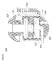
- FIG. 1A is a schematic cross-sectional diagram showing the configuration of an earphone according to Embodiment 1 of the present disclosure.
- FIG. 1B is a schematic cross-sectional diagram taken along a line A-A′ in FIG. 1A .
- FIG. 2 is a schematic cross-sectional diagram showing the configuration of another example of the earphone according to Embodiment 1 of the present disclosure.
- FIG. 3 is a schematic cross-sectional diagram showing the configuration of another example of the earphone according to Embodiment 1 of the present disclosure.
- FIG. 4 is a diagram showing sound pressure frequency characteristics relating to a first braking part according to Embodiment 1 of the present disclosure.
- FIG. 5 is a diagram showing sound pressure frequency characteristics relating to a second braking part according to Embodiment 1 of the present disclosure.
- FIG. 6 is a schematic cross-sectional diagram showing the configuration of the earphone being used, according to Embodiment 1 of the present disclosure.
- FIG. 7 is a schematic cross-sectional diagram showing the configuration of another example of the earphone according to Embodiment 1 of the present disclosure.
- FIG. 8 is a schematic cross-sectional diagram showing the configuration of an earphone according to Embodiment 2 of the present disclosure.
- FIG. 9 is a diagram showing sound pressure frequency characteristics of the earphone according to Embodiment 2 of the present disclosure.
- FIG. 10 is a schematic cross-sectional diagram showing the configuration of another example of the earphone according to Embodiment 2 of the present disclosure.
- FIG. 11 is a schematic cross-sectional diagram showing the configuration of an earphone according to Embodiment 3 of the present disclosure.
- FIG. 12 is a diagram showing sound pressure frequency characteristics of the earphone according to Embodiment 3 of the present disclosure.
- FIG. 13 is a schematic cross-sectional diagram showing the configuration of another example of the earphone according to Embodiment 3 of the present disclosure.
- FIG. 14 is a diagram showing an example of an external view of a hearing aid according to Installation Example of the present disclosure.
- FIG. 15 is a schematic cross-sectional diagram showing the configuration of the conventional earphone.
- FIG. 16 is a diagram showing the sound pressure frequency characteristics depending on presence/absence of a back surface space in the conventional earphone.
- FIG. 15 is a schematic cross-sectional diagram showing the configuration of the conventional earphone 1000 .
- the conventional earphone 1000 includes a loudspeaker unit 1001 , a housing 1002 , a sound output hole 1003 provided through the housing 1002 , and a back surface panel 1004 fitted to the housing 1002 .
- a user replaces the back surface panel 1004 of the earphone 1000 to adjust the volume of the back surface space formed by the loudspeaker unit 1001 , the housing 1002 , and the back surface panel 1004 , and thus the user can select a desired minimum resonance frequency.
- FIG. 16 is a diagram showing the sound pressure frequency characteristics depending on presence/absence of the back surface space in the conventional earphone 1000 .
- a horizontal axis represents the frequency
- a vertical axis represents the sound pressure level.
- the sound pressure frequency characteristics in the state where no back surface space is provided are represented by a solid line
- the sound pressure frequency characteristics in the state where a back surface space is provided is represented by a dotted line. It can be confirmed from FIG.
- the back surface space provided in the earphone 1000 causes the minimum resonance frequency to increase from f′0 to f0, and enables adjustment of a difference between the sound pressure level in the frequency range lower than the minimum resonance frequency f0 and the sound pressure level in the frequency range higher than the minimum resonance frequency f0.
- the above-mentioned conventional earphone 1000 has the following drawbacks.
- an undesirable peak is generated in the minimum resonance frequency f0.
- the sound pressure level becomes constant, and therefore, the sound pressure frequency characteristics in the frequency range lower than the minimum resonance frequency f0 cannot be freely adjusted.
- the inventors of the present disclosure has devised an earphone capable of suppressing a peak that occurs when the minimum resonance frequency increases, and freely adjusting the sound pressure frequency characteristics in the frequency range lower than the minimum resonance frequency.
- An earphone includes: a loudspeaker unit; a sound conductive tube which is connected to a front surface having a diaphragm included in the loudspeaker unit, and has a hole through which a sound generated from the loudspeaker unit is emitted; a housing which is connected to a back surface of the loudspeaker unit so that a space is formed between the housing and the back surface of the loudspeaker unit, and has a first air hole connecting the space to external air; a first braking part which closes a sound hole of the loudspeaker unit; and a second braking part which closes the first air hole.
- a peak that occurs due to increase in the minimum resonance frequency can be suppressed by the first braking part, and furthermore, a sound quality suitable for the earphone can be realized by the degree of the braking effect of the second braking part.
- the first braking part and the second braking part are made of a nonwoven fabric or a woven fabric.
- a third braking part that closes the hole of the sound conductive tube is further provided on the loudspeaker unit side of the sound conductive tube.
- a resonance can be suppressed, which occurs due to the space formed between the diaphragm and the sound conductive tube and the mass of the air inside the sound conductive tube.
- An earphone includes: a loudspeaker unit; a sound conductive tube which is connected to a surface opposite to a front surface having a diaphragm included in the loudspeaker unit, and has a hole through which a sound generated from the loudspeaker unit is emitted; a housing which is connected to a front surface of the loudspeaker unit so that a space is formed between the housing and the front surface of the loudspeaker unit, and has a first air hole connecting the space to external air; a back surface plate connected to the front surface of the loudspeaker unit, and has a second air hole; a first braking part which closes the second air hole; and a second braking part which closes the first air hole.
- a peak that occurs due to increase in the minimum resonance frequency can be suppressed by the first braking part, and furthermore, a sound quality suitable for the earphone can be realized by the degree of the braking effect of the second braking part.
- the high frequency characteristics can be improved by reducing the volume of the space formed between the diaphragm and the sound conductive tube.
- the first braking part and the second braking part are made of a nonwoven fabric or a woven fabric.
- a third braking part that closes the hole of the sound conductive tube is further provided on the loudspeaker unit side of the sound conductive tube.
- a resonance can be suppressed, which occurs due to the space formed between the diaphragm and the sound conductive tube and the mass of the air inside the sound conductive tube.
- the above-mentioned earphone may be provided in a hearing aid.
- FIG. 1A is a schematic cross-sectional view of the earphone 100 according to the present embodiment.
- FIG. 1B is a schematic cross-sectional view taken along a line A-A′ in FIG. 1A and viewed in the direction of an arrow B.
- the earphone 100 includes a sound conductive tube 101 , a loudspeaker unit 102 , a housing 103 , a first braking part 115 , and a second braking part 116 joined to the housing 103 .
- the loudspeaker unit 102 includes a yoke 104 , a magnet 105 , a plate 106 , a sound hole 107 , support members 108 each having an arch-shaped cross section, a diaphragm 109 supported by the support members 108 , a frame 110 to which the support members 108 are joined, a magnetic gap 111 produced by the yoke 104 and the plate 106 , a voice coil 112 held in the magnetic gap 111 , and a magnetic fluid 113 that fills a space between the plate 106 and the voice coil 112 in the magnetic gap 111 .
- the first braking part 115 is joined to the yoke 104 so as to close the sound hole 107
- the second braking part 116 is joined to the housing 103 so as to close a first air hole 114 provided through the housing 103 .
- a space between a lower surface of the yoke 104 and the housing 103 serves as a back surface space.
- the earphone 100 includes a plurality of support members 108 (in FIG. 1B , four support members 108 ), and the plurality of support members 108 partially support the diaphragm 109 in a vibratable manner.
- the first braking part 115 and the second braking part 116 may be made of any material, such as a braking fabric or a plurality of through-holes, so long as the braking effect can be added.
- the first braking part 115 and the second braking part 116 are made of a material such as a mesh-type nonwoven fabric or woven fabric.
- the first braking part 115 and the second braking part 116 may be made of a porous material that fills the sound hole 107 and the first air hole 114 , respectively.
- the first braking part 115 is joined to the yoke 104
- the first braking part 115 may be joined to the plate 106 as shown in FIG. 2 .
- the second braking part 116 is joined to the inside of the earphone 100 in the housing 103
- the second braking part 116 may be joined to the outside of the earphone 100 as shown in FIG. 2 .
- the first air hole 114 is provided on a bottom wall of the housing 103 .
- the first air hole 114 may be provided on a side wall of the housing 103 as shown in FIG. 3 .
- the position where the first air hole 114 is provided is not particularly limited, and the first air hole 114 may be provided at any position so long as it is not covered with an ear when the earphone 100 is inserted in the ear.
- the operation of the earphone 100 configured as described above, when it is inserted in an external auditory canal, will be described.
- the voice coil 112 vibrates in accordance with the Fleming's left hand rule. Since the voice coil 112 is joined to the diaphragm 109 , the diaphragm 109 vibrates in the same direction as the vibration of the voice coil 112 . As a result, a sound wave is generated from the diaphragm 109 .
- the compliance of the support members 108 is sufficiently high as compared to the conventional support member that encloses the entire circumference of the diaphragm 109 , and thereby the minimum resonance frequency is reduced to several hundreds of Hz.
- the loudspeaker unit 102 is joined to the housing 103 , the compliance of the earphone 100 increases, and thereby the minimum resonance frequency increases. Simultaneously with this, a peak is generated in the minimum resonance frequency. However, this peak is reduced by the acoustic braking of the first braking part 115 . Further, the sound pressure frequency characteristics in a frequency range lower than the minimum resonance frequency is determined by the acoustic braking of the second braking part 116 . The above operation will be described in detail below.
- FIG. 4 is a diagram showing the sound pressure frequency characteristics relating to the first braking part 115 of the earphone 100 according to the present embodiment.
- a horizontal axis represents the frequency
- a vertical axis represents the sound pressure level.
- the sound pressure frequency characteristics in state 1 wherein the sound conductive tube 101 side is a front side of the earphone 100 , and only a space is provided on the back surface of the loudspeaker unit 102 , is represented by a solid line.
- the sound pressure frequency characteristics in state 2 wherein a space and the first braking part 115 are provided on the back surface of the loudspeaker unit 102 , is represented by a dotted line. As shown in FIG.
- FIG. 5 is a diagram showing the sound pressure frequency characteristics relating to the second braking part 116 of the earphone 100 according to the present embodiment.
- a horizontal axis represents the frequency
- a vertical axis represents the sound pressure level.
- states 3 , 4 , and 5 represent the states where braking members A, B, and C are used as the second braking part 116 of the earphone 100 , respectively.
- the braking members A, B, and C have the braking effects in descending order.
- the braking member A provides the substantially hermetically closed state where no sound passes through the first air hole 114
- the braking members B and C provide the states where sound is more difficult to pass through the first air hole 114 in this order.
- the state 3 is represented by a solid line
- the state 4 is represented by a dotted line
- the state 5 is represented by a dashed-dotted line.
- the loudspeaker unit 102 having the low minimum resonance frequency is applied to the earphone 100 , it is possible to realize the sound pressure frequency characteristics suitable for the earphone 100 by providing the back surface space, the first braking part 115 , and the second braking part 116 .
- a braking fabric such as a mesh-type nonwoven fabric or woven fabric is used as a material of the first braking part 115 and the second braking part 116 , if the magnetic fluid 113 is scattered due to dropping impact or the like of the earphone 100 , the braking fabric absorbs the magnetic fluid 113 to prevent the magnetic fluid 113 from flowing outside the earphone 100 .
- FIG. 6 is a schematic cross-sectional diagram showing the configuration of the earphone 500 corresponding to the earphone 100 of the present embodiment which is actually used.
- the earphone 500 includes an ear chip 501 , a terminal 502 , wires 503 , and a cord 504 having the wires 503 therein.
- a hole through which the cord 504 passes, which is formed through the housing 103 is hermetically closed by a rubber plug or the like (not shown).
- the internal configuration of the earphone 500 is identical to that of the above-mentioned earphone 100 .
- the generated sound wave reaches an eardrum of the user via the sound conductive tube 101 , the ear chip 501 , and the external auditory canal, and thereby the user perceives the sound wave.
- the loudspeaker unit 102 having the low minimum resonance frequency can realize the sound pressure frequency characteristics suitable for the earphone 500 , and therefore, the user of the earphone 500 is provided with high sound quality.
- a support member 108 may be joined to the entire circumference of the diaphragm 109 .
- the magnetic fluid 113 is provided to prevent a sound wave having a phase opposite to the phase of the sound wave generated from the diaphragm 109 toward the sound conductive tube 101 , from traveling from a surface of the diaphragm 109 on the side opposite to the sound conductive tube 101 toward the sound conductive tube 101 .
- the support member 108 and the diaphragm 109 prevent a sound wave having a phase opposite to the phase of the sound wave generated from the diaphragm 109 toward the sound conductive tube 101 , from traveling from a surface of the diaphragm 109 on the side opposite to the sound conductive tube 101 toward the sound conductive tube 101 . Therefore, the magnetic fluid 113 is not an indispensable component in the present disclosure. That is, the magnetic fluid 113 may be removed from the components of the earphone 100 , and the support member 108 may be joined to the entire circumference of the diaphragm 109 .
- a third braking part 119 joined to the sound conductive tube 101 may be provided in order to suppress a resonance that occurs due to the space formed between the diaphragm 109 and the sound conductive tube 101 and the mass of the air inside the sound conductive tube 101 .
- the earphone 600 is characterized by that, in the earphone 100 of the Embodiment 1, if the sound conductive tube 101 side is an upper side, the loudspeaker unit 102 is inverted so that the diaphragm 109 faces the bottom wall of the housing 103 , and a back surface plate through which a second air hole is formed is provided inside the housing, and the first braking part is joined to the back surface plate so as to close the second air hole.
- FIG. 8 is a schematic cross-sectional view of the earphone 600 according to the present embodiment.
- the earphone 600 includes a sound conductive tube 601 , a loudspeaker unit 602 , a housing 603 , a back surface plate 617 , a first braking part 615 joined to the back surface plate 617 so as to close a second air hole 618 provided through the back surface plate 617 , and a second braking part 616 joined to the housing 603 so as to close a first air hole 614 provided through the housing 603 .
- the loudspeaker unit 602 includes a yoke 604 , a magnet 605 , a plate 606 , a sound hole 607 , support members 608 each having an arch-shaped cross section, a diaphragm 609 supported by the support members 608 , a frame 610 joined to the support members 608 , a magnetic gap 611 produced by the yoke 604 and the plate 606 , a voice coil 612 held in the magnetic gap 611 , and a magnetic fluid 613 that fills a space between the plate 606 and the voice coil 612 in the magnetic gap 611 .
- the back surface plate 617 is joined to the frame 610 .
- Embodiment 2 is greatly different from Embodiment 1 in that the sound wave having passed through the sound hole 607 travels toward the external auditory canal of the user via the sound conductive tube 601 .
- the earphone 600 thus configured realizes reduction in the volume of the space formed between the diaphragm 609 and the sound conductive tube 601 , as compared to Embodiment 1.
- the volume of a space formed between the diaphragm 609 and the sound conductive tube 601 is reduced to the volume of a space formed between the diaphragm 609 and the sound hole 607 . Since the space formed between the diaphragm 609 and the sound conductive tube 601 serves to reduce the high frequency characteristics, the high frequency characteristics can be improved in the present embodiment as compared to Embodiment 1.
- the sound conductive tube 601 side is a front side of the earphone 600
- the first braking part 615 cannot be provided in the back surface space of the loudspeaker unit 602 . Therefore, the back surface plate 617 is provided inside the housing 603 and on the back surface side of the loudspeaker unit 602 , and the first braking part 615 is joined so as to close the second air hole 618 formed through the back surface plate 617 .
- FIG. 9 is a diagram showing the sound pressure frequency characteristics of the earphone 600 according to the present embodiment.
- a horizontal axis represents the frequency
- a vertical axis represents the sound pressure level.
- the sound pressure frequency characteristics of the state 3 shown in Embodiment 1 is represented by a solid line
- the sound pressure frequency characteristics of a state 6 according to the present embodiment is shown by a dotted line.
- the first braking part 115 of the state 3 and the first braking part 615 of the state 6 are implemented by a braking member having the same braking effect
- the second braking part 116 of the state 3 and the second braking part 616 of the state 6 are implemented by a braking member having the same braking effect. It can be confirmed from FIG.
- the high frequency characteristics in the vicinity of 8 ⁇ 10 3 Hz to 1 ⁇ 10 4 Hz are increased by about 10 dB in the state 6 as compared to the state 3 . Accordingly, it is found that the high frequency characteristics can be improved by reducing the volume of the space formed between the diaphragm 609 and the sound conductive tube 601 .
- a third braking part 619 joined to the sound conductive tube 601 may be provided in order to suppress a resonance that occurs due to the space formed between the diaphragm 609 and the sound hole 607 and the mass of the air inside the sound conductive tube 601 .
- FIG. 11 is a schematic cross-sectional view of the earphone 800 according to the present embodiment.
- the earphone 800 includes a sound conductive tube 801 , a loudspeaker unit 802 , a housing 803 , and a second braking part 816 joined to the housing 803 so as to close a first air hole 814 provided through the housing 803 .
- the loudspeaker unit 802 includes a yoke 804 , a magnet 805 , a plate 806 , a sound hole 807 , support members 808 each having an arch-shaped cross section, a diaphragm 809 supported by the support members 808 , a frame 810 joined to the support members 808 , a magnetic gap 811 formed by the yoke 804 and the plate 806 , a voice coil 812 held inside the magnetic gap 811 , and a magnetic fluid 813 that fills a space between the plate 806 and the voice coil 812 in the magnetic gap 811 .
- Embodiment 2 Like Embodiment 2, an electric signal is input to the voice coil 812 , the voice coil 812 vibrates, and a sound wave is generated from the diaphragm 809 .
- Embodiment 3 is greatly different from Embodiment 2 in that the first braking part is not provided.
- the diaphragm 609 protrudes to the side opposite to the sound conductive tube 601 to reduce the volume of the space formed between the diaphragm 609 and the sound conductive tube 601 .
- Embodiment 2 In the configuration of Embodiment 2, however, the back surface plate 617 needs to be provided inside the housing 603 in order to provide the first braking part 615 . Accordingly, implementation of Embodiment 2 has a problem that the number of components increases. So, in the present embodiment, instead of providing the first braking part and the back surface plate as means to suppress a peak in the minimum resonance frequency, the viscosity of the magnetic fluid 813 is utilized, and thereby the number of components is reduced.
- FIG. 12 is a diagram showing the sound pressure frequency characteristics of the earphone 800 .
- states 7 , 8 , and 9 show the states where magnetic fluids A, B, and C are used as the magnetic fluid 813 of the earphone 800 , respectively.
- the magnetic fluids A, B, and C have the viscosities in ascending order.
- the state 7 is represented by a solid line
- the state 8 is represented by a dotted line
- the state 9 is represented by a dashed-dotted line. It is found from FIG. 12 that the peak in the minimum resonance frequency can be suppressed by increasing the viscosity of the magnetic fluid 813 .
- the peak in the minimum resonance frequency can be suppressed as in Embodiment 2 by adjusting the viscosity of the magnetic fluid 813 , and therefore, the number of components can be reduced.
- the magnetic fluid 813 is injected into the area surrounded by the plate 806 and the voice coil 812 in the magnetic gap 811
- the magnetic fluid 813 may be injected into the entirety of the magnetic gap 811 in order to enhance the braking effect.
- the braking effect can be enhanced by bringing the voice coil 812 and the plate 806 closer to each other.
- a third braking part 819 joined to the sound conductive tube 801 may be provided in order to suppress a resonance that occurs due to the space formed between the diaphragm 809 and the sound hole 807 and the mass of the air inside the sound conductive tube 801 .
- submicron holes may be formed through the housing and the back surface plate as the first air hole and the second air hole, respectively. Also in this case, it is possible to achieve the same braking effect as that achieved by the configuration including the first braking part and the second braking part.
- FIG. 14 is a diagram showing an external view of a hearing aid in which any of the earphones according to Embodiments 1 to 3 is installed.
- the hearing aid shown in FIG. 14 includes a receiver part 901 , a hearing aid body 902 , and a lead tube 903 .
- the configuration of the receiver part 901 is based on the configuration of the earphone according to any of Embodiments 1 to 3.
- the receiver part 901 since the receiver part 901 has the configuration of the earphone of the present disclosure, it is possible to provide a small-size hearing aid which causes a user to feel less discomfort when it is inserted in his/her ear, suppresses a peak that occurs when the minimum resonance frequency increases, freely adjusts the sound pressure frequency characteristics in the frequency range lower than the minimum resonance frequency, and is adaptable to various users who need different sound pressure frequency characteristics.
- the earphone using the loudspeaker unit having the low minimum resonance frequency can provide the sound pressure frequency characteristics in which the frequency range lower than the minimum resonance frequency and the frequency range higher than the minimum resonance frequency are well balanced. Thereby, high sound quality can be achieved in earphones of hearing aids, portable music players, and the like.
- the earphone according to the present disclosure is applicable to AV equipment such as hearing aids, portable music players, and the like.
Landscapes
- Physics & Mathematics (AREA)
- Engineering & Computer Science (AREA)
- Acoustics & Sound (AREA)
- Signal Processing (AREA)
- Health & Medical Sciences (AREA)
- Otolaryngology (AREA)
- General Health & Medical Sciences (AREA)
- Neurosurgery (AREA)
- Headphones And Earphones (AREA)
- Audible-Bandwidth Dynamoelectric Transducers Other Than Pickups (AREA)
Abstract
Description
- [PTL 1] Japanese Laid-Open Patent Publication No. 2008-283398
-
- 100, 500, 1000 earphone
- 101, 601 sound conductive tube
- 102, 602, 1001 loudspeaker unit
- 103, 603, 1002 housing
- 104, 604, 804 yoke
- 105, 605, 805 magnet
- 106, 606, 806 plate
- 107, 607, 807 sound hole
- 108, 608, 808 support member
- 109, 609, 809 diaphragm
- 110, 610, 810 frame
- 111, 611, 811 magnetic gap
- 112, 612, 812 voice coil
- 113, 613, 813 magnetic fluid
- 114, 614, 814 first air hole
- 115, 615 first braking part
- 116, 616, 816 second braking part
- 119, 619, 819 third braking part
- 501 ear chip
- 502 terminal
- 503 wires
- 504 cord
- 617 back surface plate
- 618 second air hole
- 901 receiver part
- 902 hearing aid body
- 903 lead tube
- 1003 sound output hole
- 1004 back surface panel
Claims (6)
Applications Claiming Priority (3)
| Application Number | Priority Date | Filing Date | Title |
|---|---|---|---|
| JP2012-016760 | 2012-01-30 | ||
| JP2012016760 | 2012-01-30 | ||
| PCT/JP2013/000471 WO2013114864A1 (en) | 2012-01-30 | 2013-01-29 | Earphone |
Publications (2)
| Publication Number | Publication Date |
|---|---|
| US20140056455A1 US20140056455A1 (en) | 2014-02-27 |
| US9319767B2 true US9319767B2 (en) | 2016-04-19 |
Family
ID=48904911
Family Applications (1)
| Application Number | Title | Priority Date | Filing Date |
|---|---|---|---|
| US14/003,892 Active US9319767B2 (en) | 2012-01-30 | 2013-01-29 | Earphone |
Country Status (4)
| Country | Link |
|---|---|
| US (1) | US9319767B2 (en) |
| EP (1) | EP2811757B1 (en) |
| JP (1) | JP6136016B2 (en) |
| WO (1) | WO2013114864A1 (en) |
Cited By (12)
| Publication number | Priority date | Publication date | Assignee | Title |
|---|---|---|---|---|
| US20170280227A1 (en) * | 2016-03-25 | 2017-09-28 | Jetvox Acoustic Corp. | Earphone device having concentrating tube |
| CN108566600A (en) * | 2018-04-27 | 2018-09-21 | 歌尔股份有限公司 | A kind of sound-producing device and electronic equipment |
| US10484775B1 (en) * | 2018-07-16 | 2019-11-19 | Eten Electroncis Limited | Earphone structure |
| US20200045402A1 (en) * | 2018-08-02 | 2020-02-06 | EVA Automation, Inc. | Headphone with Multiple Acoustic Paths |
| US20200204908A1 (en) * | 2018-12-20 | 2020-06-25 | Advanced Semiconductor Engineering, Inc. | Acoustic device |
| US20200221202A1 (en) * | 2019-01-07 | 2020-07-09 | Bose Corporation | Earphone |
| US10805713B2 (en) * | 2014-06-27 | 2020-10-13 | Apple Inc. | Mass loaded earbud with vent chamber |
| US11234066B2 (en) * | 2020-03-16 | 2022-01-25 | Almus Corp. | Earphone |
| US11240581B2 (en) * | 2018-01-23 | 2022-02-01 | Hideaki Sampei | Earpiece and earphone using the same |
| US20220103933A1 (en) * | 2019-10-08 | 2022-03-31 | Soniphi Llc | Systems & Methods For Expanding Sensation Using Headset With Isobaric Chambers |
| US20240080603A1 (en) * | 2022-09-01 | 2024-03-07 | Apple Inc. | Acoustic vent and protective membrane |
| US12244990B2 (en) | 2022-09-01 | 2025-03-04 | Apple Inc. | Acoustic vent and protective membrane |
Families Citing this family (28)
| Publication number | Priority date | Publication date | Assignee | Title |
|---|---|---|---|---|
| US9319767B2 (en) * | 2012-01-30 | 2016-04-19 | Panasonic Intellectual Property Management Co., Ltd. | Earphone |
| WO2015022817A1 (en) * | 2013-08-12 | 2015-02-19 | ソニー株式会社 | Headphone and acoustic characteristic adjustment method |
| WO2015068756A1 (en) * | 2013-11-11 | 2015-05-14 | シャープ株式会社 | Earphone system |
| WO2015076006A1 (en) | 2013-11-19 | 2015-05-28 | ソニー株式会社 | Headphone and acoustic characteristic adjustment method |
| DE102014109291B4 (en) * | 2014-07-02 | 2017-04-13 | Bachmaier Gmbh & Co. Kg | In ear headphones |
| US9661420B2 (en) * | 2014-08-19 | 2017-05-23 | Apple Inc. | Moving coil motor arrangement with a sound outlet for reducing magnetic particle ingress in transducers |
| US9628903B2 (en) | 2014-12-23 | 2017-04-18 | Bose Corporation | Microspeaker acoustical resistance assembly |
| CN104581483A (en) * | 2014-12-24 | 2015-04-29 | 青岛歌尔声学科技有限公司 | Open type earphone |
| KR20170134703A (en) | 2015-04-10 | 2017-12-06 | 플레어 오디오 테크놀로지스 리미티드 | Headphones or earphones |
| KR101767467B1 (en) * | 2016-04-19 | 2017-08-11 | 주식회사 오르페오사운드웍스 | Noise shielding earset and method for manufacturing the earset |
| JP7094015B2 (en) * | 2016-09-02 | 2022-07-01 | 東京音響株式会社 | Canal type earphone |
| TWI628961B (en) * | 2016-11-24 | 2018-07-01 | 王士俊 | Earphone for regulating pressure in ear canal and providing natural sound and manufacture method thereof |
| US10595111B2 (en) * | 2017-03-20 | 2020-03-17 | Bose Corporation | Earbud frame for acoustic driver and complimentary ear tip |
| JP6905181B2 (en) * | 2017-04-24 | 2021-07-21 | オンキヨーホームエンターテイメント株式会社 | Headphones and speaker unit |
| US20200366996A1 (en) * | 2017-10-04 | 2020-11-19 | Panasonic Intellectual Property Management Co., Ltd. | Sound output device, earphone, hearing aid, and mobile terminal device |
| WO2019077925A1 (en) | 2017-10-19 | 2019-04-25 | パナソニックIpマネジメント株式会社 | Loudspeaker and diaphragm unit |
| US10390143B1 (en) * | 2018-02-15 | 2019-08-20 | Bose Corporation | Electro-acoustic transducer for open audio device |
| US11470414B2 (en) * | 2018-09-12 | 2022-10-11 | Goertek Inc. | Earphone and method for manufacturing an earphone |
| KR102059001B1 (en) * | 2018-10-15 | 2019-12-24 | 엘지전자 주식회사 | Portable sound equipment |
| CN109862486B (en) * | 2018-12-29 | 2020-06-16 | 安克创新科技股份有限公司 | a speaker assembly |
| US11706552B2 (en) * | 2019-09-02 | 2023-07-18 | Bose Corporation | Open audio device |
| CN114902693B (en) * | 2019-12-13 | 2025-09-19 | 深圳市韶音科技有限公司 | Sound output device |
| EP4088485A1 (en) * | 2020-01-10 | 2022-11-16 | WÖLFL, Genaro | Transducer arrangements for head- and earphones |
| CN115280795A (en) * | 2020-04-30 | 2022-11-01 | 深圳市韶音科技有限公司 | Sound output device, method for adjusting sound image and method for adjusting volume |
| US11395060B2 (en) * | 2020-07-31 | 2022-07-19 | Em-Tech Co., Ltd. | Receiver having pressure equilibrium structure |
| FR3114934B1 (en) * | 2020-10-01 | 2023-03-31 | Devialet | In-ear headphones with open chambers. |
| JP7503747B2 (en) * | 2020-12-09 | 2024-06-21 | パナソニックIpマネジメント株式会社 | Speaker unit and earphones |
| CN216437469U (en) * | 2021-11-05 | 2022-05-03 | 瑞声光电科技(常州)有限公司 | Sounding device |
Citations (21)
| Publication number | Priority date | Publication date | Assignee | Title |
|---|---|---|---|---|
| US4058688A (en) * | 1975-05-27 | 1977-11-15 | Matsushita Electric Industrial Co., Ltd. | Headphone |
| JPS62141293A (en) | 1985-12-16 | 1987-06-24 | ヒルテイ・アクチエンゲゼルシヤフト | Drill for rock drill |
| US4742887A (en) * | 1986-02-28 | 1988-05-10 | Sony Corporation | Open-air type earphone |
| WO1997047117A1 (en) | 1996-06-06 | 1997-12-11 | Northern Telecom Limited | Communications terminal having a single transducer for handset and handsfree receive functionality |
| JPH11308685A (en) | 1998-04-21 | 1999-11-05 | Bose Corp | Active noise-reduction headset |
| US20060093180A1 (en) * | 2004-10-18 | 2006-05-04 | Seong Bae Kim | Magnetic circuit having dual magnets, speaker and vibration generating apparatus using the same |
| US7149323B2 (en) * | 2001-02-13 | 2006-12-12 | Matsushita Electric Industrial Co., Ltd. | Speaker |
| US20070189569A1 (en) * | 2006-01-30 | 2007-08-16 | Etymotic Research, Inc. | Insert earphone using a moving coil driver |
| US20070201717A1 (en) * | 2006-02-27 | 2007-08-30 | Ultimate Ears, Llc | Earphone ambient eartip |
| US7447308B2 (en) * | 2005-08-26 | 2008-11-04 | Jin-Chou Tsai | Low-noise transmitting receiving earset |
| JP2008283398A (en) | 2007-05-09 | 2008-11-20 | Kenwood Corp | Earphone |
| US20090285437A1 (en) * | 2008-05-19 | 2009-11-19 | Yamaha Corporation | Earphone device and sound generating apparatus equipped with the same |
| US20100166245A1 (en) | 2008-12-26 | 2010-07-01 | Yamaha Corporation | Earphone device and sound generating apparatus equipped with the same |
| JP2010283643A (en) | 2009-06-05 | 2010-12-16 | Kenta Tanaka | Earphone device |
| JP2011082702A (en) | 2009-10-05 | 2011-04-21 | Foster Electric Co Ltd | Earphone |
| JP2011182201A (en) | 2010-03-01 | 2011-09-15 | Audio Technica Corp | Earphone device |
| US8611581B2 (en) * | 2006-01-12 | 2013-12-17 | Sony Corporation | Earphone device |
| US20140056455A1 (en) * | 2012-01-30 | 2014-02-27 | Panasonic Corporation | Earphone |
| US8670586B1 (en) * | 2012-09-07 | 2014-03-11 | Bose Corporation | Combining and waterproofing headphone port exits |
| US8885866B2 (en) * | 2011-07-22 | 2014-11-11 | Panasonic Corporation | Earphone |
| US20140348372A1 (en) * | 2013-05-24 | 2014-11-27 | Bujeon Co., Ltd. | Canal Type Earphone with Pressure Equilibrium Means |
Family Cites Families (2)
| Publication number | Priority date | Publication date | Assignee | Title |
|---|---|---|---|---|
| JPS61174290U (en) * | 1985-04-18 | 1986-10-30 | ||
| JP2001025072A (en) * | 2000-01-01 | 2001-01-26 | Tokin Corp | Electroacoustic transducer for selectively generating voice and vibration |
-
2013
- 2013-01-29 US US14/003,892 patent/US9319767B2/en active Active
- 2013-01-29 JP JP2013556262A patent/JP6136016B2/en active Active
- 2013-01-29 EP EP13744295.0A patent/EP2811757B1/en active Active
- 2013-01-29 WO PCT/JP2013/000471 patent/WO2013114864A1/en not_active Ceased
Patent Citations (22)
| Publication number | Priority date | Publication date | Assignee | Title |
|---|---|---|---|---|
| US4058688A (en) * | 1975-05-27 | 1977-11-15 | Matsushita Electric Industrial Co., Ltd. | Headphone |
| JPS62141293A (en) | 1985-12-16 | 1987-06-24 | ヒルテイ・アクチエンゲゼルシヤフト | Drill for rock drill |
| US4742887A (en) * | 1986-02-28 | 1988-05-10 | Sony Corporation | Open-air type earphone |
| WO1997047117A1 (en) | 1996-06-06 | 1997-12-11 | Northern Telecom Limited | Communications terminal having a single transducer for handset and handsfree receive functionality |
| JPH11308685A (en) | 1998-04-21 | 1999-11-05 | Bose Corp | Active noise-reduction headset |
| US7149323B2 (en) * | 2001-02-13 | 2006-12-12 | Matsushita Electric Industrial Co., Ltd. | Speaker |
| US20060093180A1 (en) * | 2004-10-18 | 2006-05-04 | Seong Bae Kim | Magnetic circuit having dual magnets, speaker and vibration generating apparatus using the same |
| US7447308B2 (en) * | 2005-08-26 | 2008-11-04 | Jin-Chou Tsai | Low-noise transmitting receiving earset |
| US8611581B2 (en) * | 2006-01-12 | 2013-12-17 | Sony Corporation | Earphone device |
| US20070189569A1 (en) * | 2006-01-30 | 2007-08-16 | Etymotic Research, Inc. | Insert earphone using a moving coil driver |
| US20070201717A1 (en) * | 2006-02-27 | 2007-08-30 | Ultimate Ears, Llc | Earphone ambient eartip |
| JP2008283398A (en) | 2007-05-09 | 2008-11-20 | Kenwood Corp | Earphone |
| JP2010004513A (en) | 2008-05-19 | 2010-01-07 | Yamaha Corp | Ear phone |
| US20090285437A1 (en) * | 2008-05-19 | 2009-11-19 | Yamaha Corporation | Earphone device and sound generating apparatus equipped with the same |
| US20100166245A1 (en) | 2008-12-26 | 2010-07-01 | Yamaha Corporation | Earphone device and sound generating apparatus equipped with the same |
| JP2010283643A (en) | 2009-06-05 | 2010-12-16 | Kenta Tanaka | Earphone device |
| JP2011082702A (en) | 2009-10-05 | 2011-04-21 | Foster Electric Co Ltd | Earphone |
| JP2011182201A (en) | 2010-03-01 | 2011-09-15 | Audio Technica Corp | Earphone device |
| US8885866B2 (en) * | 2011-07-22 | 2014-11-11 | Panasonic Corporation | Earphone |
| US20140056455A1 (en) * | 2012-01-30 | 2014-02-27 | Panasonic Corporation | Earphone |
| US8670586B1 (en) * | 2012-09-07 | 2014-03-11 | Bose Corporation | Combining and waterproofing headphone port exits |
| US20140348372A1 (en) * | 2013-05-24 | 2014-11-27 | Bujeon Co., Ltd. | Canal Type Earphone with Pressure Equilibrium Means |
Non-Patent Citations (2)
| Title |
|---|
| Extended European Search Report issued Dec. 22, 2014 in corresponding European Patent Application No. 13744295.0. |
| International Search Report mailed Mar. 26, 2013 in International (PCT) Application No. PCT/JP2013/000471. |
Cited By (19)
| Publication number | Priority date | Publication date | Assignee | Title |
|---|---|---|---|---|
| US10805713B2 (en) * | 2014-06-27 | 2020-10-13 | Apple Inc. | Mass loaded earbud with vent chamber |
| US11575985B2 (en) * | 2014-06-27 | 2023-02-07 | Apple Inc. | Mass loaded earbud with vent chamber |
| US9949016B2 (en) * | 2016-03-25 | 2018-04-17 | Jetvox Acoustic Corp. | Earphone device having concentrating tube |
| US20170280227A1 (en) * | 2016-03-25 | 2017-09-28 | Jetvox Acoustic Corp. | Earphone device having concentrating tube |
| US11240581B2 (en) * | 2018-01-23 | 2022-02-01 | Hideaki Sampei | Earpiece and earphone using the same |
| CN108566600A (en) * | 2018-04-27 | 2018-09-21 | 歌尔股份有限公司 | A kind of sound-producing device and electronic equipment |
| US10484775B1 (en) * | 2018-07-16 | 2019-11-19 | Eten Electroncis Limited | Earphone structure |
| US20200045402A1 (en) * | 2018-08-02 | 2020-02-06 | EVA Automation, Inc. | Headphone with Multiple Acoustic Paths |
| US10623847B2 (en) * | 2018-08-02 | 2020-04-14 | EVA Automation, Inc. | Headphone with multiple acoustic paths |
| US10932032B2 (en) * | 2018-12-20 | 2021-02-23 | Advanced Semiconductor Engineering, Inc. | Acoustic device |
| US20200204908A1 (en) * | 2018-12-20 | 2020-06-25 | Advanced Semiconductor Engineering, Inc. | Acoustic device |
| US10993009B2 (en) * | 2019-01-07 | 2021-04-27 | Bose Corporation | Earphone |
| US20200221202A1 (en) * | 2019-01-07 | 2020-07-09 | Bose Corporation | Earphone |
| US20220103933A1 (en) * | 2019-10-08 | 2022-03-31 | Soniphi Llc | Systems & Methods For Expanding Sensation Using Headset With Isobaric Chambers |
| US11683639B2 (en) * | 2019-10-08 | 2023-06-20 | Soniphi Llc | Systems and methods for expanding sensation using headset with isobaric chambers |
| US11234066B2 (en) * | 2020-03-16 | 2022-01-25 | Almus Corp. | Earphone |
| US20240080603A1 (en) * | 2022-09-01 | 2024-03-07 | Apple Inc. | Acoustic vent and protective membrane |
| US12133038B2 (en) * | 2022-09-01 | 2024-10-29 | Apple Inc. | Acoustic vent and protective membrane |
| US12244990B2 (en) | 2022-09-01 | 2025-03-04 | Apple Inc. | Acoustic vent and protective membrane |
Also Published As
| Publication number | Publication date |
|---|---|
| WO2013114864A1 (en) | 2013-08-08 |
| EP2811757B1 (en) | 2016-05-25 |
| JP6136016B2 (en) | 2017-05-31 |
| JPWO2013114864A1 (en) | 2015-05-11 |
| US20140056455A1 (en) | 2014-02-27 |
| EP2811757A4 (en) | 2015-01-21 |
| EP2811757A1 (en) | 2014-12-10 |
Similar Documents
| Publication | Publication Date | Title |
|---|---|---|
| US9319767B2 (en) | Earphone | |
| US8098854B2 (en) | Multiple receivers with a common spout | |
| CN104067634B (en) | Speaker unit, image stereo set, portable information processing device, moving body and earphone | |
| EP2811760B1 (en) | Speaker, inner ear headphone provided with speaker, and hearing aid | |
| KR101756653B1 (en) | Noise shielding earset with acoustic filter | |
| US9131304B2 (en) | Loudspeaker and equipment including the same | |
| US12003922B2 (en) | Systems and methods for suppressing sound leakage | |
| US9191758B2 (en) | Manufacturing process for a custom fit in-ear monitor utilizing a single piece driver module | |
| KR101767467B1 (en) | Noise shielding earset and method for manufacturing the earset | |
| CN112153542A (en) | Bone conduction loudspeaker | |
| KR101937032B1 (en) | Earset with bone conduction speaker | |
| CN109952766B (en) | Loudspeaker device and reproduction device | |
| JP6399390B2 (en) | Speakers and AV equipment | |
| US12407992B2 (en) | Systems and methods for suppressing sound leakage | |
| RU2791721C1 (en) | Acoustic output device | |
| KR20200091189A (en) | Acoustic device having multiple vibration plates | |
| KR101419491B1 (en) | Vibrative type ear phone for outputting sound in multiple channel |
Legal Events
| Date | Code | Title | Description |
|---|---|---|---|
| AS | Assignment |
Owner name: PANASONIC CORPORATION, JAPAN Free format text: ASSIGNMENT OF ASSIGNORS INTEREST;ASSIGNORS:SAKAGUCHI, ATSUSHI;SAIKI, SHUJI;MATSUMURA, TOSHIYUKI;AND OTHERS;REEL/FRAME:032503/0590 Effective date: 20130820 |
|
| AS | Assignment |
Owner name: PANASONIC INTELLECTUAL PROPERTY MANAGEMENT CO., LTD., JAPAN Free format text: ASSIGNMENT OF ASSIGNORS INTEREST;ASSIGNOR:PANASONIC CORPORATION;REEL/FRAME:034194/0143 Effective date: 20141110 Owner name: PANASONIC INTELLECTUAL PROPERTY MANAGEMENT CO., LT Free format text: ASSIGNMENT OF ASSIGNORS INTEREST;ASSIGNOR:PANASONIC CORPORATION;REEL/FRAME:034194/0143 Effective date: 20141110 |
|
| STCF | Information on status: patent grant |
Free format text: PATENTED CASE |
|
| MAFP | Maintenance fee payment |
Free format text: PAYMENT OF MAINTENANCE FEE, 4TH YEAR, LARGE ENTITY (ORIGINAL EVENT CODE: M1551); ENTITY STATUS OF PATENT OWNER: LARGE ENTITY Year of fee payment: 4 |
|
| AS | Assignment |
Owner name: PANASONIC INTELLECTUAL PROPERTY MANAGEMENT CO., LTD., JAPAN Free format text: CORRECTIVE ASSIGNMENT TO CORRECT THE ERRONEOUSLY FILED APPLICATION NUMBERS 13/384239, 13/498734, 14/116681 AND 14/301144 PREVIOUSLY RECORDED ON REEL 034194 FRAME 0143. ASSIGNOR(S) HEREBY CONFIRMS THE ASSIGNMENT;ASSIGNOR:PANASONIC CORPORATION;REEL/FRAME:056788/0362 Effective date: 20141110 |
|
| MAFP | Maintenance fee payment |
Free format text: PAYMENT OF MAINTENANCE FEE, 8TH YEAR, LARGE ENTITY (ORIGINAL EVENT CODE: M1552); ENTITY STATUS OF PATENT OWNER: LARGE ENTITY Year of fee payment: 8 |