US9318758B2 - SOFC stack with temperature adapted compression force means - Google Patents

SOFC stack with temperature adapted compression force means Download PDF

Info

Publication number
US9318758B2
US9318758B2 US14/131,752 US201214131752A US9318758B2 US 9318758 B2 US9318758 B2 US 9318758B2 US 201214131752 A US201214131752 A US 201214131752A US 9318758 B2 US9318758 B2 US 9318758B2
Authority
US
United States
Prior art keywords
fuel cell
stacking direction
load
fuel
electrolyte
Prior art date
Legal status (The legal status is an assumption and is not a legal conclusion. Google has not performed a legal analysis and makes no representation as to the accuracy of the status listed.)
Expired - Fee Related, expires
Application number
US14/131,752
Other versions
US20140141351A1 (en
Inventor
Masashi Shinohara
Keiji Tsukamoto
Hideo Urata
Current Assignee (The listed assignees may be inaccurate. Google has not performed a legal analysis and makes no representation or warranty as to the accuracy of the list.)
Honda Motor Co Ltd
Original Assignee
Honda Motor Co Ltd
Priority date (The priority date is an assumption and is not a legal conclusion. Google has not performed a legal analysis and makes no representation as to the accuracy of the date listed.)
Filing date
Publication date
Application filed by Honda Motor Co Ltd filed Critical Honda Motor Co Ltd
Assigned to HONDA MOTOR CO., LTD. reassignment HONDA MOTOR CO., LTD. ASSIGNMENT OF ASSIGNORS INTEREST (SEE DOCUMENT FOR DETAILS). Assignors: SHINOHARA, MASASHI, TSUKAMOTO, KEIJI, URATA, HIDEO
Publication of US20140141351A1 publication Critical patent/US20140141351A1/en
Application granted granted Critical
Publication of US9318758B2 publication Critical patent/US9318758B2/en
Expired - Fee Related legal-status Critical Current
Adjusted expiration legal-status Critical

Links

Images

Classifications

    • HELECTRICITY
    • H01ELECTRIC ELEMENTS
    • H01MPROCESSES OR MEANS, e.g. BATTERIES, FOR THE DIRECT CONVERSION OF CHEMICAL ENERGY INTO ELECTRICAL ENERGY
    • H01M8/00Fuel cells; Manufacture thereof
    • H01M8/04Auxiliary arrangements, e.g. for control of pressure or for circulation of fluids
    • H01M8/04082Arrangements for control of reactant parameters, e.g. pressure or concentration
    • H01M8/04201Reactant storage and supply, e.g. means for feeding, pipes
    • HELECTRICITY
    • H01ELECTRIC ELEMENTS
    • H01MPROCESSES OR MEANS, e.g. BATTERIES, FOR THE DIRECT CONVERSION OF CHEMICAL ENERGY INTO ELECTRICAL ENERGY
    • H01M8/00Fuel cells; Manufacture thereof
    • H01M8/02Details
    • H01M8/0202Collectors; Separators, e.g. bipolar separators; Interconnectors
    • H01M8/0258Collectors; Separators, e.g. bipolar separators; Interconnectors characterised by the configuration of channels, e.g. by the flow field of the reactant or coolant
    • HELECTRICITY
    • H01ELECTRIC ELEMENTS
    • H01MPROCESSES OR MEANS, e.g. BATTERIES, FOR THE DIRECT CONVERSION OF CHEMICAL ENERGY INTO ELECTRICAL ENERGY
    • H01M8/00Fuel cells; Manufacture thereof
    • H01M8/10Fuel cells with solid electrolytes
    • H01M8/12Fuel cells with solid electrolytes operating at high temperature, e.g. with stabilised ZrO2 electrolyte
    • HELECTRICITY
    • H01ELECTRIC ELEMENTS
    • H01MPROCESSES OR MEANS, e.g. BATTERIES, FOR THE DIRECT CONVERSION OF CHEMICAL ENERGY INTO ELECTRICAL ENERGY
    • H01M8/00Fuel cells; Manufacture thereof
    • H01M8/24Grouping of fuel cells, e.g. stacking of fuel cells
    • H01M8/241Grouping of fuel cells, e.g. stacking of fuel cells with solid or matrix-supported electrolytes
    • H01M8/2425High-temperature cells with solid electrolytes
    • H01M8/2432Grouping of unit cells of planar configuration
    • HELECTRICITY
    • H01ELECTRIC ELEMENTS
    • H01MPROCESSES OR MEANS, e.g. BATTERIES, FOR THE DIRECT CONVERSION OF CHEMICAL ENERGY INTO ELECTRICAL ENERGY
    • H01M8/00Fuel cells; Manufacture thereof
    • H01M8/24Grouping of fuel cells, e.g. stacking of fuel cells
    • H01M8/2457Grouping of fuel cells, e.g. stacking of fuel cells with both reactants being gaseous or vaporised
    • HELECTRICITY
    • H01ELECTRIC ELEMENTS
    • H01MPROCESSES OR MEANS, e.g. BATTERIES, FOR THE DIRECT CONVERSION OF CHEMICAL ENERGY INTO ELECTRICAL ENERGY
    • H01M8/00Fuel cells; Manufacture thereof
    • H01M8/24Grouping of fuel cells, e.g. stacking of fuel cells
    • H01M8/2465Details of groupings of fuel cells
    • H01M8/247Arrangements for tightening a stack, for accommodation of a stack in a tank or for assembling different tanks
    • H01M8/248Means for compression of the fuel cell stacks
    • HELECTRICITY
    • H01ELECTRIC ELEMENTS
    • H01MPROCESSES OR MEANS, e.g. BATTERIES, FOR THE DIRECT CONVERSION OF CHEMICAL ENERGY INTO ELECTRICAL ENERGY
    • H01M8/00Fuel cells; Manufacture thereof
    • H01M8/24Grouping of fuel cells, e.g. stacking of fuel cells
    • H01M8/2465Details of groupings of fuel cells
    • H01M8/2483Details of groupings of fuel cells characterised by internal manifolds
    • HELECTRICITY
    • H01ELECTRIC ELEMENTS
    • H01MPROCESSES OR MEANS, e.g. BATTERIES, FOR THE DIRECT CONVERSION OF CHEMICAL ENERGY INTO ELECTRICAL ENERGY
    • H01M8/00Fuel cells; Manufacture thereof
    • H01M8/24Grouping of fuel cells, e.g. stacking of fuel cells
    • H01M8/2465Details of groupings of fuel cells
    • H01M8/247Arrangements for tightening a stack, for accommodation of a stack in a tank or for assembling different tanks
    • H01M8/2475Enclosures, casings or containers of fuel cell stacks
    • HELECTRICITY
    • H01ELECTRIC ELEMENTS
    • H01MPROCESSES OR MEANS, e.g. BATTERIES, FOR THE DIRECT CONVERSION OF CHEMICAL ENERGY INTO ELECTRICAL ENERGY
    • H01M8/00Fuel cells; Manufacture thereof
    • H01M8/24Grouping of fuel cells, e.g. stacking of fuel cells
    • H01M8/249Grouping of fuel cells, e.g. stacking of fuel cells comprising two or more groupings of fuel cells, e.g. modular assemblies
    • YGENERAL TAGGING OF NEW TECHNOLOGICAL DEVELOPMENTS; GENERAL TAGGING OF CROSS-SECTIONAL TECHNOLOGIES SPANNING OVER SEVERAL SECTIONS OF THE IPC; TECHNICAL SUBJECTS COVERED BY FORMER USPC CROSS-REFERENCE ART COLLECTIONS [XRACs] AND DIGESTS
    • Y02TECHNOLOGIES OR APPLICATIONS FOR MITIGATION OR ADAPTATION AGAINST CLIMATE CHANGE
    • Y02EREDUCTION OF GREENHOUSE GAS [GHG] EMISSIONS, RELATED TO ENERGY GENERATION, TRANSMISSION OR DISTRIBUTION
    • Y02E60/00Enabling technologies; Technologies with a potential or indirect contribution to GHG emissions mitigation
    • Y02E60/30Hydrogen technology
    • Y02E60/50Fuel cells
    • Y02E60/521
    • Y02E60/525

Definitions

  • the present invention relates to a fuel cell stack including a stack body formed by stacking a plurality of solid oxide fuel cells. Each of the solid oxide fuel cells is formed by stacking an electrolyte electrode assembly between separators.
  • the electrolyte electrode assembly includes an anode, a cathode, and an electrolyte interposed between the anode and the cathode.
  • SOFC solid oxide fuel cells
  • electrolyte of ion-conductive oxide such as stabilized zirconia
  • MEA electrolyte electrode assembly
  • the electrolyte electrode assembly is interposed between a pair of separators (bipolar plates).
  • separators bipolar plates
  • a predetermined numbers of the separators and the electrolyte electrode assemblies are stacked together to form a fuel cell stack.
  • the fuel cells need to be stacked together under the desired pressure. Further, in order to prevent leakage of the reactant gas such as the fuel gas and the air as much as possible, reactant gas manifolds need to be sealed reliably by applying pressure to the reactant gas manifolds in the stacking direction.
  • a flat plate type solid oxide fuel cell disclosed in Japanese Laid-Open Patent Publication No. 2006-339035 (hereinafter referred to as the conventional technique 1 ) includes a cell stack 1 a and four manifolds M 1 to M 4 provided around the cell stack 1 a .
  • a fuel gas and an oxygen-containing gas are supplied to, and discharged from each of unit cells 2 a through the manifolds M 1 to M 4 .
  • a first pressure applying mechanism 3 a applies pressure to the cell stack 1 a
  • a second pressure applying mechanism 4 a applies pressure to the manifolds M 1 to M 4
  • the first pressure applying mechanism 3 a includes a compression spring 5 a as pressure applying means
  • the second pressure applying mechanism 4 a includes a compression spring 6 a as pressure applying means.
  • a large number of units 3 b each formed by sandwiching a power generation cell 1 b between a pair of separators 2 b are stacked together.
  • an upper tightening plate 4 b and a lower tightening plate 5 b are provided.
  • a large circular hole 6 b is formed at the center of the upper tightening plate 4 b .
  • the circular hole 6 b is larger than the outer shape of the power generation cell 1 b , and a weight 7 b is placed in the circular hole 6 b.
  • the upper tightening plate 4 b and the lower tightening plate 5 b are tightened together by a plurality of bolts 8 b to apply a tightening load in the stacking direction to the units 3 b .
  • a load applied by the weight 7 b a plurality of power generating elements of the units 3 b tightly contact each other.
  • a cell stack disclosed in Japanese Laid-Open Patent Publication No. 2009-500525 (hereinafter referred to as the conventional technique 3 ) includes at least one electrochemical cell interposed between a first end plate connected to an electrically conductive bolt and a second end plate connected to another electrically conductive bolt.
  • the cell stack includes a housing, means for fixing the cell stack to this housing to support the cell stack, and means for applying a mechanical load at a constant level to the entire fuel cell stack.
  • the means for applying the load at the constant level includes at least one elastic pad inserted into a space between the cell stack and a wall of the housing.
  • the elastic pad is a silicone pad, and has insulating property.
  • the compression spring 5 a of the first pressure applying mechanism 3 a for applying the pressure to the cell stack 1 a needs to be made of ceramics material having resistance to high temperature such as silicon nitride. Therefore, the cost for producing the first pressure applying mechanism 3 a is high.
  • the compression spring 5 a since a ceramics spring is used as the compression spring 5 a , for example, the compression spring 5 a can be damaged easily. Also, heat radiation from an upper portion of the stack is large.
  • the weight 7 b is provided in the circular hole 6 b formed at the center of the upper tightening plate 4 b .
  • the fuel cell becomes considerably large and heavy as a whole.
  • the heat capacitance of the weight 7 b is large, load following capability during starting operation of the fuel cell, and during changes in the load for the fuel cell is poor. Therefore, such changes in the operation condition cannot be handled promptly.
  • the weight 7 b is made of metal having large heat conductivity, by heat transfer, heat radiation from an upper portion of the fuel cell is large.
  • the elastic pad is made of resin material such as silicone or polymer material. Therefore, heat resistance property of the material of the elastic pad is poor. Thus, the techniques of the conventional technique 3 cannot be suitably applied to, especially, the solid oxide fuel cell operated at high temperature.
  • the present invention solve the problems of this type, and an object of the present invention is to provide a fuel cell stack having simple and compact structure in which it is possible to reliably apply a desired tightening load to each of different portions in a solid oxide fuel cell, suppress heat radiation, and carry out highly efficient power generation.
  • the present invention relates to a fuel cell stack including a stack body formed by stacking a plurality of solid oxide fuel cells in a stacking direction. Each of the solid oxide fuel cells is formed by stacking an electrolyte electrode assembly between separators.
  • the electrolyte electrode assembly includes an anode, a cathode, and an electrolyte interposed between the anode and the cathode.
  • the separator includes a sandwiching section for sandwiching the electrolyte electrode assembly and a reactant gas supply section.
  • a fuel gas channel for supplying a fuel gas along an electrode surface of the anode and an oxygen-containing gas channel for supplying an oxygen-containing gas along an electrode surface of the cathode are formed separately in the sandwiching section.
  • At least a fuel gas supply passage for supplying the fuel gas to the fuel gas channel or an oxygen-containing gas supply passage for supplying the oxygen-containing gas to the oxygen-containing gas channel extends through the reactant gas supply section in the stacking direction.
  • the fuel cell stack includes a base member provided at one end of the stack body in the stacking direction, a mounting member provided at another end of the stack body in the stacking direction for applying a load to the stack body in the stacking direction, and a fuel cell support member positioned between the mounting member and the stack body.
  • the fuel cell support member includes composite material of alumina fiber and vermiculite.
  • the fuel cell support member includes a first support section for applying a load to the sandwiching section in the stacking direction at a position corresponding to the electrolyte electrode assembly, and a second support section for applying a load to the reactant gas supply section in the stacking direction.
  • the density of the first support section is smaller than the density of the second support section.
  • the alumina fiber is elastic, and has good durability at high temperature, good heat insulating property and good electrically insulating property.
  • Vermiculite has a high expansion coefficient at high temperature.
  • the composite layer has good heat resistance property, good heat insulating property, and good heat expansion property, and it becomes possible to reliably apply the desired tightening load to the stack body because the tightening load can be easily adjusted in correspondence with the change in the temperature of the fuel cell stack.
  • the stacking load applied to the fuel cell stack is stabilized, and improvement in the power generation performance is achieved.
  • thermally self-sustaining operation means suitable operation of the fuel cell only using the heat generated by the fuel cell itself, without requiring any heat supplied from the outside.
  • the density of the first support section which applies the load to the sandwiching section in the stacking direction at the position corresponding to the electrolyte electrode assembly is smaller than the density of the second sandwiching section which applies the load to the reactant gas supply section in the stacking direction.
  • the desired sealing performance of the fuel gas supply section is maintained.
  • a relatively small load enough to achieve tight contact between the electrolyte electrode assemblies and the sandwiching sections is applied to the electrolyte electrode assemblies. Therefore, damages of the electrolyte electrode assemblies can be prevented as much as possible, and power generation and current collection can be performed efficiently.
  • FIG. 1 is a perspective view schematically showing a fuel cell stack according to a first embodiment of the present invention
  • FIG. 2 is a partially-exploded perspective view showing the fuel cell stack
  • FIG. 3 is an exploded perspective view showing a solid oxide fuel cell of the fuel cell stack
  • FIG. 4 is a partially-exploded perspective view showing a fuel cell stack according to a second embodiment of the present invention.
  • FIG. 5 is a cross sectional view schematically showing the fuel cell stack
  • FIG. 6 is a cross sectional view schematically showing a fuel cell stack according to a third embodiment of the present invention.
  • FIG. 7 is a partially-exploded perspective view showing a fuel cell stack according to a fourth embodiment of the present invention.
  • FIG. 8 is a cross sectional view schematically showing the fuel cell stack
  • FIG. 9 is a cross sectional view schematically showing a fuel cell stack according to a fifth embodiment of the present invention.
  • FIG. 10 is a perspective view schematically showing a fuel cell stack according to a sixth embodiment of the present invention.
  • FIG. 11 is a partially-exploded perspective view showing the fuel cell stack
  • FIG. 12 is an exploded perspective view showing a solid oxide fuel cell of the fuel cell stack
  • FIG. 13 is a view showing a second plate of the solid oxide fuel cell
  • FIG. 14 is a plan view, partially in cross section, showing the fuel cell stack
  • FIG. 15 is a cross sectional view schematically showing a fuel cell stack according to a seventh embodiment of the present invention.
  • FIG. 16 is a cross sectional view showing a flat plate type solid oxide fuel cell disclosed in the conventional technique 1 ;
  • FIG. 17 is a cross sectional view showing a fuel cell disclosed in the conventional technique 2 .
  • a fuel cell stack 10 is formed by stacking a plurality of solid oxide fuel cells 12 in a vertical direction indicated by an arrow C.
  • the fuel cell stack 10 is used in various applications, including stationary and mobile applications.
  • the fuel cell stack 10 is mounted on a vehicle.
  • the solid oxide fuel cell 12 performs power generation by electrochemical reactions of a fuel gas (hydrogen-containing gas such as a mixed gas of hydrogen gas, methane, and carbon monoxide) and an oxygen-containing gas (air).
  • a solid oxide fuel cell 12 includes electrolyte electrode assemblies 20 .
  • Each of the electrolyte electrode assembly (MEA) 20 includes a cathode 16 , an anode 18 , and an electrolyte (electrolyte plate) 14 interposed between the cathode 16 and the anode 18 .
  • the electrolyte 14 is made of ion-conductive oxide such as stabilized zirconia.
  • the electrolyte electrode assembly 20 is an anode support type cell in which the thickness of the anode 18 is larger than the thickness of the cathode 16 and the electrolyte 14 .
  • the surface area of the cathode 16 is smaller than the surface area of the electrolyte 14 .
  • a current collector 19 is stacked on the cathode 16 .
  • the current collector 19 has substantially the same size as the cathode 16 .
  • the current collector 19 is in the form of foamed metal or metal mesh containing metal such as nickel.
  • the electrolyte electrode assembly 20 has a rectangular shape or a square shape, and a barrier layer (not shown) is provided at least at the outer edge of the electrolyte electrode assembly 20 for preventing the entry or discharge of the oxygen-containing gas and the fuel gas.
  • the solid oxide fuel cell 12 includes a single electrolyte electrode assembly 20 sandwiched between a pair of separators (interconnectors) 22 . Further, seal members 24 a , 24 b and a metal plate 25 are interposed between the separators 22 and the electrolyte electrode assembly 20 .
  • each of the separators 22 is a metal plate of, e.g., stainless alloy.
  • mica material, ceramic material or the like, i.e., crustal component material, glass material, and composite material of clay and plastic may be used for the seal members 24 a , 24 b.
  • the metal plate 25 has a frame shape.
  • An opening 25 a formed inside the metal plate 25 is larger than the cathode 16 , and smaller than the electrolyte 14 .
  • a wall around the opening 25 a of the metal plate 25 is stacked on a portion around the electrolyte 14 to have a gas sealing function between the cathode 16 and the anode 18 .
  • the separator 22 has a rectangular shape or a square shape. At one end of the separator 22 in a longitudinal direction indicated by an arrow A, a plurality of, e.g., three oxygen-containing gas supply passages 26 a are arranged in a lateral direction indicated by an arrow B. At the other end of the separator 22 in the longitudinal direction indicated by the arrow A, a plurality of, e.g., three oxygen-containing gas discharge passages 26 b are arranged in the direction indicated by the arrow B.
  • three fuel gas supply passages 28 a are arranged in the direction indicated by the arrow A.
  • three fuel gas discharge passages 28 b are arranged in the direction indicated by the arrow A.
  • three fuel gas supply passages 28 a and three fuel gas discharge passages 28 b may be provided on both sides in the longitudinal direction of the separator 22
  • three oxygen-containing gas supply passages 26 a and three oxygen-containing gas discharge passages 26 b may be provided on both sides in the lateral direction of the separator 22 .
  • the separator 22 has an oxygen-containing gas channel 30 on its surface 22 a facing the cathode 16 of the electrolyte electrode assembly 20 for supplying the oxygen-containing gas along the electrode surface of the cathode 16 .
  • the oxygen-containing gas channel 30 includes a plurality of flow grooves extending in the direction indicated by the arrow A. Both ends of the oxygen-containing gas channel 30 are terminated adjacent to the oxygen-containing gas supply passages 26 a and the oxygen-containing gas discharge passages 26 b.
  • the separator 22 has a fuel gas channel 32 on its surface 22 b facing the anode 18 of the electrolyte electrode assembly 20 for supplying a fuel gas along the electrode surface of the anode 18 .
  • the fuel gas channel 32 includes a plurality of flow grooves extending in the direction indicated by the arrow B. Both ends of the fuel gas channel 32 are connected to the fuel gas supply passages 28 a and the fuel gas discharge passages 28 b.
  • the oxygen-containing gas supply passages 26 a , the oxygen-containing gas discharge passages 26 b , the fuel gas supply passages 28 a , and the fuel gas discharge passages 28 b are formed in the seal members 24 a , 24 b .
  • Inlet connection channels 34 a for connecting the oxygen-containing gas supply passage 26 a and the oxygen-containing gas channel 30 and outlet connection channels 34 b for connecting the oxygen-containing gas discharge passage 26 b and the oxygen-containing gas channel 30 are formed in the seal member 24 a , 24 b.
  • the electrolyte electrode assembly 20 is sandwiched between the separators 22 .
  • Each of the separators 22 includes a sandwiching section 35 and a reactant gas supply section 37 .
  • the fuel gas channel 32 and the oxygen-containing gas channel 30 are provided separately on the sandwiching section 35 .
  • the oxygen-containing gas supply passage 26 a , the oxygen-containing gas discharge passage 26 b , the fuel gas supply passage 28 a , and the fuel gas discharge passage 28 b extend through the reactant gas supply section 37 in the stacking direction.
  • a plurality of the solid oxide fuel cells 12 are stacked together in the direction indicated by the arrow C to form a stack body 36 .
  • the stack body 36 is placed on a lower end plate (base member) 38 positioned at a lower end (one end) of the stack body 36 in the stacking direction indicated by the arrow C.
  • the dimensions of the lower end plate 38 in the directions indicated by the arrows A and B are larger than the dimensions of the stack body 36 in the directions indicated by the arrows A and B.
  • the oxygen-containing gas supply passages 26 a , the oxygen-containing gas discharge passages 26 b , the fuel gas supply passages 28 a , and the fuel gas discharge passages 28 b are formed in the lower end plate (see FIG. 2 ).
  • a plurality of screw holes 40 are formed along the marginal portion of the lower end plate 38 .
  • the screw holes 40 are formed adjacent four corners of the lower end plate 38 , and substantially central positions of the respective sides.
  • manifolds for supplying and discharging the oxygen-containing gas and the fuel gas are attached to the lower end plate 38 .
  • An upper end plate 42 is provided at an upper end (other end) of the stack body 36 in the stacking direction.
  • the dimensions of the upper end plate 42 in the directions indicated by the arrows A and B are the same as the dimensions of the stack body 36 in the directions indicated by the arrows A and B.
  • the upper end plate 42 is a flat rectangular or square plate.
  • a fuel cell support member 44 and a load plate (mounting member) 46 are stacked on the upper end plate 42 . Holes 48 are formed along the marginal portion of the load plate 46 , and bolts 50 are inserted into the holes 48 . The bolts 50 are screwed into the screw holes 40 of the lower end plate 38 .
  • the fuel cell support member 44 includes a first support section 44 a for applying a load to the sandwiching section 35 in the stacking direction at a position corresponding to the electrolyte electrode assemblies 20 , and a second support section 44 b for applying a load to the reactant gas supply sections 37 in the stacking direction.
  • the density of the first support section 44 a is smaller than the density of the second support section 44 b.
  • the fuel cell support member 44 includes an alumina layer 52 and a first composite layer 54 a of the first support section 44 a , and a second composite layer 54 b of the second support section 44 b .
  • the first composite layer 54 a and the second composite layer 54 b are combined together to form a rectangular shape as a whole.
  • the first composite layer 54 a corresponding to the shape of the electrolyte electrode assembly 20 is provided, and the second composite layer 54 b having a frame shape corresponding to the reactant gas supply section 37 is provided around the first composite layer 54 a.
  • the alumina layer 52 includes alumina fiber. Specifically, the alumina layer 52 is formed by impregnating crystalline alumina fiber with an organic binder for compression in the thickness direction, and removing solvent portion of the organic binder by drying.
  • the alumina layer 52 containing the alumina fiber has elasticity, good durability at high temperature and heat insulating property and electrically insulating property.
  • Each of the first composite layer 54 a and the second composite layer 54 b is made of composite material of alumina fiber and vermiculite. Specifically, each of the first composite layer 54 a and the second composite layer 54 b is formed by dispersing vermiculite particles into slurry containing crystalline alumina fiber, and produced in the same manner as the above alumina layer 52 . The amount of vermiculite contained in the first composite layer 54 a is smaller than the amount of vermiculite contained in the second composite layer 54 b.
  • the electrolyte electrode assembly 20 is made of material having a relatively small heat expansion coefficient in comparison with the bolt 50 made of nickel based heat resistant alloy, for example. Therefore, even if the bolt 50 is expanded in the axial direction, the tightening load for tightening the stack body 36 does not become significantly small due to the elasticity of the alumina layer 52 .
  • Vermiculite has property to expand to a relatively large extent at high temperature.
  • the expansion coefficient of this vermiculite is larger than the expansion coefficient of the bolt 50 . Therefore, in particular, at high temperature, the tightening load for tightening the stack body 36 does not become significantly small.
  • the load applied to the electrolyte electrode assembly 20 in the stacking direction is smaller than the load applied to the reactant gas supply section 37 in the stacking direction.
  • the alumina layer 52 is provided adjacent to the stack body 36 , i.e., adjacent to the upper end plate 42 .
  • the first composite layer 54 a and the second composite layer 54 b are provided adjacent to the load plate 46 .
  • the upper end plate 42 is stacked on the stack body 36 .
  • the load plate 46 is provided on the first and second composite layers 54 a , 54 b.
  • the bolts 50 are inserted into the respective holes 48 of the load plate 46 . Front ends of the bolts 50 are screwed into the screw holes 40 of the lower end plate 38 .
  • the load in the stacking direction is applied to the stack body 36 , and a compression load is applied to the fuel cell support member 44 .
  • the alumina layer 52 and the first and second composite layers 54 a , 54 b are compressed. After the fuel cell support member 44 applies a tightening load to generate a surface pressure required for the stack body 36 , tightening of the bolts 50 is finished, and operation of assembling the fuel cell stack 10 is completed.
  • a fuel gas e.g., hydrogen gas
  • an oxygen-containing gas e.g., air
  • the air flows vertically upward along the oxygen-containing gas supply passages 26 a.
  • the air flows through the inlet connection channels 34 a of the seal member 24 a connected to the oxygen-containing gas supply passages 26 a , and then, the air is supplied to the oxygen-containing gas channel 30 of the separator 22 .
  • the air flows through the oxygen-containing gas channel 30 in the direction indicated by the arrow A, and the air is supplied to the cathode 16 of the electrolyte electrode assembly 20 . Then, the air is discharged into the oxygen-containing gas discharge passage 26 b.
  • the fuel gas flows vertically upward along the fuel gas supply passages 28 a , and the fuel gas is supplied to the fuel gas channel 32 of the separator 22 of each solid oxide fuel cell 12 .
  • the fuel gas flows in the direction indicated by the arrow B along the fuel gas channel 32 , and the fuel gas is supplied to the anode 18 of the electrolyte electrode assembly 20 . Then, the fuel gas is discharged to the fuel gas discharge passage 28 b.
  • the fuel gas is supplied to the anode 18 , and the air is supplied to the cathode 16 .
  • oxide ions flow through the electrolyte 14 toward the anode 18 for generating electricity by electrochemical reactions.
  • the fuel cell support member 44 is interposed between the upper end plate 42 and the load plate 46 , and the fuel cell support member 44 includes the alumina layer 52 and the first and second composite layers 54 a , 54 b.
  • the first and second composite layers 54 a , 54 b include alumina fiber with elasticity, having good durability at high temperature, good heat insulating property, and good electrical insulating property. Further, the first and second composite layers 54 a , 54 b include vermiculite having a high heat expansion coefficient at high temperature. Therefore, the first and second composite layers 54 a , 54 b has good heat resistance property, good heat insulating property, and good heat expansion property, and it becomes possible to reliably apply the desired tightening load to the stack body 36 because the tightening load can be easily adjusted in correspondence with the change in the temperature of the fuel cell stack 10 . Thus, the stacking load applied to the fuel cell stack 10 is stabilized, and improvement in the power generation performance is achieved.
  • the bolt 50 is made of material having a large linear expansion coefficient such as nickel based heat resistant alloy.
  • the heat expansion of the bolt 50 is considerably large in comparison with the electrolyte electrode assembly 20 . Therefore, at high temperature, the bolt 50 is expanded in the stacking direction to a greater extent in comparison with the stack body 36 . Therefore, the tightening load applied to the stack body 36 tends to be small.
  • the density of the first support section 44 a for applying a desired load P 1 to the sandwiching sections 35 in the stacking direction at the position corresponding to the electrolyte electrode assemblies 20 is smaller than the density of the second support section 44 b for supplying the desired load P 2 (P 1 ⁇ P 2 ) to the reactant gas supply sections 37 in the stacking direction.
  • thermally self-sustaining operation means suitable operation of the fuel cell only using the heat generated by the fuel cell, without requiring any heat supplied from the outside.
  • the desired tightening load is reliably applied to each of different portions of the solid oxide fuel cell 12 , and heat radiation is suppressed. Accordingly, it becomes possible to provide the fuel cell stack 10 which carries out highly efficient power generation.
  • the amount of vermiculite contained in the first composite layer 54 a of the first support section 44 a is smaller than the amount of vermiculite contained in the second composite layer 54 b of the second support section 44 b .
  • the expansion coefficient of the first support section 44 a is small in comparison with the second support section 44 b .
  • no excessive load is applied to the electrolyte electrode assemblies 20 .
  • tight contact between the electrolyte electrode assemblies 20 and the separators 22 is achieved desirably. Further, damages of the electrolyte electrode assemblies 20 can be prevented as much as possible, and power generation and current collection can be performed efficiently.
  • the fuel cell support member 44 includes the alumina layer 52 made of alumina fiber, and the first composite layer 54 a and the second composite layer 54 b made of composite material.
  • the alumina layer 52 is provided adjacent to the stack body 36 .
  • the first composite layer 54 a and the second composite layer 54 b are provided adjacent to the load plate 46 .
  • the alumina fiber is elastic, and has good heat durability at high temperature. Further, alumina fiber has good heat insulating property and good electrical insulating property. Therefore, the alumina layer 52 can be suitably provided at the end of the stack body 36 operated at high temperature.
  • vermiculite has poor durability at high temperature in comparison with alumina fiber
  • vermiculite has a high heat expansion coefficient at high temperature. Therefore, by providing the first composite layer 54 a and the second composite layer 54 b adjacent to the load plate 46 , vermiculite is not directly exposed to the hot stack body 36 . Further, since vermiculite is expanded by heat, the tightening load applied by the first composite layer 54 a and the second composite layer 54 b can be easily adjusted in correspondence with the change in the temperature of the fuel cell stack 10 . Thus, it becomes possible to reliably apply the desired tightening load to the stack body 36 .
  • the load plate 46 is a plate member provided in parallel with the lower end plate 38 .
  • the load plate 46 and the lower end plate 38 are tightly fastened in the stacking direction by the bolts 50 .
  • electrolyte electrode assembly 20 is an anode support type cell in which the thickness of the anode 18 is larger than the thickness of the cathode 16 and the electrolyte 14 .
  • the surface area of the cathode 16 is smaller than the surface area of the electrolyte 14 .
  • anode support type cell as the electrolyte electrode assemblies 20
  • At least the surface area of the anode 18 or the surface area of the cathode 16 may be smaller than the surface area of the electrolyte 14 .
  • the fuel cell stack 10 is formed by stacking the solid oxide fuel cells 12 in the form of flat plates. Therefore, in particular, the solid oxide fuel cells 12 can be used effectively for high temperature fuel cells such as the flat plate type solid oxide fuel cells.
  • FIG. 4 is a partially-exploded perspective view showing a fuel cell stack 60 according to a second embodiment of the present invention.
  • the constituent elements that are identical to those of the fuel cell stack 10 according to the first embodiment are labeled with the same reference numerals, and description thereof will be omitted. Also in a third and other embodiments as described later, the constituent elements that are identical to those of the fuel cell stack 10 according to the first embodiment are labeled with the same reference numerals, and description thereof will be omitted. In second and other embodiments described later, boxes are used as mounting members. However, the present invention is not limited in this respect.
  • the load plate 46 and the bolts 50 according to the first embodiment may be adopted as well in the second and other embodiments.
  • the fuel cell stack 60 includes a box 62 instead of the load plate 46 according to the first embodiment.
  • the box 62 is made of ferrite stainless material.
  • a flange 64 protruding to the outside is provided, and a plurality of holes 66 are formed in the flange 64 .
  • the stack body 36 is provided on the lower end plate through a seal member 68 .
  • the seal member 68 has a frame shape, and a plurality of holes 70 are formed in the seal member 68 coaxially with the holes 66 .
  • Bolts 72 are inserted into the holes 66 , 70 , and the bolts 72 are screwed into the screw holes 40 of the lower end plate 38 such that the bottom (mounting member) 62 a of the box 62 presses the fuel cell support member 44 in the stacking direction.
  • the heat expansion coefficient of vermiculite of the first and second composite layers 54 a , 54 b is larger than the heat expansion coefficient of the box 62 . Therefore, it becomes possible to suitably suppress reduction in the tightening load applied to the stack body 36 due to the expansion of the box 62 at high temperature.
  • the same advantages as in the case of the first embodiment are obtained. For example, the desired tightening load is reliably applied to each of the desired portions of the stack body 36 , and improvement in the power generation performance of the entire fuel cell stack 60 is achieved easily.
  • the box 62 is made of ferrite stainless material.
  • the ferrite stainless material is inexpensive, and has a small linear expansion coefficient. Therefore, the difference in the heat expansion between the box 62 and the stack body 36 becomes small, and further reduction in the load at high temperature is achieved. Moreover, the amount of heat resistant alloy used for the fuel cell stack 60 can be reduced, and the fuel cell stack 60 can be produced economically.
  • FIG. 6 is a cross sectional view schematically showing a fuel cell stack 80 according to a third embodiment of the present invention.
  • the fuel cell stack 80 does not use the alumina layer 52 .
  • Composite material made up of the first composite layer 54 a and the second composite layer 54 b ) is directly placed on the upper end plate 42 .
  • the same advantages as in the case of the second embodiment are obtained.
  • the alumina layer 52 may not be provided also in the first embodiment. In fourth and other embodiments as described later, the alumina layer 52 may not be provided as well.
  • FIG. 7 is a partial exploded perspective view showing a fuel cell stack 90 according to a fourth embodiment of the present invention.
  • the fuel cell support member 92 includes a first support section 92 a for applying a load to the sandwiching sections 35 in the stacking direction at a position corresponding to the electrolyte electrode assemblies 20 , and a second support section 92 b for applying a load to the reactant gas supply sections 37 in the stacking direction.
  • the density of the first support section 92 a is smaller than the density of the second support section 92 b.
  • the first support section 92 a includes a first composite layer 94 a corresponding to the shape of the electrolyte electrode assembly 20 .
  • the second support section 92 b contains the first composite layer 94 a , and includes two frame shaped second composite layers 94 b corresponding to the reactant gas supply section 37 .
  • the first composite layer 94 a and the second composite layers 94 b have different heights.
  • the first composite layer 94 a and the two second composite layers 94 b are compressed to have the same thickness. That is, the first composite layer 94 a applies a desired load P 1 to the sandwiching sections 35 in the stacking direction at the position corresponding to the electrolyte electrode assemblies 20 .
  • the second composite layers 94 b compressed to a greater extent in comparison with the first composite layer 94 a applies a desired load P 2 (P 1 ⁇ P 2 ) to the reactant gas supply sections 37 in the stacking direction.
  • the density of the first support section 92 a which applies the desired load P 1 to the sandwiching sections 35 in the stacking direction at the position corresponding to the electrolyte electrode assemblies 20 is smaller than the density of the second support section 92 b which applies the desired load P 2 (P 1 ⁇ P 2 ) to the reactant gas supply sections 37 in the stacking direction.
  • the same advantages as in the cases of the first to third embodiments are obtained.
  • the desired tightening load is reliably applied to each of different portions of the solid oxide fuel cell 12 , and heat radiation is suppressed. Accordingly, it becomes possible to carry out highly efficient power generation.
  • the two composite layers 94 b are stacked together to form a stack. Instead of using the two composite layers 94 b , three or more composite layers may be stacked together to form a stack, or only one thick composite layer may be used.
  • FIG. 9 is a cross sectional view schematically showing a fuel cell stack 100 according to a fifth embodiment of the present invention.
  • the fuel cell stack 100 includes a box 102 .
  • a fuel cell support member 104 is provided in the box 102 .
  • a recess 102 b corresponding to the shape of the electrolyte electrode assembly 20 is formed at the bottom 102 a of the box 102 .
  • the bottom 102 a and the recess 102 b form a mounting member.
  • the fuel cell support member 104 includes a first support section 104 a for applying a load to the sandwiching sections 35 in the stacking direction at the position corresponding to the electrolyte electrode assemblies 20 and a second support section 104 b for applying a load to the reactant gas supply sections 37 in the stacking direction.
  • the density of the first support section 104 a is smaller than the density of the second support section 104 b.
  • the first support section 104 a includes a first composite layer 106 a
  • the second support section 104 b includes a second composite layer 106 b .
  • the first composite layer 106 a and the second composite layer 106 b have the same height.
  • the first composite layer 106 a and the second composite layer 106 b are compressed to have different thicknesses.
  • the first composite layer 106 a is placed in the recess 102 b of the box 102 , the first composite layer 106 a is compressed to a smaller extent in comparison with the second composite layer 106 b , and the density of the first support section 104 a is smaller than the density of the second support section 104 b.
  • the first composite layer 106 a applies a desired load P 1 to the sandwiching sections 35 in the stacking direction at the position corresponding to the electrolyte electrode assemblies 20
  • the second composite layer 106 b applies a desired load P 2 (P 1 ⁇ P 2 ) to the reactant gas supply sections 37 in the stacking direction.
  • the density of the first support section 104 a which applies the desired load P 1 to the sandwiching sections 35 in the stacking direction at the position corresponding to electrolyte electrode assemblies 20 is smaller than the density of the second support section 104 b which applies the desired load P 2 (P 1 ⁇ P 2 ) to the reactant gas supply sections 37 in the stacking direction.
  • the same advantages as in the cases of the first to fourth embodiments are obtained.
  • the desired tightening load is reliably applied to each of different portions of the solid oxide fuel cell 12 , and heat radiation is suppressed. Accordingly, it becomes possible to carry out highly efficient power generation.
  • FIG. 10 is a perspective view schematically showing a fuel cell stack 110 according to a sixth embodiment of the present invention.
  • the fuel cell stack 110 includes a plurality of solid oxide fuel cells 112 stacked in a direction indicated by an arrow C.
  • a plurality of the solid oxide fuel cells 112 are stacked in a vertical direction indicated by the arrow C together to form a stack body 114 .
  • the solid oxide fuel cell 112 includes a pair of separators 116 sandwiching two electrolyte electrode assemblies 20 positioned in the same plane.
  • the electrolyte electrode assemblies 20 comprise anode support type cells or electrolyte support type cells.
  • the separator 116 includes a first plate 118 and a second plate 120 .
  • the first plate 118 and the second plate 120 are metal plates of stainless alloy or the like, and are joined to each other, e.g., by brazing, diffusion bonding, or laser welding.
  • the separator 116 has a fuel gas supply section (reactant gas supply section) 124 , and a fuel gas supply passage 122 extends through the center of the fuel gas supply section 124 .
  • a pair of bridge sections 126 A, 126 B are connected to the fuel gas supply section 124 , and the bridge sections 126 A, 126 B extend in directions opposite to each other.
  • Sandwiching sections 128 A, 128 B are provided integrally with the pair of bridge sections 126 A, 126 B at symmetrical positions with respect to the fuel gas supply section 124 positioned at the center.
  • the first plate 118 includes a first circular disk 130 , and the fuel gas supply passage 122 extends through the first circular disk 130 .
  • First long plates 132 A, 132 B are provided integrally with the first circular disk 130 .
  • the first long plates 132 A, 132 B extend from the first circular disk 130 in directions opposite to each other.
  • First rectangular sections 134 A, 134 B are provided integrally with the first long plates 132 A, 132 B.
  • a plurality of protrusions 136 A, 136 B are formed on surfaces of the first rectangular sections 134 A, 134 B facing the cathodes 16 .
  • Oxygen-containing gas channels 30 A, 30 B are formed by the protrusions 136 A, 136 B, respectively.
  • the second plate 120 has a second circular disk 138 , and the fuel gas supply passage 122 extends through the center of the second circular disk 138 .
  • Second long plates 140 A, 140 B are provided integrally with the second circular disk 138 , and the second long plates 140 A, 140 B extend from the second circular disk 138 in directions opposite to each other.
  • Second rectangular sections 142 A, 142 B are provided integrally with the second long plates 140 A, 140 B, respectively.
  • Fuel gas supply channels 144 A, 144 B are formed to extend from the second long plates 140 A, 140 B to the second rectangular sections 142 A, 142 B. Fuel gas inlets 146 A, 146 B are formed at positions where the fuel gas supply channels 144 A, 144 B are terminated. A plurality of fuel gas outlets 147 A, 147 B are formed on surfaces of the second rectangular sections 142 A, 142 B where the fuel gas supply channels 144 A, 144 B are formed.
  • a plurality of protrusions 148 A, 148 B are formed on surfaces of the second rectangular sections 142 A, 142 B which contact the anodes 18 .
  • Fuel gas channels 32 A, 32 B are formed by the protrusions 148 A, 148 B.
  • the fuel gas channels 32 A, 32 B are surrounded by outer protrusions 150 A, 150 B, and through holes 152 A, 152 B connected to the fuel gas outlets 147 A, 147 B are formed in the fuel gas channels 32 A, 32 B.
  • V-shaped detour path forming walls 154 A, 154 B are formed between the fuel gas inlets 146 A, 146 B and the fuel gas outlets 147 A, 147 B, respectively.
  • oxygen-containing gas supply passages 156 are formed on both sides of the bridge sections 126 A, 126 B for supplying an oxygen-containing gas in the direction indicated by the arrow C.
  • the oxygen-containing gas flows vertically upward, and the oxygen-containing gas is supplied along the oxygen-containing gas channels 30 A, 30 B of each solid oxide fuel cell 112 in the direction indicated by the arrow A.
  • an insulating seal 158 for sealing the fuel gas supply passage 122 is provided in each space between the fuel gas supply sections 124 .
  • mica material, ceramic material or the like, i.e., crustal component material, glass material, and composite material of clay and plastic may be used for the insulating seal 158 .
  • exhaust gas discharge passages 160 are formed around the sandwiching sections 128 A, 128 B, on the outside in the direction indicated by the arrow A.
  • the fuel gas and the oxygen-containing gas partially consumed in the reaction in the electrolyte electrode assembly 20 are discharged as the exhaust gas from the exhaust gas discharge passages 160 in the stacking direction.
  • the fuel cell stack 110 includes a lower end plate 162 provided at a lower end (one end) in the stacking direction of the stack body 114 , upper end plates 164 A, 164 B provided at positions corresponding to the sandwiching sections 128 A, 128 B, at an upper end (the other end) of the stack body 114 in the stacking direction, and a fuel seal plate 166 provided at a position corresponding to the fuel gas supply section 124 .
  • First support members 170 A, 170 B are placed on the upper end plates 164 A, 164 B, and a second support member 171 is positioned on the fuel seal plate 166 . These components form the fuel cell support member as a whole.
  • the second support member 171 includes an alumina layer 172 adjacent to the fuel seal plate 166 , and composite layers 174 a , 174 b stacked on the alumina layer 172 .
  • the alumina layer 172 and the composite layers 174 a , 174 b have a circular disk shape corresponding to the fuel seal plate 166 .
  • the first support members 170 A, 170 B include alumina layers 52 A, 52 B placed on the upper end plates 164 A, 164 B, and composite layers 54 A, 54 B stacked on the alumina layers 52 A, 52 B.
  • the alumina layers 172 , 52 A, 52 B have structure identical to that of the alumina layer 52 .
  • the composite layers 174 a , 174 b , 54 A, 54 B have structure identical to that of the first composite layer 54 a.
  • the second support member 171 includes two composite layers 174 a , 174 b , for allowing a large load to be applied in the stacking direction indicated by the arrow C, in comparison with the first support members 170 A, 170 B.
  • the overall thickness of the composite layers 174 a , 174 b is larger than the thickness of each of the composite layers 54 A, 54 B.
  • the fuel cell stack 110 has a box 176 , and a flange 178 is formed at an end of the opening of the box 176 , and a seal member 180 is interposed between the flange 178 and the lower end plate 162 .
  • the flange 178 and the lower end plate 162 are fixed together using a plurality of bolts 72 .
  • two air holes 182 a and two air holes 182 b connected to the oxygen-containing gas supply passage 156 , and two exhaust gas holes 184 a , 184 b connected to the exhaust gas discharge passages 160 are formed in the lower end plate 162 . Further, one fuel gas hole 185 connected to the fuel gas supply passage 122 is formed in the lower end plate 162 .
  • a fuel gas is supplied from the fuel gas hole 185 of the lower end plate 162 into the fuel gas supply passage 122 of the fuel cell stack 110 .
  • the air is supplied from the air holes 182 a , 182 b of the lower end plate 162 into the oxygen-containing gas supply passage 156 of the fuel cell stack 110 .
  • the fuel gas supplied to the fuel gas supply passage 122 is supplied into the fuel gas supply channels 144 A, 144 B formed in the bridge sections 126 A, 126 B.
  • the fuel gas from the fuel gas supply channels 144 A, 144 B flows through the fuel gas inlets 146 A, 146 B into the fuel gas channels 32 A, 32 B.
  • the fuel gas supplied to the fuel gas channels 32 A, 32 B flows through the fuel gas channels 32 A, 32 B, and the fuel gas is supplied to the anodes 18 of the electrolyte electrode assemblies 20 . Then, the fuel gas is discharged into the exhaust gas discharge passages 160 through the fuel gas outlets 147 A, 147 B.
  • the air supplied to the oxygen-containing gas supply passages 156 flows into the oxygen-containing gas channels 30 A, 30 B formed between the cathodes 16 of the electrolyte electrode assemblies 20 and the separator 116 . Then, the oxygen-containing gas moves through the oxygen-containing gas channels 30 A, 30 B in the direction indicated by the arrow A, and supplied to the cathodes 16 of the electrolyte electrode assemblies 20 . Then, the oxygen-containing gas is discharged into the exhaust gas discharge passage 160 .
  • the second support member 171 for applying a load to the fuel gas supply section 124 in the stacking direction and the first support members 170 A, 170 B for applying a load to each of the sandwiching sections 128 A, 128 B corresponding to the electrolyte electrode assemblies 20 , in the stacking direction are provided.
  • the second support member 171 applies a large load in the stacking direction, in comparison with the first support members 170 A, 170 B.
  • the second support member 171 includes composite layers 174 a , 174 b
  • the first support members 170 A, 170 B include composite layers 54 A, 54 B.
  • the overall thickness of the composite layers 174 a , 174 b is larger than the thickness of each of the composite layers 54 A, 54 B.
  • the composite layers 174 a , 174 b are compressed to a greater extent in comparison with the composite layers 54 A, 54 B. Therefore, a relatively large load is applied to the fuel gas supply sections 124 . Thus, the sealing performance of the fuel gas supply section 124 is maintained suitably.
  • the same advantages as in the cases of the first to fifth embodiments are obtained.
  • the desired tightening load is reliably applied to each of different portions of the solid oxide fuel cell 112 , and heat radiation is suppressed. Accordingly, it becomes possible to carry out highly efficient power generation.
  • FIG. 15 is a cross sectional view schematically showing a fuel cell stack 190 according to a seventh embodiment of the present invention.
  • the fuel cell stack 190 includes a box 192 .
  • first support members 170 A, 170 B of a fuel cell support member are provided on upper end plates 164 A, 164 B.
  • a second support section 194 of the fuel cell support member is provided on a fuel seal plate 166 .
  • An expansion 192 b corresponding to the shape of the electrolyte electrode assembly 20 is formed at a bottom 192 a of a box 192 , and the bottom 192 a and the expansion 192 b form a mounting member.
  • the second support section 194 includes a composite layer 174 .
  • the thickness of the composite layer 174 is the same as the thickness of each of the composite layers 54 A, 54 B.
  • the composite layer 174 and the composite layers 54 A, 54 B are compressed to have different thicknesses.
  • the composite layer 174 is placed below the expansion 192 b of the box 192 , the composite layer 174 is compressed to a greater extent, and the density of the first support members 170 A, 170 B is smaller than the density of the second support section 194 .
  • the composite layers 54 A, 54 B apply a desired load P 1 to the sandwiching sections 128 A, 128 B in the stacking direction at the positions corresponding to the electrolyte electrode assemblies 20 , and the composite layer 174 applies a desired load P 2 (P 1 ⁇ P 2 ) to the reactant gas supply sections 124 in the stacking direction.
  • the desired tightening load is reliably applied to each of different portions of the solid oxide fuel cell 112 , and heat radiation is suppressed. Accordingly, it becomes possible to carry out highly efficient power generation.

Landscapes

  • Life Sciences & Earth Sciences (AREA)
  • Engineering & Computer Science (AREA)
  • Manufacturing & Machinery (AREA)
  • Sustainable Development (AREA)
  • Sustainable Energy (AREA)
  • Chemical & Material Sciences (AREA)
  • Chemical Kinetics & Catalysis (AREA)
  • Electrochemistry (AREA)
  • General Chemical & Material Sciences (AREA)
  • Fuel Cell (AREA)
  • Inert Electrodes (AREA)

Abstract

A fuel cell stack includes a lower end plate for placing a stack body on the lower end plate, a load plate for applying a load to the stack body in a stacking direction, and a fuel cell support member provided between the load plate and the stack body. The fuel cell support member includes composite layers made of composite material of alumina fiber and vermiculite. The fuel cell support member includes a first support section for applying a load to sandwiching sections at a position corresponding to electrolyte electrode assemblies, and a second support section for applying a load to reactant gas supply sections in the stacking direction. The density of the first support section is smaller than the density of the second support section.

Description

TECHNICAL FIELD
The present invention relates to a fuel cell stack including a stack body formed by stacking a plurality of solid oxide fuel cells. Each of the solid oxide fuel cells is formed by stacking an electrolyte electrode assembly between separators. The electrolyte electrode assembly includes an anode, a cathode, and an electrolyte interposed between the anode and the cathode.
BACKGROUND ART
Typically, solid oxide fuel cells (SOFC) employ an electrolyte of ion-conductive oxide such as stabilized zirconia. The electrolyte is interposed between an anode and a cathode to form an electrolyte electrode assembly (MEA). The electrolyte electrode assembly is interposed between a pair of separators (bipolar plates). In use, generally, a predetermined numbers of the separators and the electrolyte electrode assemblies are stacked together to form a fuel cell stack.
In a fuel cell stack, in order to obtain the output voltage efficiently, the fuel cells need to be stacked together under the desired pressure. Further, in order to prevent leakage of the reactant gas such as the fuel gas and the air as much as possible, reactant gas manifolds need to be sealed reliably by applying pressure to the reactant gas manifolds in the stacking direction.
In this regard, for example, as shown in FIG. 16, a flat plate type solid oxide fuel cell disclosed in Japanese Laid-Open Patent Publication No. 2006-339035 (hereinafter referred to as the conventional technique 1) includes a cell stack 1 a and four manifolds M1 to M4 provided around the cell stack 1 a. A fuel gas and an oxygen-containing gas are supplied to, and discharged from each of unit cells 2 a through the manifolds M1 to M4.
A first pressure applying mechanism 3 a applies pressure to the cell stack 1 a, and a second pressure applying mechanism 4 a applies pressure to the manifolds M1 to M4. The first pressure applying mechanism 3 a includes a compression spring 5 a as pressure applying means, and the second pressure applying mechanism 4 a includes a compression spring 6 a as pressure applying means.
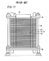
Further, in a fuel cell disclosed in Japanese Laid-Open Patent Publication No. 2007-073359 (hereinafter referred to as the conventional technique 2), as shown in FIG. 17, a large number of units 3 b each formed by sandwiching a power generation cell 1 b between a pair of separators 2 b are stacked together. At both ends (upper and lower ends) in the stacking direction of the fuel cell, an upper tightening plate 4 b and a lower tightening plate 5 b are provided. A large circular hole 6 b is formed at the center of the upper tightening plate 4 b. The circular hole 6 b is larger than the outer shape of the power generation cell 1 b, and a weight 7 b is placed in the circular hole 6 b.
The upper tightening plate 4 b and the lower tightening plate 5 b are tightened together by a plurality of bolts 8 b to apply a tightening load in the stacking direction to the units 3 b. By a load applied by the weight 7 b, a plurality of power generating elements of the units 3 b tightly contact each other.
Further, a cell stack disclosed in Japanese Laid-Open Patent Publication No. 2009-500525 (PCT) (hereinafter referred to as the conventional technique 3) includes at least one electrochemical cell interposed between a first end plate connected to an electrically conductive bolt and a second end plate connected to another electrically conductive bolt.
The cell stack includes a housing, means for fixing the cell stack to this housing to support the cell stack, and means for applying a mechanical load at a constant level to the entire fuel cell stack. The means for applying the load at the constant level includes at least one elastic pad inserted into a space between the cell stack and a wall of the housing. For example, the elastic pad is a silicone pad, and has insulating property.
SUMMARY OF INVENTION
In the conventional technique 1, the operating temperature of the fuel cell is considerably high. Therefore, the compression spring 5 a of the first pressure applying mechanism 3 a for applying the pressure to the cell stack 1 a needs to be made of ceramics material having resistance to high temperature such as silicon nitride. Therefore, the cost for producing the first pressure applying mechanism 3 a is high.
Further, since a ceramics spring is used as the compression spring 5 a, for example, the compression spring 5 a can be damaged easily. Also, heat radiation from an upper portion of the stack is large.
Further, in the conventional technique 2, the weight 7 b is provided in the circular hole 6 b formed at the center of the upper tightening plate 4 b. In the structure, the fuel cell becomes considerably large and heavy as a whole.
Further, since the heat capacitance of the weight 7 b is large, load following capability during starting operation of the fuel cell, and during changes in the load for the fuel cell is poor. Therefore, such changes in the operation condition cannot be handled promptly. Moreover, since the weight 7 b is made of metal having large heat conductivity, by heat transfer, heat radiation from an upper portion of the fuel cell is large.
Further, in the conventional technique 3, the elastic pad is made of resin material such as silicone or polymer material. Therefore, heat resistance property of the material of the elastic pad is poor. Thus, the techniques of the conventional technique 3 cannot be suitably applied to, especially, the solid oxide fuel cell operated at high temperature.
The present invention solve the problems of this type, and an object of the present invention is to provide a fuel cell stack having simple and compact structure in which it is possible to reliably apply a desired tightening load to each of different portions in a solid oxide fuel cell, suppress heat radiation, and carry out highly efficient power generation.
The present invention relates to a fuel cell stack including a stack body formed by stacking a plurality of solid oxide fuel cells in a stacking direction. Each of the solid oxide fuel cells is formed by stacking an electrolyte electrode assembly between separators. The electrolyte electrode assembly includes an anode, a cathode, and an electrolyte interposed between the anode and the cathode.
In the fuel cell stack, the separator includes a sandwiching section for sandwiching the electrolyte electrode assembly and a reactant gas supply section. A fuel gas channel for supplying a fuel gas along an electrode surface of the anode and an oxygen-containing gas channel for supplying an oxygen-containing gas along an electrode surface of the cathode are formed separately in the sandwiching section. At least a fuel gas supply passage for supplying the fuel gas to the fuel gas channel or an oxygen-containing gas supply passage for supplying the oxygen-containing gas to the oxygen-containing gas channel extends through the reactant gas supply section in the stacking direction.
The fuel cell stack includes a base member provided at one end of the stack body in the stacking direction, a mounting member provided at another end of the stack body in the stacking direction for applying a load to the stack body in the stacking direction, and a fuel cell support member positioned between the mounting member and the stack body. The fuel cell support member includes composite material of alumina fiber and vermiculite.
The fuel cell support member includes a first support section for applying a load to the sandwiching section in the stacking direction at a position corresponding to the electrolyte electrode assembly, and a second support section for applying a load to the reactant gas supply section in the stacking direction. The density of the first support section is smaller than the density of the second support section.
According to the present invention, the alumina fiber is elastic, and has good durability at high temperature, good heat insulating property and good electrically insulating property. Vermiculite has a high expansion coefficient at high temperature. Thus, the composite layer has good heat resistance property, good heat insulating property, and good heat expansion property, and it becomes possible to reliably apply the desired tightening load to the stack body because the tightening load can be easily adjusted in correspondence with the change in the temperature of the fuel cell stack. Thus, the stacking load applied to the fuel cell stack is stabilized, and improvement in the power generation performance is achieved.
Further, heat radiation from the fuel cell stack is suitably suppressed, and thermally self-sustaining operation can be facilitated. The thermally self-sustaining operation herein means suitable operation of the fuel cell only using the heat generated by the fuel cell itself, without requiring any heat supplied from the outside.
Further, the density of the first support section which applies the load to the sandwiching section in the stacking direction at the position corresponding to the electrolyte electrode assembly is smaller than the density of the second sandwiching section which applies the load to the reactant gas supply section in the stacking direction. In the structure, since a relatively large load is applied to the fuel gas supply section, the desired sealing performance of the fuel gas supply section is maintained. In the meanwhile, a relatively small load enough to achieve tight contact between the electrolyte electrode assemblies and the sandwiching sections is applied to the electrolyte electrode assemblies. Therefore, damages of the electrolyte electrode assemblies can be prevented as much as possible, and power generation and current collection can be performed efficiently.
Thus, it becomes possible to provide a fuel cell stack having simple and compact structure in which it is possible to reliably apply respective desired tightening loads to different portions in a solid oxide fuel cell, and suppress heat radiation for achieving highly efficient operation.
BRIEF DESCRIPTION OF DRAWINGS
FIG. 1 is a perspective view schematically showing a fuel cell stack according to a first embodiment of the present invention;
FIG. 2 is a partially-exploded perspective view showing the fuel cell stack;
FIG. 3 is an exploded perspective view showing a solid oxide fuel cell of the fuel cell stack;
FIG. 4 is a partially-exploded perspective view showing a fuel cell stack according to a second embodiment of the present invention;
FIG. 5 is a cross sectional view schematically showing the fuel cell stack;
FIG. 6 is a cross sectional view schematically showing a fuel cell stack according to a third embodiment of the present invention;
FIG. 7 is a partially-exploded perspective view showing a fuel cell stack according to a fourth embodiment of the present invention;
FIG. 8 is a cross sectional view schematically showing the fuel cell stack;
FIG. 9 is a cross sectional view schematically showing a fuel cell stack according to a fifth embodiment of the present invention;
FIG. 10 is a perspective view schematically showing a fuel cell stack according to a sixth embodiment of the present invention;
FIG. 11 is a partially-exploded perspective view showing the fuel cell stack;
FIG. 12 is an exploded perspective view showing a solid oxide fuel cell of the fuel cell stack;
FIG. 13 is a view showing a second plate of the solid oxide fuel cell;
FIG. 14 is a plan view, partially in cross section, showing the fuel cell stack;
FIG. 15 is a cross sectional view schematically showing a fuel cell stack according to a seventh embodiment of the present invention;
FIG. 16 is a cross sectional view showing a flat plate type solid oxide fuel cell disclosed in the conventional technique 1; and
FIG. 17 is a cross sectional view showing a fuel cell disclosed in the conventional technique 2.
DESCRIPTION OF EMBODIMENTS
As shown in FIGS. 1 and 2, a fuel cell stack 10 according to a first embodiment of the present invention is formed by stacking a plurality of solid oxide fuel cells 12 in a vertical direction indicated by an arrow C. The fuel cell stack 10 is used in various applications, including stationary and mobile applications. For example, the fuel cell stack 10 is mounted on a vehicle. The solid oxide fuel cell 12 performs power generation by electrochemical reactions of a fuel gas (hydrogen-containing gas such as a mixed gas of hydrogen gas, methane, and carbon monoxide) and an oxygen-containing gas (air).
As shown in FIG. 3, a solid oxide fuel cell 12 includes electrolyte electrode assemblies 20. Each of the electrolyte electrode assembly (MEA) 20 includes a cathode 16, an anode 18, and an electrolyte (electrolyte plate) 14 interposed between the cathode 16 and the anode 18. For example, the electrolyte 14 is made of ion-conductive oxide such as stabilized zirconia.
The electrolyte electrode assembly 20 is an anode support type cell in which the thickness of the anode 18 is larger than the thickness of the cathode 16 and the electrolyte 14. The surface area of the cathode 16 is smaller than the surface area of the electrolyte 14. A current collector 19 is stacked on the cathode 16. The current collector 19 has substantially the same size as the cathode 16. For example, the current collector 19 is in the form of foamed metal or metal mesh containing metal such as nickel.
The electrolyte electrode assembly 20 has a rectangular shape or a square shape, and a barrier layer (not shown) is provided at least at the outer edge of the electrolyte electrode assembly 20 for preventing the entry or discharge of the oxygen-containing gas and the fuel gas.
The solid oxide fuel cell 12 includes a single electrolyte electrode assembly 20 sandwiched between a pair of separators (interconnectors) 22. Further, seal members 24 a, 24 b and a metal plate 25 are interposed between the separators 22 and the electrolyte electrode assembly 20. For example, each of the separators 22 is a metal plate of, e.g., stainless alloy. For example, mica material, ceramic material or the like, i.e., crustal component material, glass material, and composite material of clay and plastic may be used for the seal members 24 a, 24 b.
The metal plate 25 has a frame shape. An opening 25 a formed inside the metal plate 25 is larger than the cathode 16, and smaller than the electrolyte 14. A wall around the opening 25 a of the metal plate 25 is stacked on a portion around the electrolyte 14 to have a gas sealing function between the cathode 16 and the anode 18.
The separator 22 has a rectangular shape or a square shape. At one end of the separator 22 in a longitudinal direction indicated by an arrow A, a plurality of, e.g., three oxygen-containing gas supply passages 26 a are arranged in a lateral direction indicated by an arrow B. At the other end of the separator 22 in the longitudinal direction indicated by the arrow A, a plurality of, e.g., three oxygen-containing gas discharge passages 26 b are arranged in the direction indicated by the arrow B.
At one end of the separator 22 in the lateral direction indicated by the arrow B, for example, three fuel gas supply passages 28 a are arranged in the direction indicated by the arrow A. At the other end of the separator 22 in the lateral direction, for example, three fuel gas discharge passages 28 b are arranged in the direction indicated by the arrow A.
Conversely to the above described structure, three fuel gas supply passages 28 a and three fuel gas discharge passages 28 b may be provided on both sides in the longitudinal direction of the separator 22, and three oxygen-containing gas supply passages 26 a and three oxygen-containing gas discharge passages 26 b may be provided on both sides in the lateral direction of the separator 22.
The separator 22 has an oxygen-containing gas channel 30 on its surface 22 a facing the cathode 16 of the electrolyte electrode assembly 20 for supplying the oxygen-containing gas along the electrode surface of the cathode 16. The oxygen-containing gas channel 30 includes a plurality of flow grooves extending in the direction indicated by the arrow A. Both ends of the oxygen-containing gas channel 30 are terminated adjacent to the oxygen-containing gas supply passages 26 a and the oxygen-containing gas discharge passages 26 b.
The separator 22 has a fuel gas channel 32 on its surface 22 b facing the anode 18 of the electrolyte electrode assembly 20 for supplying a fuel gas along the electrode surface of the anode 18.
The fuel gas channel 32 includes a plurality of flow grooves extending in the direction indicated by the arrow B. Both ends of the fuel gas channel 32 are connected to the fuel gas supply passages 28 a and the fuel gas discharge passages 28 b.
The oxygen-containing gas supply passages 26 a, the oxygen-containing gas discharge passages 26 b, the fuel gas supply passages 28 a, and the fuel gas discharge passages 28 b are formed in the seal members 24 a, 24 b. Inlet connection channels 34 a for connecting the oxygen-containing gas supply passage 26 a and the oxygen-containing gas channel 30 and outlet connection channels 34 b for connecting the oxygen-containing gas discharge passage 26 b and the oxygen-containing gas channel 30 are formed in the seal member 24 a, 24 b.
The electrolyte electrode assembly 20 is sandwiched between the separators 22. Each of the separators 22 includes a sandwiching section 35 and a reactant gas supply section 37. The fuel gas channel 32 and the oxygen-containing gas channel 30 are provided separately on the sandwiching section 35. The oxygen-containing gas supply passage 26 a, the oxygen-containing gas discharge passage 26 b, the fuel gas supply passage 28 a, and the fuel gas discharge passage 28 b extend through the reactant gas supply section 37 in the stacking direction.
As shown in FIGS. 1 and 2, a plurality of the solid oxide fuel cells 12 are stacked together in the direction indicated by the arrow C to form a stack body 36. The stack body 36 is placed on a lower end plate (base member) 38 positioned at a lower end (one end) of the stack body 36 in the stacking direction indicated by the arrow C.
The dimensions of the lower end plate 38 in the directions indicated by the arrows A and B are larger than the dimensions of the stack body 36 in the directions indicated by the arrows A and B. The oxygen-containing gas supply passages 26 a, the oxygen-containing gas discharge passages 26 b, the fuel gas supply passages 28 a, and the fuel gas discharge passages 28 b are formed in the lower end plate (see FIG. 2).
A plurality of screw holes 40 are formed along the marginal portion of the lower end plate 38. For example, the screw holes 40 are formed adjacent four corners of the lower end plate 38, and substantially central positions of the respective sides. Though not shown, manifolds for supplying and discharging the oxygen-containing gas and the fuel gas are attached to the lower end plate 38.
An upper end plate 42 is provided at an upper end (other end) of the stack body 36 in the stacking direction. The dimensions of the upper end plate 42 in the directions indicated by the arrows A and B are the same as the dimensions of the stack body 36 in the directions indicated by the arrows A and B. The upper end plate 42 is a flat rectangular or square plate.
A fuel cell support member 44 and a load plate (mounting member) 46 are stacked on the upper end plate 42. Holes 48 are formed along the marginal portion of the load plate 46, and bolts 50 are inserted into the holes 48. The bolts 50 are screwed into the screw holes 40 of the lower end plate 38.
The fuel cell support member 44 includes a first support section 44 a for applying a load to the sandwiching section 35 in the stacking direction at a position corresponding to the electrolyte electrode assemblies 20, and a second support section 44 b for applying a load to the reactant gas supply sections 37 in the stacking direction. The density of the first support section 44 a is smaller than the density of the second support section 44 b.
Specifically, the fuel cell support member 44 includes an alumina layer 52 and a first composite layer 54 a of the first support section 44 a, and a second composite layer 54 b of the second support section 44 b. The first composite layer 54 a and the second composite layer 54 b are combined together to form a rectangular shape as a whole. At the center of the rectangular fuel cell support member 44, the first composite layer 54 a corresponding to the shape of the electrolyte electrode assembly 20 is provided, and the second composite layer 54 b having a frame shape corresponding to the reactant gas supply section 37 is provided around the first composite layer 54 a.
The alumina layer 52 includes alumina fiber. Specifically, the alumina layer 52 is formed by impregnating crystalline alumina fiber with an organic binder for compression in the thickness direction, and removing solvent portion of the organic binder by drying. The alumina layer 52 containing the alumina fiber has elasticity, good durability at high temperature and heat insulating property and electrically insulating property.
Each of the first composite layer 54 a and the second composite layer 54 b is made of composite material of alumina fiber and vermiculite. Specifically, each of the first composite layer 54 a and the second composite layer 54 b is formed by dispersing vermiculite particles into slurry containing crystalline alumina fiber, and produced in the same manner as the above alumina layer 52. The amount of vermiculite contained in the first composite layer 54 a is smaller than the amount of vermiculite contained in the second composite layer 54 b.
The electrolyte electrode assembly 20 is made of material having a relatively small heat expansion coefficient in comparison with the bolt 50 made of nickel based heat resistant alloy, for example. Therefore, even if the bolt 50 is expanded in the axial direction, the tightening load for tightening the stack body 36 does not become significantly small due to the elasticity of the alumina layer 52.
Vermiculite has property to expand to a relatively large extent at high temperature. The expansion coefficient of this vermiculite is larger than the expansion coefficient of the bolt 50. Therefore, in particular, at high temperature, the tightening load for tightening the stack body 36 does not become significantly small. Also, since the amount of vermiculite contained in the first composite layer 54 a is smaller than the amount of vermiculite contained in the second composite layer 54 b, the load applied to the electrolyte electrode assembly 20 in the stacking direction is smaller than the load applied to the reactant gas supply section 37 in the stacking direction.
The alumina layer 52 is provided adjacent to the stack body 36, i.e., adjacent to the upper end plate 42. The first composite layer 54 a and the second composite layer 54 b are provided adjacent to the load plate 46.
At the time of assembling the fuel cell stack 10, after the stack body 36 is stacked on the lower end plate 38, the upper end plate 42 is stacked on the stack body 36. After the alumina layer 52 having a predetermined thickness and the first and second composite layers 54 a, 54 b each having a predetermined thickness are placed on the upper end plate 42, the load plate 46 is provided on the first and second composite layers 54 a, 54 b.
Then, the bolts 50 are inserted into the respective holes 48 of the load plate 46. Front ends of the bolts 50 are screwed into the screw holes 40 of the lower end plate 38. In the structure, the load in the stacking direction is applied to the stack body 36, and a compression load is applied to the fuel cell support member 44.
In the fuel cell support member 44, the alumina layer 52 and the first and second composite layers 54 a, 54 b are compressed. After the fuel cell support member 44 applies a tightening load to generate a surface pressure required for the stack body 36, tightening of the bolts 50 is finished, and operation of assembling the fuel cell stack 10 is completed.
Operation of the fuel cell stack 10 will be described below.
As shown in FIG. 2, a fuel gas (e.g., hydrogen gas) and an oxygen-containing gas (e.g., air) are supplied to the lower end plate 38 of the fuel cell stack 10 through the manifolds (not shown). The air flows vertically upward along the oxygen-containing gas supply passages 26 a.
In each of the solid oxide fuel cells 12, as shown in FIG. 3, the air flows through the inlet connection channels 34 a of the seal member 24 a connected to the oxygen-containing gas supply passages 26 a, and then, the air is supplied to the oxygen-containing gas channel 30 of the separator 22. The air flows through the oxygen-containing gas channel 30 in the direction indicated by the arrow A, and the air is supplied to the cathode 16 of the electrolyte electrode assembly 20. Then, the air is discharged into the oxygen-containing gas discharge passage 26 b.
The fuel gas flows vertically upward along the fuel gas supply passages 28 a, and the fuel gas is supplied to the fuel gas channel 32 of the separator 22 of each solid oxide fuel cell 12. The fuel gas flows in the direction indicated by the arrow B along the fuel gas channel 32, and the fuel gas is supplied to the anode 18 of the electrolyte electrode assembly 20. Then, the fuel gas is discharged to the fuel gas discharge passage 28 b.
Thus, in the electrolyte electrode assembly 20, the fuel gas is supplied to the anode 18, and the air is supplied to the cathode 16. Thus, oxide ions flow through the electrolyte 14 toward the anode 18 for generating electricity by electrochemical reactions.
In the first embodiment, the fuel cell support member 44 is interposed between the upper end plate 42 and the load plate 46, and the fuel cell support member 44 includes the alumina layer 52 and the first and second composite layers 54 a, 54 b.
The first and second composite layers 54 a, 54 b include alumina fiber with elasticity, having good durability at high temperature, good heat insulating property, and good electrical insulating property. Further, the first and second composite layers 54 a, 54 b include vermiculite having a high heat expansion coefficient at high temperature. Therefore, the first and second composite layers 54 a, 54 b has good heat resistance property, good heat insulating property, and good heat expansion property, and it becomes possible to reliably apply the desired tightening load to the stack body 36 because the tightening load can be easily adjusted in correspondence with the change in the temperature of the fuel cell stack 10. Thus, the stacking load applied to the fuel cell stack 10 is stabilized, and improvement in the power generation performance is achieved.
Specifically, the bolt 50 is made of material having a large linear expansion coefficient such as nickel based heat resistant alloy. The heat expansion of the bolt 50 is considerably large in comparison with the electrolyte electrode assembly 20. Therefore, at high temperature, the bolt 50 is expanded in the stacking direction to a greater extent in comparison with the stack body 36. Therefore, the tightening load applied to the stack body 36 tends to be small.
At high temperature, heat expansion of vermiculite is large in comparison with the heat expansion of the bolt 50 in the axial direction. Therefore, it becomes possible to suitably suppress reduction in the tightening load applied to the stack body 36.
Further, the density of the first support section 44 a for applying a desired load P1 to the sandwiching sections 35 in the stacking direction at the position corresponding to the electrolyte electrode assemblies 20 is smaller than the density of the second support section 44 b for supplying the desired load P2 (P1<P2) to the reactant gas supply sections 37 in the stacking direction.
Further, heat radiation from the fuel cell stack 10 is suitably suppressed, and thermally self-sustaining operation can be facilitated. The thermally self-sustaining operation herein means suitable operation of the fuel cell only using the heat generated by the fuel cell, without requiring any heat supplied from the outside.
In the structure, since a relatively large load is applied to the reactant gas supply section 37, the desired sealing performance of the reactant gas supply section 37 is maintained. In the meanwhile, a relatively small load enough to achieve tight contact between the electrolyte electrode assemblies 20 and the sandwiching sections 35 is applied to the electrolyte electrode assemblies 20. Therefore, damages of the electrolyte electrode assemblies 20 can be prevented as much as possible, and power generation and current collection can be performed efficiently.
Thus, with simple and compact structure, the desired tightening load is reliably applied to each of different portions of the solid oxide fuel cell 12, and heat radiation is suppressed. Accordingly, it becomes possible to provide the fuel cell stack 10 which carries out highly efficient power generation.
Further, in the first embodiment, the amount of vermiculite contained in the first composite layer 54 a of the first support section 44 a is smaller than the amount of vermiculite contained in the second composite layer 54 b of the second support section 44 b. In the structure, at high temperature, the expansion coefficient of the first support section 44 a is small in comparison with the second support section 44 b. Thus, no excessive load is applied to the electrolyte electrode assemblies 20. Accordingly, tight contact between the electrolyte electrode assemblies 20 and the separators 22 is achieved desirably. Further, damages of the electrolyte electrode assemblies 20 can be prevented as much as possible, and power generation and current collection can be performed efficiently.
Further, the fuel cell support member 44 includes the alumina layer 52 made of alumina fiber, and the first composite layer 54 a and the second composite layer 54 b made of composite material. The alumina layer 52 is provided adjacent to the stack body 36. The first composite layer 54 a and the second composite layer 54 b are provided adjacent to the load plate 46.
The alumina fiber is elastic, and has good heat durability at high temperature. Further, alumina fiber has good heat insulating property and good electrical insulating property. Therefore, the alumina layer 52 can be suitably provided at the end of the stack body 36 operated at high temperature.
Though vermiculite has poor durability at high temperature in comparison with alumina fiber, vermiculite has a high heat expansion coefficient at high temperature. Therefore, by providing the first composite layer 54 a and the second composite layer 54 b adjacent to the load plate 46, vermiculite is not directly exposed to the hot stack body 36. Further, since vermiculite is expanded by heat, the tightening load applied by the first composite layer 54 a and the second composite layer 54 b can be easily adjusted in correspondence with the change in the temperature of the fuel cell stack 10. Thus, it becomes possible to reliably apply the desired tightening load to the stack body 36.
Further, the load plate 46 is a plate member provided in parallel with the lower end plate 38. The load plate 46 and the lower end plate 38 are tightly fastened in the stacking direction by the bolts 50.
Therefore, even if the bolts 50 themselves are expanded in the axial direction due to the high temperature, the first composite layer 54 a and the second composite layer 54 b are expanded, and the desired tightening load can be reliably applied to each of the solid oxide fuel cells 12. Thus, improvement in the power generation performance of the entire fuel cell stack 10 is achieved easily.
Further, electrolyte electrode assembly 20 is an anode support type cell in which the thickness of the anode 18 is larger than the thickness of the cathode 16 and the electrolyte 14. The surface area of the cathode 16 is smaller than the surface area of the electrolyte 14.
In the structure, since the thickness of the outer ends of the electrolyte electrode assemblies 20 is small, influence of the load on the electrolyte electrode assemblies 20 by the second support section 44 b is reduced. Thus, damages of the electrolyte electrode assemblies 20 can be prevented as much as possible, and improvement in the durability of the electrolyte electrode assemblies 20 is achieved.
Alternatively, instead of adopting the anode support type cell as the electrolyte electrode assemblies 20, it is possible to adopt an electrolyte support type cell in which thickness of the electrolyte 14 is larger than the thickness of the anode 18 and the cathode 16. At least the surface area of the anode 18 or the surface area of the cathode 16 may be smaller than the surface area of the electrolyte 14.
In the structure, since the thickness of the outer ends of the electrolyte electrode assembly 20 is small, influence of the load on the electrolyte electrode assemblies 20 by the second support section 44 b is reduced. Thus, damages of the electrolyte electrode assemblies 20 can be prevented as much as possible, and improvement in the durability of the electrolyte electrode assemblies 20 is achieved.
Further, the fuel cell stack 10 is formed by stacking the solid oxide fuel cells 12 in the form of flat plates. Therefore, in particular, the solid oxide fuel cells 12 can be used effectively for high temperature fuel cells such as the flat plate type solid oxide fuel cells.
FIG. 4 is a partially-exploded perspective view showing a fuel cell stack 60 according to a second embodiment of the present invention.
The constituent elements that are identical to those of the fuel cell stack 10 according to the first embodiment are labeled with the same reference numerals, and description thereof will be omitted. Also in a third and other embodiments as described later, the constituent elements that are identical to those of the fuel cell stack 10 according to the first embodiment are labeled with the same reference numerals, and description thereof will be omitted. In second and other embodiments described later, boxes are used as mounting members. However, the present invention is not limited in this respect. The load plate 46 and the bolts 50 according to the first embodiment may be adopted as well in the second and other embodiments.
As shown in FIGS. 4 and 5, the fuel cell stack 60 includes a box 62 instead of the load plate 46 according to the first embodiment. For example, the box 62 is made of ferrite stainless material. At an end adjacent to the opening, a flange 64 protruding to the outside is provided, and a plurality of holes 66 are formed in the flange 64.
The stack body 36 is provided on the lower end plate through a seal member 68. The seal member 68 has a frame shape, and a plurality of holes 70 are formed in the seal member 68 coaxially with the holes 66.
Bolts 72 are inserted into the holes 66, 70, and the bolts 72 are screwed into the screw holes 40 of the lower end plate 38 such that the bottom (mounting member) 62 a of the box 62 presses the fuel cell support member 44 in the stacking direction.
In the second embodiment, the heat expansion coefficient of vermiculite of the first and second composite layers 54 a, 54 b is larger than the heat expansion coefficient of the box 62. Therefore, it becomes possible to suitably suppress reduction in the tightening load applied to the stack body 36 due to the expansion of the box 62 at high temperature. Thus, the same advantages as in the case of the first embodiment are obtained. For example, the desired tightening load is reliably applied to each of the desired portions of the stack body 36, and improvement in the power generation performance of the entire fuel cell stack 60 is achieved easily.
Further, in the second embodiment, the box 62 is made of ferrite stainless material. The ferrite stainless material is inexpensive, and has a small linear expansion coefficient. Therefore, the difference in the heat expansion between the box 62 and the stack body 36 becomes small, and further reduction in the load at high temperature is achieved. Moreover, the amount of heat resistant alloy used for the fuel cell stack 60 can be reduced, and the fuel cell stack 60 can be produced economically.
FIG. 6 is a cross sectional view schematically showing a fuel cell stack 80 according to a third embodiment of the present invention.
The fuel cell stack 80 does not use the alumina layer 52. Composite material (made up of the first composite layer 54 a and the second composite layer 54 b) is directly placed on the upper end plate 42. Thus, in the third embodiment, the same advantages as in the case of the second embodiment are obtained.
It should be noted that the alumina layer 52 may not be provided also in the first embodiment. In fourth and other embodiments as described later, the alumina layer 52 may not be provided as well.
FIG. 7 is a partial exploded perspective view showing a fuel cell stack 90 according to a fourth embodiment of the present invention.
As shown in FIGS. 7 and 8, in the fuel cell stack 90, a fuel cell support member 92 and the bottom 62 a of a box 62 are stacked above the upper end plate 42. The fuel cell support member 92 includes a first support section 92 a for applying a load to the sandwiching sections 35 in the stacking direction at a position corresponding to the electrolyte electrode assemblies 20, and a second support section 92 b for applying a load to the reactant gas supply sections 37 in the stacking direction. The density of the first support section 92 a is smaller than the density of the second support section 92 b.
The first support section 92 a includes a first composite layer 94 a corresponding to the shape of the electrolyte electrode assembly 20. The second support section 92 b contains the first composite layer 94 a, and includes two frame shaped second composite layers 94 b corresponding to the reactant gas supply section 37.
In the state where no external load is applied to the first composite layer 94 a and the two second composite layers 94 b, the first composite layer 94 a and the second composite layers 94 b have different heights. In the state where the stack body 36 is placed in the box 62, the first composite layer 94 a and the two second composite layers 94 b are compressed to have the same thickness. That is, the first composite layer 94 a applies a desired load P1 to the sandwiching sections 35 in the stacking direction at the position corresponding to the electrolyte electrode assemblies 20. The second composite layers 94 b compressed to a greater extent in comparison with the first composite layer 94 a applies a desired load P2 (P1<P2) to the reactant gas supply sections 37 in the stacking direction.
As described above, in the fourth embodiment, the density of the first support section 92 a which applies the desired load P1 to the sandwiching sections 35 in the stacking direction at the position corresponding to the electrolyte electrode assemblies 20 is smaller than the density of the second support section 92 b which applies the desired load P2 (P1<P2) to the reactant gas supply sections 37 in the stacking direction.
Thus, with simple and compact structure, the same advantages as in the cases of the first to third embodiments are obtained. For example, the desired tightening load is reliably applied to each of different portions of the solid oxide fuel cell 12, and heat radiation is suppressed. Accordingly, it becomes possible to carry out highly efficient power generation. Further, since it is sufficient to provide the one first composite layer 94 a and the two second composite layers 94 b separately, structure and operation can be simplified easily. In the fourth embodiment, the two composite layers 94 b are stacked together to form a stack. Instead of using the two composite layers 94 b, three or more composite layers may be stacked together to form a stack, or only one thick composite layer may be used.
FIG. 9 is a cross sectional view schematically showing a fuel cell stack 100 according to a fifth embodiment of the present invention.
The fuel cell stack 100 includes a box 102. A fuel cell support member 104 is provided in the box 102. A recess 102 b corresponding to the shape of the electrolyte electrode assembly 20 is formed at the bottom 102 a of the box 102. The bottom 102 a and the recess 102 b form a mounting member.
The fuel cell support member 104 includes a first support section 104 a for applying a load to the sandwiching sections 35 in the stacking direction at the position corresponding to the electrolyte electrode assemblies 20 and a second support section 104 b for applying a load to the reactant gas supply sections 37 in the stacking direction. The density of the first support section 104 a is smaller than the density of the second support section 104 b.
The first support section 104 a includes a first composite layer 106 a, and the second support section 104 b includes a second composite layer 106 b. In the state where no external load is applied to the first composite layer 106 a and the second composite layer 106 b, the first composite layer 106 a and the second composite layer 106 b have the same height. In the state where the stack body 36 is placed in the box 102, the first composite layer 106 a and the second composite layer 106 b are compressed to have different thicknesses.
That is, since the first composite layer 106 a is placed in the recess 102 b of the box 102, the first composite layer 106 a is compressed to a smaller extent in comparison with the second composite layer 106 b, and the density of the first support section 104 a is smaller than the density of the second support section 104 b.
In the structure, the first composite layer 106 a applies a desired load P1 to the sandwiching sections 35 in the stacking direction at the position corresponding to the electrolyte electrode assemblies 20, and the second composite layer 106 b applies a desired load P2 (P1<P2) to the reactant gas supply sections 37 in the stacking direction.
As described above, in the fifth embodiment, the density of the first support section 104 a which applies the desired load P1 to the sandwiching sections 35 in the stacking direction at the position corresponding to electrolyte electrode assemblies 20 is smaller than the density of the second support section 104 b which applies the desired load P2 (P1<P2) to the reactant gas supply sections 37 in the stacking direction.
Thus, with simple and compact structure, the same advantages as in the cases of the first to fourth embodiments are obtained. For example, the desired tightening load is reliably applied to each of different portions of the solid oxide fuel cell 12, and heat radiation is suppressed. Accordingly, it becomes possible to carry out highly efficient power generation.
FIG. 10 is a perspective view schematically showing a fuel cell stack 110 according to a sixth embodiment of the present invention.
As shown in FIGS. 10 and 11, the fuel cell stack 110 includes a plurality of solid oxide fuel cells 112 stacked in a direction indicated by an arrow C. A plurality of the solid oxide fuel cells 112 are stacked in a vertical direction indicated by the arrow C together to form a stack body 114.
As shown in FIG. 12, the solid oxide fuel cell 112 includes a pair of separators 116 sandwiching two electrolyte electrode assemblies 20 positioned in the same plane. The electrolyte electrode assemblies 20 comprise anode support type cells or electrolyte support type cells. The separator 116 includes a first plate 118 and a second plate 120. For example, the first plate 118 and the second plate 120 are metal plates of stainless alloy or the like, and are joined to each other, e.g., by brazing, diffusion bonding, or laser welding.
The separator 116 has a fuel gas supply section (reactant gas supply section) 124, and a fuel gas supply passage 122 extends through the center of the fuel gas supply section 124. A pair of bridge sections 126A, 126B are connected to the fuel gas supply section 124, and the bridge sections 126A, 126B extend in directions opposite to each other. Sandwiching sections 128A, 128B are provided integrally with the pair of bridge sections 126A, 126B at symmetrical positions with respect to the fuel gas supply section 124 positioned at the center.
The first plate 118 includes a first circular disk 130, and the fuel gas supply passage 122 extends through the first circular disk 130. First long plates 132A, 132B are provided integrally with the first circular disk 130. The first long plates 132A, 132B extend from the first circular disk 130 in directions opposite to each other. First rectangular sections 134A, 134B are provided integrally with the first long plates 132A, 132B. A plurality of protrusions 136A, 136B are formed on surfaces of the first rectangular sections 134A, 134B facing the cathodes 16. Oxygen-containing gas channels 30A, 30B are formed by the protrusions 136A, 136B, respectively.
The second plate 120 has a second circular disk 138, and the fuel gas supply passage 122 extends through the center of the second circular disk 138. Second long plates 140A, 140B are provided integrally with the second circular disk 138, and the second long plates 140A, 140B extend from the second circular disk 138 in directions opposite to each other. Second rectangular sections 142A, 142B are provided integrally with the second long plates 140A, 140B, respectively.
Fuel gas supply channels 144A, 144B are formed to extend from the second long plates 140A, 140B to the second rectangular sections 142A, 142B. Fuel gas inlets 146A, 146B are formed at positions where the fuel gas supply channels 144A, 144B are terminated. A plurality of fuel gas outlets 147A, 147B are formed on surfaces of the second rectangular sections 142A, 142B where the fuel gas supply channels 144A, 144B are formed.
As shown in FIG. 13, a plurality of protrusions 148A, 148B are formed on surfaces of the second rectangular sections 142A, 142B which contact the anodes 18. Fuel gas channels 32A, 32B are formed by the protrusions 148A, 148B. The fuel gas channels 32A, 32B are surrounded by outer protrusions 150A, 150B, and through holes 152A, 152B connected to the fuel gas outlets 147A, 147B are formed in the fuel gas channels 32A, 32B. V-shaped detour path forming walls 154A, 154B are formed between the fuel gas inlets 146A, 146B and the fuel gas outlets 147A, 147B, respectively.
As shown in FIG. 12, oxygen-containing gas supply passages 156 are formed on both sides of the bridge sections 126A, 126B for supplying an oxygen-containing gas in the direction indicated by the arrow C. For example, the oxygen-containing gas flows vertically upward, and the oxygen-containing gas is supplied along the oxygen-containing gas channels 30A, 30B of each solid oxide fuel cell 112 in the direction indicated by the arrow A.
In a pair of separators 116 sandwiching the electrolyte electrode assemblies 20, an insulating seal 158 for sealing the fuel gas supply passage 122 is provided in each space between the fuel gas supply sections 124. For example, mica material, ceramic material or the like, i.e., crustal component material, glass material, and composite material of clay and plastic may be used for the insulating seal 158.
In each solid oxide fuel cell 112, exhaust gas discharge passages 160 are formed around the sandwiching sections 128A, 128B, on the outside in the direction indicated by the arrow A. The fuel gas and the oxygen-containing gas partially consumed in the reaction in the electrolyte electrode assembly 20 are discharged as the exhaust gas from the exhaust gas discharge passages 160 in the stacking direction.
As shown in FIGS. 10 and 11, the fuel cell stack 110 includes a lower end plate 162 provided at a lower end (one end) in the stacking direction of the stack body 114, upper end plates 164A, 164B provided at positions corresponding to the sandwiching sections 128A, 128B, at an upper end (the other end) of the stack body 114 in the stacking direction, and a fuel seal plate 166 provided at a position corresponding to the fuel gas supply section 124.
First support members 170A, 170B are placed on the upper end plates 164A, 164B, and a second support member 171 is positioned on the fuel seal plate 166. These components form the fuel cell support member as a whole.
The second support member 171 includes an alumina layer 172 adjacent to the fuel seal plate 166, and composite layers 174 a, 174 b stacked on the alumina layer 172. The alumina layer 172 and the composite layers 174 a, 174 b have a circular disk shape corresponding to the fuel seal plate 166.
The first support members 170A, 170B include alumina layers 52A, 52B placed on the upper end plates 164A, 164B, and composite layers 54A, 54B stacked on the alumina layers 52A, 52B.
The alumina layers 172, 52A, 52B have structure identical to that of the alumina layer 52. The composite layers 174 a, 174 b, 54A, 54B have structure identical to that of the first composite layer 54 a.
The second support member 171 includes two composite layers 174 a, 174 b, for allowing a large load to be applied in the stacking direction indicated by the arrow C, in comparison with the first support members 170A, 170B. The overall thickness of the composite layers 174 a, 174 b is larger than the thickness of each of the composite layers 54A, 54B.
The fuel cell stack 110 has a box 176, and a flange 178 is formed at an end of the opening of the box 176, and a seal member 180 is interposed between the flange 178 and the lower end plate 162. The flange 178 and the lower end plate 162 are fixed together using a plurality of bolts 72.
As shown in FIG. 14, two air holes 182 a and two air holes 182 b connected to the oxygen-containing gas supply passage 156, and two exhaust gas holes 184 a, 184 b connected to the exhaust gas discharge passages 160 are formed in the lower end plate 162. Further, one fuel gas hole 185 connected to the fuel gas supply passage 122 is formed in the lower end plate 162.
Operation of the fuel cell stack 110 will be described below.
A fuel gas is supplied from the fuel gas hole 185 of the lower end plate 162 into the fuel gas supply passage 122 of the fuel cell stack 110. The air is supplied from the air holes 182 a, 182 b of the lower end plate 162 into the oxygen-containing gas supply passage 156 of the fuel cell stack 110.
As shown in FIG. 12, in the separator 116 of each solid oxide fuel cell 112, the fuel gas supplied to the fuel gas supply passage 122 is supplied into the fuel gas supply channels 144A, 144B formed in the bridge sections 126A, 126B. The fuel gas from the fuel gas supply channels 144A, 144B flows through the fuel gas inlets 146A, 146B into the fuel gas channels 32A, 32B.
As shown in FIG. 13, by the guidance of the detour path forming walls 154A, 154B, the fuel gas supplied to the fuel gas channels 32A, 32B flows through the fuel gas channels 32A, 32B, and the fuel gas is supplied to the anodes 18 of the electrolyte electrode assemblies 20. Then, the fuel gas is discharged into the exhaust gas discharge passages 160 through the fuel gas outlets 147A, 147B.
The air supplied to the oxygen-containing gas supply passages 156 flows into the oxygen-containing gas channels 30A, 30B formed between the cathodes 16 of the electrolyte electrode assemblies 20 and the separator 116. Then, the oxygen-containing gas moves through the oxygen-containing gas channels 30A, 30B in the direction indicated by the arrow A, and supplied to the cathodes 16 of the electrolyte electrode assemblies 20. Then, the oxygen-containing gas is discharged into the exhaust gas discharge passage 160.
In the sixth embodiment, the second support member 171 for applying a load to the fuel gas supply section 124 in the stacking direction and the first support members 170A, 170B for applying a load to each of the sandwiching sections 128A, 128B corresponding to the electrolyte electrode assemblies 20, in the stacking direction are provided.
The second support member 171 applies a large load in the stacking direction, in comparison with the first support members 170A, 170B. Specifically, the second support member 171 includes composite layers 174 a, 174 b, and the first support members 170A, 170B include composite layers 54A, 54B. The overall thickness of the composite layers 174 a, 174 b is larger than the thickness of each of the composite layers 54A, 54B.
In the structure, in the state where the stack body 114 is placed in the box 176, the composite layers 174 a, 174 b are compressed to a greater extent in comparison with the composite layers 54A, 54B. Therefore, a relatively large load is applied to the fuel gas supply sections 124. Thus, the sealing performance of the fuel gas supply section 124 is maintained suitably.
In the meanwhile, a relatively small load enough to achieve tight contact between the electrolyte electrode assemblies 20 and the sandwiching sections 128A, 128B is applied to the electrolyte electrode assemblies 20. Therefore, damages of the electrolyte electrode assemblies 20 are prevented as much as possible, and power generation and current collection can be performed efficiently.
Thus, with simple and compact structure, the same advantages as in the cases of the first to fifth embodiments are obtained. For example, the desired tightening load is reliably applied to each of different portions of the solid oxide fuel cell 112, and heat radiation is suppressed. Accordingly, it becomes possible to carry out highly efficient power generation.
FIG. 15 is a cross sectional view schematically showing a fuel cell stack 190 according to a seventh embodiment of the present invention.
The fuel cell stack 190 includes a box 192. In the box 192, first support members 170A, 170B of a fuel cell support member are provided on upper end plates 164A, 164B. A second support section 194 of the fuel cell support member is provided on a fuel seal plate 166.
An expansion 192 b corresponding to the shape of the electrolyte electrode assembly 20 is formed at a bottom 192 a of a box 192, and the bottom 192 a and the expansion 192 b form a mounting member.
The second support section 194 includes a composite layer 174. In the state where no external load is applied to the composite layer 174, the thickness of the composite layer 174 is the same as the thickness of each of the composite layers 54A, 54B. When a stack body 114 is placed in the box 192, the composite layer 174 and the composite layers 54A, 54B are compressed to have different thicknesses.
That is, since the composite layer 174 is placed below the expansion 192 b of the box 192, the composite layer 174 is compressed to a greater extent, and the density of the first support members 170A, 170B is smaller than the density of the second support section 194.
In the structure, the composite layers 54A, 54B apply a desired load P1 to the sandwiching sections 128A, 128B in the stacking direction at the positions corresponding to the electrolyte electrode assemblies 20, and the composite layer 174 applies a desired load P2 (P1<P2) to the reactant gas supply sections 124 in the stacking direction.
Thus, in the seventh embodiment, with simple and compact structure, the same advantages as in the cases of the first to sixth embodiments are obtained. For example, the desired tightening load is reliably applied to each of different portions of the solid oxide fuel cell 112, and heat radiation is suppressed. Accordingly, it becomes possible to carry out highly efficient power generation.
Although certain embodiments of the present invention have been shown and described in detail, it should be understood that various changes and modifications may be made to the embodiments without departing from the scope of the invention as set forth in the appended claims.

Claims (8)

The invention claimed is:
1. A fuel cell stack including a stack body formed by stacking a plurality of solid oxide fuel cells in a stacking direction, the solid oxide fuel cells each formed by stacking an electrolyte electrode assembly between separators, the electrolyte electrode assembly including an anode, a cathode, and an electrolyte interposed between the anode and the cathode,
the separator comprising:
a sandwiching section sandwiching the electrolyte electrode assembly, a fuel gas channel for supplying a fuel gas along an electrode surface of the anode, and an oxygen-containing gas channel for supplying an oxygen-containing gas along an electrode surface of the cathode being formed separately in the sandwiching section; and
a reactant gas supply section, at least a fuel gas supply passage for supplying the fuel gas to the fuel gas channel or an oxygen-containing gas supply passage for supplying the oxygen-containing gas to the oxygen-containing gas channel extending through the reactant gas supply section in the stacking direction;
the fuel cell stack comprising:
a base member provided at a first end of the stack body in the stacking direction;
a mounting member provided at a second end of the stack body in the stacking direction for applying a load to the stack body in the stacking direction;
an end plate provided between the second end of the stack body and the mounting member, with the mounting member provided at an outer position with respect to the end plate;
a fuel cell support member positioned between the mounting member and the end plate, the fuel cell support member being made of composite material of alumina fiber and vermiculite,
wherein the fuel cell support member includes a first support section for applying a load to the sandwiching section in the stacking direction at a position corresponding to the electrolyte electrode assembly, and a second support section for applying a load to the reactant gas supply section in the stacking direction; and
the amount of vermiculite contained in the first support section is smaller than the amount of vermiculite contained in the second support section.
2. A fuel cell stack including a stack body formed by stacking a plurality of solid oxide fuel cells in a stacking direction, the solid oxide fuel cells each formed by stacking an electrolyte electrode assembly between separators, the electrolyte electrode assembly including an anode, a cathode, and an electrolyte interposed between the anode and the cathode,
the separator comprising:
a sandwiching section sandwiching the electrolyte electrode assembly, a fuel gas channel for supplying a fuel gas along an electrode surface of the anode, and an oxygen-containing gas channel for supplying an oxygen-containing gas along an electrode surface of the cathode being formed separately in the sandwiching section;
a reactant gas supply section, at least a fuel gas supply passage for supplying the fuel gas to the fuel gas channel or an oxygen-containing gas supply passage for supplying the oxygen-containing gas to the oxygen-containing gas channel extending through the reactant gas supply section in the stacking direction;
the fuel cell stack comprising:
a base member provided at a first end of the stack body in the stacking direction;
a mounting member provided at a second end of the stack body in the stacking direction for applying a load to the stack body in the stacking direction;
an end plate provided between the second end of the stack body and the mounting member, with the mounting member provided at an outer position with respect to the end plate;
a fuel cell support member positioned between the mounting member and the end plate, the fuel cell support member being made of composite material of alumina fiber and vermiculite,
wherein the fuel cell support member includes a first support section for applying a load to the sandwiching section in the stacking direction at a position corresponding to the electrolyte electrode assembly, and a second support section for applying a load to the reactant gas supply section in the stacking direction, and
wherein the density of the composite material of the first support section is smaller than the density of the composite material of the second support section.
3. The fuel cell stack according to claim 1, wherein the fuel cell support member comprises an alumina layer made of alumina fiber and a composite layer made of the composite material, and
wherein the alumina layer is provided adjacent to the stack body, and the composite layer is provided adjacent to the mounting member.
4. The fuel cell stack according to claim 1, wherein the mounting member is a plate member provided in parallel with the base member; and
the plate member and the base member are tightened together in the stacking direction using a plurality of bolts.
5. The fuel cell stack according to claim 1, wherein the mounting member is formed by a bottom of a box containing the stack body, and an end of an opening of the box is tightened in the stacking direction using a plurality of bolts, adjacent to the base member.
6. The fuel cell stack according to claim 1, wherein the electrolyte electrode assembly is an anode support cell in which the thickness of the anode is larger than the thickness of the cathode and the electrolyte; and
the surface area of the cathode is smaller than the surface area of the electrolyte.
7. The fuel cell stack according to claim 1, wherein the electrolyte electrode assembly is an electrolyte support cell in which the thickness of the electrolyte is larger than the thickness of the anode and the cathode; and
at least the surface area of the anode or the surface area of the cathode is smaller than the surface area of the electrolyte.
8. The fuel cell stack according to claim 1, wherein the solid oxide fuel cell is a flat plate stack type solid oxide fuel cell.
US14/131,752 2011-07-13 2012-06-26 SOFC stack with temperature adapted compression force means Expired - Fee Related US9318758B2 (en)

Applications Claiming Priority (3)

Application Number Priority Date Filing Date Title
JP2011155006A JP5684664B2 (en) 2011-07-13 2011-07-13 Fuel cell stack
JP2011-155006 2011-07-13
PCT/JP2012/066829 WO2013008655A1 (en) 2011-07-13 2012-06-26 Sofc stack with temperature adapted compression force means

Publications (2)

Publication Number Publication Date
US20140141351A1 US20140141351A1 (en) 2014-05-22
US9318758B2 true US9318758B2 (en) 2016-04-19

Family

ID=46548782

Family Applications (1)

Application Number Title Priority Date Filing Date
US14/131,752 Expired - Fee Related US9318758B2 (en) 2011-07-13 2012-06-26 SOFC stack with temperature adapted compression force means

Country Status (4)

Country Link
US (1) US9318758B2 (en)
EP (1) EP2732499B1 (en)
JP (1) JP5684664B2 (en)
WO (1) WO2013008655A1 (en)

Cited By (2)

* Cited by examiner, † Cited by third party
Publication number Priority date Publication date Assignee Title
US10283804B2 (en) 2016-10-21 2019-05-07 General Electric Company Flange assembly for use with a solid oxide fuel cell system
US11495822B2 (en) 2017-08-10 2022-11-08 Nissan Motor Co., Ltd. Stack structure of fuel cell and method of absorbing thermal deformation in fuel cell stack

Families Citing this family (11)

* Cited by examiner, † Cited by third party
Publication number Priority date Publication date Assignee Title
JP6216283B2 (en) 2014-04-23 2017-10-18 本田技研工業株式会社 Fuel cell stack
JP6317222B2 (en) * 2014-09-22 2018-04-25 日本特殊陶業株式会社 Solid oxide fuel cell stack
TWI513090B (en) * 2014-10-17 2015-12-11 Iner Aec Executive Yuan Flat type solid oxide fuel cell stack unit and flat type solid oxide fuel cell stack module
JP6667214B2 (en) * 2015-05-28 2020-03-18 森村Sofcテクノロジー株式会社 Fuel cell structure
KR20180034454A (en) * 2015-08-10 2018-04-04 스미토모 세이미츠 고교 가부시키가이샤 Fuel cell
US11094958B2 (en) 2015-09-28 2021-08-17 Cummins Enterprise Llc Fuel cell module and method of operating such module
JP6700597B2 (en) * 2016-06-22 2020-05-27 トヨタ紡織株式会社 Fuel cell
GB2563848B (en) * 2017-06-26 2022-01-12 Ceres Ip Co Ltd Fuel cell stack assembly
KR20200068972A (en) * 2018-12-06 2020-06-16 현대자동차주식회사 Fuel cell and method for manufacturing the cell
WO2021111775A1 (en) * 2019-12-03 2021-06-10 パナソニックIpマネジメント株式会社 Electrochemical device
CN114464830B (en) * 2020-10-22 2024-03-12 阜新德尔汽车部件股份有限公司 Fuel cell end plate and fuel cell

Citations (11)

* Cited by examiner, † Cited by third party
Publication number Priority date Publication date Assignee Title
US20020155335A1 (en) * 2001-04-19 2002-10-24 Kearl Daniel A. Hybrid thin film/thick film solid oxide fuel cell and method of manufacturing the same
JP2006339035A (en) 2005-06-02 2006-12-14 Nippon Telegr & Teleph Corp <Ntt> Flat plate type solid oxide fuel cell
JP2007073359A (en) 2005-09-07 2007-03-22 Mitsubishi Materials Corp Fuel cell
US20080182152A1 (en) * 2007-01-26 2008-07-31 Niels Erikstrup Fuel cell stack clamping structure and solid oxide fuel cell stack
JP2009500525A (en) 2005-06-29 2009-01-08 ノルスク・ヒドロ・アーエスアー Electrochemical cell stack
WO2009093622A1 (en) * 2008-01-21 2009-07-30 Honda Motor Co., Ltd. Solid oxide fuel cell manifold and corresponding stack
US7628951B1 (en) * 2005-10-21 2009-12-08 Ceramatec, Inc. Process for making ceramic insulation
WO2010102815A1 (en) * 2009-03-13 2010-09-16 Topsoe Fuel Cell A/S Compression casing for a fuel cell stack and a method for manufacturing a compression casing for a fuel cell stack
WO2012073640A1 (en) 2010-12-01 2012-06-07 Honda Motor Co., Ltd. Fuel cell stack
US20130183598A1 (en) * 2010-12-15 2013-07-18 Honda Motor Co., Ltd. Fuel cell stack
US20140134515A1 (en) * 2011-07-13 2014-05-15 Honda Motor Co., Ltd. Sofc stack with temperature adapted compression force means

Family Cites Families (4)

* Cited by examiner, † Cited by third party
Publication number Priority date Publication date Assignee Title
JPH0636783A (en) * 1992-07-17 1994-02-10 Mitsubishi Heavy Ind Ltd Fuel electrode current collector for flat type solid electrolyte fuel cell
DK2109912T3 (en) * 2007-01-26 2011-01-10 Topsoe Fuel Cell As Clamp structure for fuel cell stack as well as solid oxide fuel cell stack
JP5519491B2 (en) * 2008-10-02 2014-06-11 日本特殊陶業株式会社 Solid oxide fuel cell
KR101097310B1 (en) * 2009-05-18 2011-12-21 삼성모바일디스플레이주식회사 Supporter and substrate supporting apparatus of ion implant machine and ion implant machine thereof

Patent Citations (13)

* Cited by examiner, † Cited by third party
Publication number Priority date Publication date Assignee Title
US20020155335A1 (en) * 2001-04-19 2002-10-24 Kearl Daniel A. Hybrid thin film/thick film solid oxide fuel cell and method of manufacturing the same
JP2006339035A (en) 2005-06-02 2006-12-14 Nippon Telegr & Teleph Corp <Ntt> Flat plate type solid oxide fuel cell
JP2009500525A (en) 2005-06-29 2009-01-08 ノルスク・ヒドロ・アーエスアー Electrochemical cell stack
US20090114531A1 (en) 2005-06-29 2009-05-07 Egil Rasten Electrochemical Cell Stack
JP2007073359A (en) 2005-09-07 2007-03-22 Mitsubishi Materials Corp Fuel cell
US7628951B1 (en) * 2005-10-21 2009-12-08 Ceramatec, Inc. Process for making ceramic insulation
US20080182152A1 (en) * 2007-01-26 2008-07-31 Niels Erikstrup Fuel cell stack clamping structure and solid oxide fuel cell stack
WO2009093622A1 (en) * 2008-01-21 2009-07-30 Honda Motor Co., Ltd. Solid oxide fuel cell manifold and corresponding stack
US20100297521A1 (en) * 2008-01-21 2010-11-25 Honda Motor Co., Ltd. Solid oxide fuel cell manifold and corresponding stack
WO2010102815A1 (en) * 2009-03-13 2010-09-16 Topsoe Fuel Cell A/S Compression casing for a fuel cell stack and a method for manufacturing a compression casing for a fuel cell stack
WO2012073640A1 (en) 2010-12-01 2012-06-07 Honda Motor Co., Ltd. Fuel cell stack
US20130183598A1 (en) * 2010-12-15 2013-07-18 Honda Motor Co., Ltd. Fuel cell stack
US20140134515A1 (en) * 2011-07-13 2014-05-15 Honda Motor Co., Ltd. Sofc stack with temperature adapted compression force means

Non-Patent Citations (3)

* Cited by examiner, † Cited by third party
Title
Joo et al. et al. (Electrochemical and Solid-State Letters, Jan. 4, 2010 vol. 13 No. 3 pp. B17-B20). *
Straube (Heat Flow Basics Univ. of Waterloo Building Materials online Wayback Machine evidence Feb. 29, 2004 {http://www.civil.uwaterloo.ca/beg/arch264/arch264%20heat%20flow%20basics.pdf}). *
ZRCI (ZRCI technical bulletin Properties and Characteristics Chart and introduction section Jul. 2005 self-published ZIRCAR Refractory Composites Inc. Bull. No. ZRCI-428). *

Cited By (2)

* Cited by examiner, † Cited by third party
Publication number Priority date Publication date Assignee Title
US10283804B2 (en) 2016-10-21 2019-05-07 General Electric Company Flange assembly for use with a solid oxide fuel cell system
US11495822B2 (en) 2017-08-10 2022-11-08 Nissan Motor Co., Ltd. Stack structure of fuel cell and method of absorbing thermal deformation in fuel cell stack

Also Published As

Publication number Publication date
JP2013020886A (en) 2013-01-31
EP2732499B1 (en) 2015-08-12
JP5684664B2 (en) 2015-03-18
WO2013008655A1 (en) 2013-01-17
US20140141351A1 (en) 2014-05-22
EP2732499A1 (en) 2014-05-21

Similar Documents

Publication Publication Date Title
US9318758B2 (en) SOFC stack with temperature adapted compression force means
US9054350B2 (en) Fuel cell stack
US9252449B2 (en) SOFC stack with temperature adapted compression force means
US10297854B2 (en) Fuel cell stack
US8530107B2 (en) Solid oxide fuel cell manifold and corresponding stack
US8129068B2 (en) Fuel cell and fuel cell stack
US9368826B2 (en) Fuel cell stack
JP2017512357A (en) Assembly method and arrangement for cell system
US8709672B2 (en) Fuel cell module
US8153330B2 (en) Fuel cell separator stacked on an electrolyte electrode assembly
US7368199B2 (en) Fuel cell stack
JP6702585B2 (en) Flat electrochemical cell stack
US20050214619A1 (en) Fuel cell stack
KR101162669B1 (en) Solid oxide fuel cell
US8557467B2 (en) Fuel cell and fuel cell stack
JP7082954B2 (en) Electrochemical reaction cell stack
EP2426771B1 (en) Fuel cell module
JPWO2018167845A1 (en) Flat plate type electrochemical cell stack
JP2007134163A (en) Polymer electrolyte fuel cell

Legal Events

Date Code Title Description
AS Assignment

Owner name: HONDA MOTOR CO., LTD., JAPAN

Free format text: ASSIGNMENT OF ASSIGNORS INTEREST;ASSIGNORS:SHINOHARA, MASASHI;TSUKAMOTO, KEIJI;URATA, HIDEO;REEL/FRAME:031933/0925

Effective date: 20130826

FEPP Fee payment procedure

Free format text: PAYOR NUMBER ASSIGNED (ORIGINAL EVENT CODE: ASPN); ENTITY STATUS OF PATENT OWNER: LARGE ENTITY

STCF Information on status: patent grant

Free format text: PATENTED CASE

MAFP Maintenance fee payment

Free format text: PAYMENT OF MAINTENANCE FEE, 4TH YEAR, LARGE ENTITY (ORIGINAL EVENT CODE: M1551); ENTITY STATUS OF PATENT OWNER: LARGE ENTITY

Year of fee payment: 4

FEPP Fee payment procedure

Free format text: MAINTENANCE FEE REMINDER MAILED (ORIGINAL EVENT CODE: REM.); ENTITY STATUS OF PATENT OWNER: LARGE ENTITY

LAPS Lapse for failure to pay maintenance fees

Free format text: PATENT EXPIRED FOR FAILURE TO PAY MAINTENANCE FEES (ORIGINAL EVENT CODE: EXP.); ENTITY STATUS OF PATENT OWNER: LARGE ENTITY

STCH Information on status: patent discontinuation

Free format text: PATENT EXPIRED DUE TO NONPAYMENT OF MAINTENANCE FEES UNDER 37 CFR 1.362

FP Lapsed due to failure to pay maintenance fee

Effective date: 20240419