US9317640B2 - System and method for the electronic design of collaborative and validated architectures - Google Patents
System and method for the electronic design of collaborative and validated architectures Download PDFInfo
- Publication number
- US9317640B2 US9317640B2 US12/122,425 US12242508A US9317640B2 US 9317640 B2 US9317640 B2 US 9317640B2 US 12242508 A US12242508 A US 12242508A US 9317640 B2 US9317640 B2 US 9317640B2
- Authority
- US
- United States
- Prior art keywords
- architecture
- model
- user
- stack
- elements
- Prior art date
- Legal status (The legal status is an assumption and is not a legal conclusion. Google has not performed a legal analysis and makes no representation as to the accuracy of the status listed.)
- Expired - Fee Related, expires
Links
Images


Classifications
-
- G06F17/5045—
-
- G—PHYSICS
- G06—COMPUTING OR CALCULATING; COUNTING
- G06F—ELECTRIC DIGITAL DATA PROCESSING
- G06F30/00—Computer-aided design [CAD]
- G06F30/30—Circuit design
-
- G—PHYSICS
- G06—COMPUTING OR CALCULATING; COUNTING
- G06F—ELECTRIC DIGITAL DATA PROCESSING
- G06F2111/00—Details relating to CAD techniques
- G06F2111/02—CAD in a network environment, e.g. collaborative CAD or distributed simulation
-
- G06F2217/04—
Definitions
- This invention relates generally to electronic design and more particularly to a system and method for the electronic design of collaborative and validated architectures.
- One aspect of the invention is a method for the electronic design of collaborative and validated architectures.
- the method for the electronic design of an architecture includes storing architecture elements created by users in a centralized database.
- the creation of an architecture model is initiated in response to a request of a user of a client system.
- the centralized database is accessed to retrieve the architecture elements and a selection of an architecture element for inclusion in the architecture model is received from the user.
- the architecture model including the selected architecture element is included in the centralized database.
- the invention has several important technical advantages. Various embodiments of the invention may have none, one, some, or all of these advantages without departing from the scope of the invention.
- a system architecture and method are provided that results in the centralized and automated storage of architectures and architecture components for validation and reuse.
- the system and method may enable architects to create reusable components.
- the system and method also allow architects to reuse existing components.
- such a system may enforce architecture standards, as defined in templates and the hardware/software components, that are used to build the physical architectures.
- a standardized system ensures that only policy-approved architecture elements are used.
- a standardized system may enforce consistent labels, layouts, taxonomy, and definitions.
- the system and method may enable designers to select from pre-defined platforms and design system architectures without knowledge of the details of the underlying physical implementations and platforms.
- a system architecture and method are provided that enable multiple architects to collaboratively develop architectures.
- the system and method may enable reuse of modular architectures and architecture components in a collaborative environment.
- Such a system may reduce development time and cost and result in more robust architectures.
- the system and method may result in the validation of an architecture model.
- a stored architecture model may be validated against product lists mandated by a technology policy.
- the system may present elements to a user for inclusion in the architecture model.
- a technology policy or business rule is applicable, only those elements that comply with the technology policy or the business rule may be presented to the user.
- such a system and method may reduce maintenance or architecture models and reduce errors and the amount of rework required. Further, higher quality architectures may be created.
- linkages between an architecture model and that model's design requirements may include the creation of linkages between an architecture model and that model's design requirements. For example, a linkage may be created between the architecture model and any business requirements or technology policies to which the architecture model is subject. Additionally or alternatively, linkages may be created between an architecture and its release,
- FIG. 1 illustrates a block diagram of a general purpose computer that may be used in accordance with the present invention
- FIG. 2 illustrates a block diagram of an example system that may be used for the electronic design of collaborative and validated architectures in accordance with the present invention
- FIG. 3 illustrates a block diagram of an example architecture creator system in accordance with the present invention.
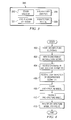
- FIG. 4 illustrates a flow chart describing an example method for the electronic design of collaborative and validated architectures in accordance with the present invention.
- FIGS. 1-4 of the drawings like numerals being used for like and corresponding parts of the various drawings.
- FIGS. 1-4 provide for a architecture design environment that utilizes consistent tools and consistent data to enable collaboration amongst designers and to improve the efficiency of electronic design.
- Architecture systems and components are maintained in a centralized repository making it possible for designers to draw from the same set of data and create designs that eliminate invalid and inconsistent components.
- Architectures may be stored both as component parts and as whole architectures. As a result, whole systems and component parts are available for use by designers.
- FIG. 1 illustrates a general purpose computer 100 that may be used for the electronic design of collaborative and validated architectures, in accordance with the present invention.
- general purpose computer 100 may comprise a computer that enables architects to collaboratively develop architectures, create reusable components, and reuse existing components.
- General purpose computer 100 may enforce architecture standards to ensure the correct use of only policy-approved architecture elements.
- General purpose computer 100 may provide validation against product lists maintained by a technology policy.
- General purpose computer 100 may enforce consistent labels, layouts, taxonomy, and definitions based on common architecture templates. Accordingly, in particular embodiments and as will be described in more detail below, general purpose computer 100 may enable designers to select from pre-defined platforms and design system architectures from a “catalog” without knowledge of the details of the underlying physical implementations and platforms.
- General purpose computer 100 may be adapted to execute any of the well known MS-DOS, PC-DOS, OS2, UNIX, MAC-OS and Windows operating systems or other operating systems.
- operating system may refer to the local operating system for computer 100 , a network operating system, or a combination of both.
- General purpose computer 100 comprises processor 112 , random access memory (RAM) 114 , read only memory (ROM) 116 , mouse 118 , keyboard 120 , and input/output devices such as printer 124 , disk drives 122 , display 126 , and communications link 128 .
- RAM random access memory
- ROM read only memory
- mouse 118 mouse 118
- keyboard 120 keyboard 120
- input/output devices such as printer 124 , disk drives 122 , display 126 , and communications link 128 .
- the present invention includes programs that may be stored in RAM 114 , ROM 116 , or disk drives 122 and may be executed by processor 112 .
- Disk drive 122 may include a variety of types of storage media such as, for example, floppy disk drives, hard disk drives, CD ROM drives, or magnetic tape drives. Disk drive 122 may also include a network disk housed in a server within the private network. Although this embodiment employs a plurality of disk drives 122 , a single disk drive 122 could be used without departing from the scope of the invention.
- FIG. 1 only provides one example of a computer that may be used with the invention.
- the invention could be used with computers other than general purpose computers as well as general purpose computers without conventional operating systems.
- FIG. 2 illustrates a block diagram of an example system 200 that may be used for the electronic design of collaborative and validated architectures in accordance with the present invention.
- client systems 202 are connected to an architecture creator system 204 via a network 206 .
- Architecture creator system 204 is used by client systems 202 to create architectures that include various combinations of architectural elements. Once created, the architectures and architectural elements are stored in a centralized repository 208 and may be used and reused by users of client systems 202 .
- clients 202 may be configured substantially like computer 100 described above with regard to FIG. 1 .
- clients 202 may include any general purpose computer with the appropriate applications and functionality for the electronic design of collaborative and validated architectures. Any number of client systems 202 may be included in system 200 .
- Network 206 represents communication equipment, including hardware and any appropriate controlling logic, for interconnecting client systems 202 and architecture creator system 204 .
- network 206 may comprise all or a portion of a radio access network; a public switched telephone network (PSTN); a public or private data network; a local area network (LAN); a metropolitan area network (MAN); a wide area network (WAN); a local, regional, or global communication or computer network such as the Internet; a wireline or wireless network; an enterprise intranet; or any combination of the preceding.
- PSTN public switched telephone network
- LAN local area network
- MAN metropolitan area network
- WAN wide area network
- communication network 206 may include routers, hubs, switches, gateways, call controllers, and/or any other suitable components in any suitable form or arrangement.
- communication network 206 is illustrated as a single network, communication network 206 may comprise any number or configuration of networks.
- Architecture creator system 204 which is described in more detail below with regard to FIG. 2 , includes the hardware and software required to create architectures that include various combinations of architectural elements. Reference architectures that are created may include business, process, logical, and physical views. Reference architectures that are used and/or created by architecture creator system 204 are stored in a centralized repository 208 . Centralized repository 208 makes it possible for users of clients 202 to draw from a common set of data and create designs that are consistent and reusable. Centralized repository 208 is a multi-user database that can support simultaneous data retrieval and storage for multiple users of architecture creator system 204 .
- centralized repository 208 includes a relational database or other data store that contains all or a portion of the reference data necessary to support the construction of architecture components.
- the architectures are stored in centralized repository 208 as wholes and as component elements such that both are available to designers for reuse.
- an architecture element may include any data element that can be input into the architecture creator system 204 .
- Architecture elements may be the lowest level of granularity in an architecture model.
- An architecture model is a grouping of architecture elements that relate to one another for a particular purpose or function.
- Centralized repository 208 stores both architecture elements and architecture models.
- an architecture stack may be created and stored in centralized repository 208 .
- An architecture stack is a pre-determined and approved grouping of architecture elements.
- the stack may include all views of an architecture, such as process views, logical views, and physical views, and may include elements from different views.
- An architecture stack is treated as a single reusable component. Each architecture element in a stack has an implicit dependence to at least one other architecture element in the stack.
- an architecture stack may include any combination of architecture elements, an architecture stack may also include embedded stacks.
- a single architecture stack may include multiple sub-grouping of pre-determined and approved architecture elements.
- centralized repository 208 may store both production stacks and draft stacks. While a production stack is a pre-determined and approved grouping of architecture elements, such as that described above, a draft stack includes a grouping of architecture elements that has not been approved or validated. Draft stacks may be appropriately identified as such to prevent reuse by users of clients 202 when only approved and validated architecture components and stacks may be used in a project.
- Centralized repository 208 may be populated with the architecture stacks and other reference data as such data is created or on a periodic basis. Once published to the centralized repository, an architecture stack is an actual reference architecture item that may serve as a future reference item. Architecture creator system 204 makes the data available for reuse by users of clients 202 .
- architecture creator system 204 creates a mirror copy of an accessed reference element and allows the user to place the mirror copy into an in-progress project.
- An identifier may be assigned to the minor copy to distinguish the mirror copy from the original reference component.
- architecture creator system 204 creates a relationship between the original, undisturbed reference data and the mirror copy used in the new project.
- Architecture creator system 204 may track how many times each reference data or architecture component is used in various projects.
- architecture creator system 200 includes a rules database 210 .
- Rules database 210 may include a relational database or other data store that contains all or a portion of the business and technical rules necessary to support the validation of architecture components. Business and technical rules may be established based on user-created architectures and/or technical specifications that identify the compatibility of various architecture elements with one another.
- the content of rules database 210 provides a framework or standard guide for the creation of validated architectures. For example, during the creation of an architecture model, a user of client 202 may be prevented from inserting two architecture elements into a model when those architecture elements are incompatible and/or violate a business rule in rules database 210 .
- geographic rules and placement diagrams may define where an architecture element should be deployed.
- rules database system 210 may include templates for each architecture type.
- system 200 has been described in detail, it should be understood that various changes, substitutions and alterations can be made to system 200 without departing from the sphere and scope of the invention.
- System 200 may have more or less components (of these or differing types) without departing from the scope of the invention.
- system 200 is illustrated as including both a centralized repository 208 and a rules database 210 , it is recognized that system 200 may include a single data store with the combined contents of centralized repository 208 and rules database 210 . Alternatively, the contents of these data stores may be divided among any appropriate number of data stores.
- FIG. 3 illustrates a block diagram of an example architecture creator system 300 .
- Architecture creator system 300 includes the hardware and software required to create architectures that include various combinations of architectural elements stored in a centralized repository, such as centralized repository 208 .
- architecture creator system 300 may be configured substantially like computer 100 described above with regard to FIG. 1 .
- architecture creator system 300 may include any general purpose computer with the appropriate applications and functionality for the creation, validation, retrieval, and analysis of architecture elements.
- an architecture stack includes a pre-determined and approved grouping of architecture elements.
- architecture creator system 300 includes a stack creator tool 302 .
- Stack creator tool 302 may include any hardware and software that allows for the creation of software, hardware, and process objects that can be grouped together to create a custom architecture component.
- Stack creator tool 302 enables users of clients 202 to build out logical groups of architecture components that are related to one another by a logical function.
- stack creator tool 302 may provide a graphical user interface that enables a user of client 202 to create a stack and save a stack to the repository.
- Existing stacks that stored in centralized repository may be modified so as to add or delete components.
- Stacks may be created or modified to include an embedded stack within a stack.
- the graphical user interface may prompt a user to give the stack a unique filename.
- the filename may be required to conform to a naming standard such as the Agile Enterprise Reference Architecture (AERA) standards guide.
- AERA Agile Enterprise Reference Architecture
- an existing stack may be renamed in compliance with any applicable naming standard.
- stack creator tool 302 allows the user to commit the stacks to centralized repository 208 .
- the number of stacks committed may be equal to the sum of the number of stacks and the number of architecture elements in each stack. This is because stack creator tool 302 commits architecture components to centralized repository 208 in their whole and individual forms.
- stack creation tool 302 may result in relationships being committed.
- stack creator tool 302 may also include functionality allowing a user to submit a stack for review and validation.
- a physical stack may depict the interface between structures, sub-assemblies, or assemblies and is used, specifically, to denote configurations for hardware or software.
- Software and hardware architectures may be created using stacks and then assigned to hardware to denote a specialized version of that hardware. Additionally, a single hardware item may have two stacks.
- a first stack for a hardware item may show the software required for the device.
- a second stack may indicate the hardware components such as disks, memory, or other components that identify the hardware item as a custom device.
- Example items that may be included in a physical stack include hardware items such as hardware model products, software items such as software version products, and embedded physical stacks.
- Hardware items and software items are sets of hardware devices and software products, respectively, that are used in the construction of infrastructure architectures.
- Hardware items include devices such as servers, routers, mainframes, switches, remote devices, and other hardware components.
- Software items may include operating systems, support software, databases, web servers, application servers, and other software components.
- the hardware items and software items may be loaded into centralized repository 208 based on a technology policy that may or may not be enterprise promulgated.
- Embedded physical stack items include a logical pre-defined grouping of hardware items and software items.
- Example items that may be included in a logical stack include logical application items, logical architecture items, embedded logical stacks, and role items.
- Logical application items include representations of a physical application but describe a business function.
- a logical application item is more generic than a physical application.
- logical architecture items include representations of functionality in a solution system that may translate into physical applications and software products.
- Logical role items describe the various user roles within an enterprise and denote the types of user that will utilize the resulting architecture.
- Embedded logical stack items include a logical pre-defined grouping of logical application items, logical architecture items, embedded logical stacks, and role items.
- Example items that may be included in a process stack include business function items, business process items, operational process items, and embedded process stacks.
- a business function item includes a core set of business functions defined at an enterprise level that are leveraged in the architecture to demonstrate how the sub-assemblies and assemblies support key business functions.
- a business process item includes a suite of business processes that support the business functions. Relationships established between business processes and business functions facilitate the use of business process and business function items.
- An operational process item includes a lower level operational process that supports the business processes.
- Embedded process stack items include a logical pre-defined grouping of business function items, business process items, operational process items.
- Architecture creator system 300 includes an architecture validator 304 that enables the review and approval of draft stacks.
- Architecture validator tool 304 may include any hardware and software that allows for the validation and approval of architecture items and stacks of architecture items.
- architecture validator tool 304 may provide a graphical user interface that identifies stacks and/or architecture items that have been recently added to centralized repository 208 or that have been submitted for validation by a creator. Using the graphical user interface, architecture validator tool 304 may identify stacks to be validated to a formal review committee. The review committee may review the stack to ensure the compatibility of architecture components with other architecture sub-assemblies. Upon approving or validating a stack, a user may use architecture validator tool 304 to change the status of a stack from “draft” to “production.”
- architecture creator tool 306 accesses rules database 210 to provide a user with a template for the creation of an architecture model or sub-assembly.
- Layers may be used to sub-divide a complete architecture into logical sub-groups. These sub-groups contain like components that service a particular function.
- the layering of architecture views of differing levels of abstraction allow architects to represent architecture from the highest level of abstraction down to the lowest level of detail.
- Example layers that may be included with in a template include: a physical hardware layer, a physical software layer, a logical applications layer, a logical components layer, an operational processes layer, a business processes layer, and a functional decomposition layer.
- Each layer will house the architecture components relating the particular subject of the layer.
- each layer may be stored in the repository as a whole and reused as a larger grouping within a model.
- an identifier Before any layers or architecture elements can be added to a model, an identifier must be assigned to the model.
- the identifier comprises an anchor for all architecture elements created in the model. Stated differently, all elements in the architecture model or sub-assembly may be connected to the identifier and will be identified by the identifier in centralized repository 208 for reuse.
- architecture creator tool 306 may provide a user with a list of architecture hierarchies at the highest level. A user can search for an existing architecture by the unique identifier assigned to that architecture.
- the layers associated with the model may be automatically imported from the repository and presented to the user.
- the architecture creator template offered by architecture creator tool 306 is limited to the scope of a single model.
- various layers of containers may be identified to the user.
- a user may select a particular layer or container and add an architecture element to the selected layer or container.
- a list of architecture elements that are available to the user may be presented.
- Architecture creator tool 306 may access rules database 210 and offer a list that include only the types of architecture elements that are eligible for use in the environment associated with the selected layer. For the modification of models that are in progress, a user may also be given the option of deleting a selected architecture element.
- architecture creator tool 306 may allow a user to add pre-defined stacks of architecture elements to a model. For example, a user may select a layer and then indicate that a pre-defined stack is to be added to the selected layer. A listing of stacks may be displayed to the user for selection. In particular embodiments, only the type of stacks that are eligible for use in the particular layer may be listed for a user. As a result, only the appropriate types of stacks may be selected by a user.
- architecture creator tool 306 allows a user to format the model.
- Architecture creator tool 306 may present various graphical user interface commands that allow a user to reposition, scale up, scale down, change the alignment, and resize architecture elements.
- Architecture creator tool 306 may also allow a user to select the size, style, and color of text. The color of an architecture element or a grouping of like architecture elements may be selected. Where predefined shapes are used for hardware elements, architecture creator tool 306 may allow a user to change the shape of such elements.
- Architecture creator tool 306 may also allow a user to create various links or relationships between architecture elements and between a model and various external specifications. For example, in a particular embodiment, a user may use architecture creator tool 306 may be used to link a document library to a model.
- a document library is an identifier of a data store that includes the documents that comprise an architecture.
- the identifier may include a uniform resource locator identifying the location of a web site library that is populated into centralized repository 208 .
- Architecture creator tool 306 may also be used to tie each element of an architecture to a release for which it is being developed. Connecting elements to the appropriate release allows users to easily identify which elements with the architecture creator system belong to which release. Elements that do not apply to a release may be grayed out. The features allows for the generation of a report to illustrate all architecture components that are associated with a particular release. It may be desirable at some point to disconnect an architecture element from a release. Accordingly, architecture creator tool 306 may provide additional functionality by which a user can disconnect one or more architecture elements from a user-specified release.
- architecture creator tool 306 may also allow a user to create a relationship between architecture elements in a model.
- the relationship between the architecture elements may include a primary relationship or a secondary relationship, and in some instances it may be desirable to create multiple relationships between two architecture elements.
- Example primary relationships include identifying that one architecture element needs another architecture element, that one architecture element has a corequisite, or that one architecture element has a prerequisite.
- a relationship between two architecture elements may be depicted in the final model as a line connecting the two.
- Architecture creator tool 306 may provide the user with formatting options for the relationships created between the architecture elements. Such formatting options may include line style, line color, line type, and line size. Where a particular data flow direction is desired, the user may select an indicator for identifying in the model the direction in which data should flow between the architecture elements. A traffic type may be selected where the traffic between two architecture elements is limited to a specific type of traffic. Still another formatting option may include they type of data flow protocol connecting the two elements, such as http, ftp, UDP, or another suitable protocol. In a particular embodiment, a user may specify a port number of the target architecture element to which data is transmitted. A user may also specify the type of information flowing between the architecture elements.
- a user may create a label that allows a data flow direction and purpose assigned to the relationship to be depicted on the resulting model.
- Architecture creator tool 306 may also allow a user to add comments to an architecture.
- a user may identify a particular layer or architecture element and create text that will be displayed in the architecture.
- architecture creator tool 306 may also allow a user to link a model with one or more business components, business rules, or technical requirement. Links to technical requirements may provide an explicit linkage between the requirements for the particular model and the model fulfilling those requirements.
- architecture creator tool 306 may present a user with a list of business or technical requirement linkage types, and the user may select the desired link. For example, a standardized list of available links may be provided to the user. In response to user selection of a desired link, architecture creator tool 306 may create an object link between the model and the selected link. Links to business rules and components show the value of the created model to the related business and may be useful in the generation of reports through an architecture reporter tool 308 that will be described in more detail below.
- architecture creator tool 306 may allow for the creation of integration stacks to provide a bridge between architecture components in different architecture models.
- An integration stack is a specialized stack that contains components that tie together large parts of other architectures. Integration stacks contain interface components that have key information to formulate technology rules and policies. Integration stacks may be used in solution based architectures to tie together different architectures and to describe the flow between the components of each assembly.
- Example items that may be allowed into an integration stack in a particular embodiment, may include enterprise-specific software applications, hardware products, software products, logical applications, logical architecture items, and embedded integration stacks.
- architecture creator tool 306 may create a public interface between two or more architectures.
- the public interface is distinguishable from a private interface that may refer to the interaction points between two components within a single architecture model.
- the public interface instead refers to the interaction points between two architecture models.
- the public interfaces allow user to define two-related architectures in the context of a “service” that can be consumed by other users.
- An integration stack may be created as an architecture is being built.
- an integration stack may be created by architecture creator tool 306 rather than by stack creator tool 302 .
- the process for creating an integration stack may be similar, however, to the process of creating a stack using stack creator tool 302 .
- architecture creator tool 306 may allow a user to identify where an integration stack will be placed and then insert the appropriate type of integration stack into the architecture.
- Architecture creator tool 306 may allow a user to name the integration stack, add descriptions about the stack, and add architecture elements to the stack.
- stack creator tool 302 described above, architecture creator tool 306 may limit a user's choices such that only architecture elements of the correct type may be provided as choices for the user to select when adding architecture elements to an integration stack.
- Each integration stack provides key components needed to communicate with the adjoining architecture component.
- the key to integrating the stack interfaces is the relationships between the adjoined integration stacks.
- the relationships carry a series of properties which contain information to link together the components.
- a special element may be used to bring in a representation of the external architecture and provide the connection into the key components of the integration stacks from that architecture.
- Architecture models created using architecture creator system 300 are meant to be used as components of larger architectures.
- Architecture creator tool 306 allows this to be done through architecture reuse. Specifically, architecture creator tool 306 assigns a URL field to each architecture element. Each URL field is populated with the location of the model file.
- different folders may be maintained and may describe the status or progress of a model. For example, a model may be saved in a work-in-progress folder while the model is under construction. Conversely, the model may be stored in a staging folder when the model is complete but is awaiting review. Models that are completed and have been reviewed and approved may be stored in a published folder that is available for production use.
- a user portal 308 provides the ability for the user to look at details of individual architecture components stored in centralized repository 208 that are used for reference in the design of new systems.
- User portal 308 includes a query system that enables a user to look view architecture elements organized by type. For example, a user can review a list of all components of that meet the requirements of the query.
- User portal 308 may enable a user to view a specific set of architecture elements and relationships stored in centralized repository 208 .
- a hierarchical tree structure may be used to display architecture elements. Various trees and sub-trees may be selected to refine a search for a particular architecture element.
- a search system may allow a user to submit text-based searches. In response to the text-based query, user portal 308 may present a subset of items with a similar name or string.
- User portal 308 includes a reporting system that provides standard and custom reports about the reference data stored in centralized repository 208 as well as stored architectures to determine areas as compliance and accuracy. A number of standard reports may be available. Additionally, portal 308 may includes features that allow a user to generate custom reports that support the individual needs of users of clients 202 . Reports generated by user portal 308 may include, in particular embodiments, column reports, bar charts, pie graphs, dial gauges, Gantt charts, and the like. Reports may be available in a variety of user-selectable formats. For example, in a particular embodiment, the user may select that a report be output in HTML format, PDF format, or Excel. Additionally or alternatively, reports may be exported into presentations, where desired.
- the components of architecture creator system 300 cooperate to enable multiple users to work on a single architecture in a collaborative environment. For example, when an architect has finished working on a portion of the architecture, the architect commits the architecture to the repository. Once committed, the architecture is available to other architects. Such an architect may retrieve the portion of the architecture from the repository and continue working on the portion. To prevent changes to a previous user's work, subsequent users may create working copies of the architecture and make changes to that copy. Additionally or alternatively, a user may retrieve an architecture and save it in an empty template before making modifications. When the user is finished, the architect again commits the portion to the repository.
- architecture creator system 300 may provide a check-in/check-out system that requires a user to check out an architecture before the user can work on it. Once checked out, the architecture is unavailable to other architects until it is checked back in.
- FIG. 4 illustrates a flow chart describing an example method for the electronic design of collaborative and validated architectures in accordance with the present invention.
- the method described herein may be carried out using computer software, as can any or all of the processes described herein. That software may be executed by computer 10 , architecture creator system 204 , or any other computer or combination of computers.
- the method initiates at step 400 , where a plurality of architecture elements created by a plurality of users are stored in a centralized database 208 .
- Some of the architecture elements may include logical groupings of architecture elements that are related to one another by a logical function. These related architecture elements may be stored in centralized database as an integrated architecture stack, in a particular embodiment.
- Each architecture element in an architecture stack may have a dependence upon or relationship with at least one other architecture element in the same architecture stack.
- an architecture stack may include an embedded architecture stack that is comprised of a logical sub-grouping of architecture elements.
- the creation of a first architecture model is initiated in response to a request of a first user of a first client system 202 .
- initiating the creation of the first architecture model may include presenting a template to the user.
- a plurality of layers or other containers may be presented to the user.
- Each layer or container may be configured to include a logical sub-group of architecture elements selected by the user.
- a selection by a user of a particular layer may be received, and a listing of architecture elements that are suitable for inclusion in the layer may be presented to the user.
- centralized database 208 is accessed to retrieve architecture elements for inclusion in the architecture model.
- the architecture elements or a subset thereof may be presented to a user for inclusion in the architecture model.
- the a filter may be applied to the architecture elements in centralized database 208 .
- the architecture elements may be filtered based on a type of the first architecture model. Where a filter is applied, only the architecture elements that are suitable for the particular architecture model may be presented.
- a selection of at least one architecture element may be received from a user.
- the selection may identify individual architecture elements for inclusion in the architecture model. Additionally or alternatively, the selection may include the selection of an architecture stack. In a particular embodiment, the selection may include the selection of a grouping of architecture elements.
- the architecture model and the architecture elements making up the architecture model may be stored in the centralized database.
- the architecture elements that make up the architecture model may be stored individually.
- the grouping may be stored as an architecture stack.
- the status of the architecture model may indicate it as a draft model.
- the architecture model created by the user may be validated.
- an architecture creator system 204 may automatically determine if the first architecture model and the architecture elements making up the architecture model are compliant with one or more technical or business rules.
- the architecture model may be validated if the architecture model and its component parts are compliant with the one or more technical or business rules. Additionally or alternatively, the architecture model may be accessed by a review committee who may determine if the architecture model and its component parts are compliant with the one or more technical or business rules.
- the status of the architecture model as stored in the centralized database may be changed from “draft” to “production.”
- the architecture model as stored in centralized database 208 may be available for reuse by other users of architecture creator system 204 .
- a subsequent user of architecture creator system 204 may access the stored architecture model. The subsequent user may then modify the architecture model where a collaboration is desired among multiple architects. Alternatively, the subsequent user may copy the architecture model and begin altering the architecture model for the creation of an entirely new architecture model.
- a mirror copy of the architecture model may be created. The subsequent user may then modify the mirror copy of the architecture model such that the original copy of the architecture model remains unchanged.
- an additional step that may be performed may include linking the architecture model or one or more elements within the architecture model with one or more stored business rules or technical requirements. Additionally or alternatively, the architecture model or its one or more architecture elements may be linked with a second architecture model. Finally, additional steps may be performed for the generation of custom or standard reports. Such reports may include information about the architecture elements in the first architecture model and one or more business or technical rules applicable to the first architecture model.
- FIGS. 1, 2, and 3 merely represent example configurations for the components of systems 100 , 200 , and 300 , respectively. It is recognized that many modifications to these systems may be made without departing from the intended scope of the invention.
Landscapes
- Engineering & Computer Science (AREA)
- Computer Hardware Design (AREA)
- Physics & Mathematics (AREA)
- Theoretical Computer Science (AREA)
- Evolutionary Computation (AREA)
- Geometry (AREA)
- General Engineering & Computer Science (AREA)
- General Physics & Mathematics (AREA)
- Stored Programmes (AREA)
Abstract
Description
Claims (36)
Priority Applications (1)
| Application Number | Priority Date | Filing Date | Title |
|---|---|---|---|
| US12/122,425 US9317640B2 (en) | 2008-05-16 | 2008-05-16 | System and method for the electronic design of collaborative and validated architectures |
Applications Claiming Priority (1)
| Application Number | Priority Date | Filing Date | Title |
|---|---|---|---|
| US12/122,425 US9317640B2 (en) | 2008-05-16 | 2008-05-16 | System and method for the electronic design of collaborative and validated architectures |
Publications (2)
| Publication Number | Publication Date |
|---|---|
| US20090287635A1 US20090287635A1 (en) | 2009-11-19 |
| US9317640B2 true US9317640B2 (en) | 2016-04-19 |
Family
ID=41317086
Family Applications (1)
| Application Number | Title | Priority Date | Filing Date |
|---|---|---|---|
| US12/122,425 Expired - Fee Related US9317640B2 (en) | 2008-05-16 | 2008-05-16 | System and method for the electronic design of collaborative and validated architectures |
Country Status (1)
| Country | Link |
|---|---|
| US (1) | US9317640B2 (en) |
Cited By (2)
| Publication number | Priority date | Publication date | Assignee | Title |
|---|---|---|---|---|
| US20150213407A1 (en) * | 2014-01-30 | 2015-07-30 | Mentor Graphics Corporation | Social electronic design automation |
| US20150347656A1 (en) * | 2014-05-27 | 2015-12-03 | Mentor Graphics Corporation | System design management |
Families Citing this family (2)
| Publication number | Priority date | Publication date | Assignee | Title |
|---|---|---|---|---|
| CN104272294B (en) * | 2012-07-31 | 2017-03-29 | 慧与发展有限责任合伙企业 | Generate the method and system of particular system framework |
| US10002120B2 (en) * | 2015-04-30 | 2018-06-19 | Sap Se | Computer implemented systems and methods for data usage monitoring |
Citations (6)
| Publication number | Priority date | Publication date | Assignee | Title |
|---|---|---|---|---|
| US5767848A (en) * | 1994-12-13 | 1998-06-16 | Hitachi, Ltd. | Development support system |
| US5826265A (en) * | 1996-12-06 | 1998-10-20 | International Business Machines Corporation | Data management system having shared libraries |
| US6917909B1 (en) | 1998-05-18 | 2005-07-12 | Lev A. Markov | Facilitating guidance provision for an architectural exploration based design creation process |
| US7076417B2 (en) | 2001-09-05 | 2006-07-11 | Agilent Technologies, Inc. | Method for modeling and processing asynchronous functional specification for system level architecture synthesis |
| US20070260436A1 (en) * | 2006-04-27 | 2007-11-08 | Lockheed Martin Integrated Systems And Solutions | System and method for evaluating system architectures |
| US7546571B2 (en) * | 2004-09-08 | 2009-06-09 | Mentor Graphics Corporation | Distributed electronic design automation environment |
-
2008
- 2008-05-16 US US12/122,425 patent/US9317640B2/en not_active Expired - Fee Related
Patent Citations (6)
| Publication number | Priority date | Publication date | Assignee | Title |
|---|---|---|---|---|
| US5767848A (en) * | 1994-12-13 | 1998-06-16 | Hitachi, Ltd. | Development support system |
| US5826265A (en) * | 1996-12-06 | 1998-10-20 | International Business Machines Corporation | Data management system having shared libraries |
| US6917909B1 (en) | 1998-05-18 | 2005-07-12 | Lev A. Markov | Facilitating guidance provision for an architectural exploration based design creation process |
| US7076417B2 (en) | 2001-09-05 | 2006-07-11 | Agilent Technologies, Inc. | Method for modeling and processing asynchronous functional specification for system level architecture synthesis |
| US7546571B2 (en) * | 2004-09-08 | 2009-06-09 | Mentor Graphics Corporation | Distributed electronic design automation environment |
| US20070260436A1 (en) * | 2006-04-27 | 2007-11-08 | Lockheed Martin Integrated Systems And Solutions | System and method for evaluating system architectures |
Non-Patent Citations (2)
| Title |
|---|
| Troux technologies, "Troux Transformation Platform(TM) Unlocks the Full Power of Enterprise Architecture," 2 pages. |
| Troux technologies, "Troux Transformation Platform™ Unlocks the Full Power of Enterprise Architecture," 2 pages. |
Cited By (4)
| Publication number | Priority date | Publication date | Assignee | Title |
|---|---|---|---|---|
| US20150213407A1 (en) * | 2014-01-30 | 2015-07-30 | Mentor Graphics Corporation | Social electronic design automation |
| US10445699B2 (en) * | 2014-01-30 | 2019-10-15 | Mentor Graphics Corporation | Social electronic design automation |
| US20150347656A1 (en) * | 2014-05-27 | 2015-12-03 | Mentor Graphics Corporation | System design management |
| US9734273B2 (en) * | 2014-05-27 | 2017-08-15 | Mentor Graphics Corporation | System design management |
Also Published As
| Publication number | Publication date |
|---|---|
| US20090287635A1 (en) | 2009-11-19 |
Similar Documents
| Publication | Publication Date | Title |
|---|---|---|
| Lee et al. | Rules and validation processes for interoperable BIM data exchange | |
| US7266549B2 (en) | Optimization using a multi-dimensional data model | |
| US7673282B2 (en) | Enterprise information unification | |
| US7685140B2 (en) | Dynamic information systems | |
| US7600182B2 (en) | Electronic data capture and verification | |
| CN101297268B (en) | Integrated systems, tools and methods for designing automated business process applications | |
| AU2002346038B2 (en) | Managing reusable software assets | |
| US8176002B2 (en) | Method and system for user alteration of the configuration of a data warehouse | |
| AU2013205927B2 (en) | Methodology infrastructure and delivery vehicle | |
| US20130013993A1 (en) | Spreadsheet-based templates for supporting the systems engineering process | |
| US20040093559A1 (en) | Web client for viewing and interrogating enterprise data semantically | |
| US20080195651A1 (en) | Batch Management of Metadata in a Business Intelligence Architecture | |
| MXPA06010977A (en) | A forms development platform. | |
| CN102222278A (en) | Operation process customizing method and device | |
| US8090677B2 (en) | Method and system for altering the configuration of a data warehouse | |
| Lee et al. | Product data modeling using GTPPM—A case study | |
| US9317640B2 (en) | System and method for the electronic design of collaborative and validated architectures | |
| US20070033212A1 (en) | Semantic model development and deployment | |
| Janner et al. | A core component-based modelling approach for achieving e-business semantics interoperability | |
| Eriksson et al. | The pluss toolkit? extending telelogic doors and ibm-rational rose to support product line use case modeling | |
| Jennings | Microsoft Access 2010 in depth | |
| MacDonald | Managing Workflow with XML Web Services | |
| Saaksvuori et al. | Product lifecycle management systems | |
| Lampathaki et al. | A Core Component-based Modelling Approach for Achieving e-Business Semantics Interoperability | |
| Qian | Financial aid data warehouse (Master of Software Engineering) |
Legal Events
| Date | Code | Title | Description |
|---|---|---|---|
| AS | Assignment |
Owner name: ELECTRONIC DATA SYSTEMS CORPORATION, TEXAS Free format text: ASSIGNMENT OF ASSIGNORS INTEREST;ASSIGNORS:BELVILLE, DANIEL R.;CARTER, MICHAEL K.;PETROWSKI, ROBIN R.;REEL/FRAME:020961/0179 Effective date: 20080515 |
|
| AS | Assignment |
Owner name: ELECTRONIC DATA SYSTEMS, LLC, DELAWARE Free format text: CHANGE OF NAME;ASSIGNOR:ELECTRONIC DATA SYSTEMS CORPORATION;REEL/FRAME:022460/0948 Effective date: 20080829 Owner name: ELECTRONIC DATA SYSTEMS, LLC,DELAWARE Free format text: CHANGE OF NAME;ASSIGNOR:ELECTRONIC DATA SYSTEMS CORPORATION;REEL/FRAME:022460/0948 Effective date: 20080829 |
|
| AS | Assignment |
Owner name: HEWLETT-PACKARD DEVELOPMENT COMPANY, L.P., TEXAS Free format text: ASSIGNMENT OF ASSIGNORS INTEREST;ASSIGNOR:ELECTRONIC DATA SYSTEMS, LLC;REEL/FRAME:022449/0267 Effective date: 20090319 Owner name: HEWLETT-PACKARD DEVELOPMENT COMPANY, L.P.,TEXAS Free format text: ASSIGNMENT OF ASSIGNORS INTEREST;ASSIGNOR:ELECTRONIC DATA SYSTEMS, LLC;REEL/FRAME:022449/0267 Effective date: 20090319 |
|
| AS | Assignment |
Owner name: HEWLETT PACKARD ENTERPRISE DEVELOPMENT LP, TEXAS Free format text: ASSIGNMENT OF ASSIGNORS INTEREST;ASSIGNOR:HEWLETT-PACKARD DEVELOPMENT COMPANY, L.P.;REEL/FRAME:037079/0001 Effective date: 20151027 |
|
| STCF | Information on status: patent grant |
Free format text: PATENTED CASE |
|
| AS | Assignment |
Owner name: ENTIT SOFTWARE LLC, CALIFORNIA Free format text: ASSIGNMENT OF ASSIGNORS INTEREST;ASSIGNOR:HEWLETT PACKARD ENTERPRISE DEVELOPMENT LP;REEL/FRAME:042746/0130 Effective date: 20170405 |
|
| AS | Assignment |
Owner name: JPMORGAN CHASE BANK, N.A., DELAWARE Free format text: SECURITY INTEREST;ASSIGNORS:ATTACHMATE CORPORATION;BORLAND SOFTWARE CORPORATION;NETIQ CORPORATION;AND OTHERS;REEL/FRAME:044183/0718 Effective date: 20170901 Owner name: JPMORGAN CHASE BANK, N.A., DELAWARE Free format text: SECURITY INTEREST;ASSIGNORS:ENTIT SOFTWARE LLC;ARCSIGHT, LLC;REEL/FRAME:044183/0577 Effective date: 20170901 |
|
| CC | Certificate of correction | ||
| AS | Assignment |
Owner name: MICRO FOCUS LLC, CALIFORNIA Free format text: CHANGE OF NAME;ASSIGNOR:ENTIT SOFTWARE LLC;REEL/FRAME:050004/0001 Effective date: 20190523 |
|
| MAFP | Maintenance fee payment |
Free format text: PAYMENT OF MAINTENANCE FEE, 4TH YEAR, LARGE ENTITY (ORIGINAL EVENT CODE: M1551); ENTITY STATUS OF PATENT OWNER: LARGE ENTITY Year of fee payment: 4 |
|
| AS | Assignment |
Owner name: MICRO FOCUS LLC (F/K/A ENTIT SOFTWARE LLC), CALIFORNIA Free format text: RELEASE OF SECURITY INTEREST REEL/FRAME 044183/0577;ASSIGNOR:JPMORGAN CHASE BANK, N.A.;REEL/FRAME:063560/0001 Effective date: 20230131 Owner name: NETIQ CORPORATION, WASHINGTON Free format text: RELEASE OF SECURITY INTEREST REEL/FRAME 044183/0718;ASSIGNOR:JPMORGAN CHASE BANK, N.A.;REEL/FRAME:062746/0399 Effective date: 20230131 Owner name: MICRO FOCUS SOFTWARE INC. (F/K/A NOVELL, INC.), WASHINGTON Free format text: RELEASE OF SECURITY INTEREST REEL/FRAME 044183/0718;ASSIGNOR:JPMORGAN CHASE BANK, N.A.;REEL/FRAME:062746/0399 Effective date: 20230131 Owner name: ATTACHMATE CORPORATION, WASHINGTON Free format text: RELEASE OF SECURITY INTEREST REEL/FRAME 044183/0718;ASSIGNOR:JPMORGAN CHASE BANK, N.A.;REEL/FRAME:062746/0399 Effective date: 20230131 Owner name: SERENA SOFTWARE, INC, CALIFORNIA Free format text: RELEASE OF SECURITY INTEREST REEL/FRAME 044183/0718;ASSIGNOR:JPMORGAN CHASE BANK, N.A.;REEL/FRAME:062746/0399 Effective date: 20230131 Owner name: MICRO FOCUS (US), INC., MARYLAND Free format text: RELEASE OF SECURITY INTEREST REEL/FRAME 044183/0718;ASSIGNOR:JPMORGAN CHASE BANK, N.A.;REEL/FRAME:062746/0399 Effective date: 20230131 Owner name: BORLAND SOFTWARE CORPORATION, MARYLAND Free format text: RELEASE OF SECURITY INTEREST REEL/FRAME 044183/0718;ASSIGNOR:JPMORGAN CHASE BANK, N.A.;REEL/FRAME:062746/0399 Effective date: 20230131 Owner name: MICRO FOCUS LLC (F/K/A ENTIT SOFTWARE LLC), CALIFORNIA Free format text: RELEASE OF SECURITY INTEREST REEL/FRAME 044183/0718;ASSIGNOR:JPMORGAN CHASE BANK, N.A.;REEL/FRAME:062746/0399 Effective date: 20230131 |
|
| FEPP | Fee payment procedure |
Free format text: MAINTENANCE FEE REMINDER MAILED (ORIGINAL EVENT CODE: REM.); ENTITY STATUS OF PATENT OWNER: LARGE ENTITY |
|
| LAPS | Lapse for failure to pay maintenance fees |
Free format text: PATENT EXPIRED FOR FAILURE TO PAY MAINTENANCE FEES (ORIGINAL EVENT CODE: EXP.); ENTITY STATUS OF PATENT OWNER: LARGE ENTITY |
|
| STCH | Information on status: patent discontinuation |
Free format text: PATENT EXPIRED DUE TO NONPAYMENT OF MAINTENANCE FEES UNDER 37 CFR 1.362 |
|
| STCH | Information on status: patent discontinuation |
Free format text: PATENT EXPIRED DUE TO NONPAYMENT OF MAINTENANCE FEES UNDER 37 CFR 1.362 |
|
| FP | Lapsed due to failure to pay maintenance fee |
Effective date: 20240419 |