US9317477B1 - Method for transferring 16-bit data through 8-bit devices - Google Patents
Method for transferring 16-bit data through 8-bit devices Download PDFInfo
- Publication number
- US9317477B1 US9317477B1 US13/445,248 US201213445248A US9317477B1 US 9317477 B1 US9317477 B1 US 9317477B1 US 201213445248 A US201213445248 A US 201213445248A US 9317477 B1 US9317477 B1 US 9317477B1
- Authority
- US
- United States
- Prior art keywords
- bit
- fuze
- controller
- encoder
- bit data
- Prior art date
- Legal status (The legal status is an assumption and is not a legal conclusion. Google has not performed a legal analysis and makes no representation as to the accuracy of the status listed.)
- Expired - Fee Related, expires
Links
Images


Classifications
-
- H—ELECTRICITY
- H03—ELECTRONIC CIRCUITRY
- H03M—CODING; DECODING; CODE CONVERSION IN GENERAL
- H03M7/00—Conversion of a code where information is represented by a given sequence or number of digits to a code where the same, similar or subset of information is represented by a different sequence or number of digits
- H03M7/14—Conversion to or from non-weighted codes
- H03M7/24—Conversion to or from floating-point codes
-
- G—PHYSICS
- G06—COMPUTING OR CALCULATING; COUNTING
- G06F—ELECTRIC DIGITAL DATA PROCESSING
- G06F17/00—Digital computing or data processing equipment or methods, specially adapted for specific functions
- G06F17/10—Complex mathematical operations
-
- F—MECHANICAL ENGINEERING; LIGHTING; HEATING; WEAPONS; BLASTING
- F42—AMMUNITION; BLASTING
- F42C—AMMUNITION FUZES; ARMING OR SAFETY MEANS THEREFOR
- F42C17/00—Fuze-setting apparatus
- F42C17/04—Fuze-setting apparatus for electric fuzes
Definitions
- the present invention relates in general to the field of munitions. More specifically, this invention relates to a method and associated computer program product for encoding and transmitting a digital 16-bit data stream through 8-bit modules.
- the present invention may be used, for example in a new velocity correction circuitry in a fuze, to provide adjustment of detonation times issued from fire control.
- Serial communication is one of the functions often required in the development of integrated microsystems.
- a serial interface unit sends and receives bit sequences on the status of these bits, to and from another unit that processes the bit sequence.
- serial input/output (SIO) unit is a serial interface used for communicating with other units. It is also important for low power consumption in portable applications.
- the amount of serial data is fixed in the conventional SIO.
- the width of the data is fixed at 8 bits or 16 bits.
- An operator selects either the 8-bit or the 16-bit serial interface depending on the design.
- such manual selection between the 8-bit and the 16-bit may hamper the use of new technological advancements in connection with existing or “vintage” devices.
- ordnance systems such as artillery shells, rocket propelled munitions, mortar shells and the like, are becoming increasingly, technologically sophisticated, with communication and accuracy playing a fundamental role.
- the main problem with communications lies in transferring a 16-bit data stream by using a 16-bit platform in ordnance systems that are either incapable, or that do not adequately support the 16-bit platform.
- Conventional methods have been proposed to address this concern.
- One such conventional method proposes updating the electronic circuitry to a platform that can handle the size of the data being transferred. In this case, it would be the expansion of an 8-bit processor to a 16-bit processor. However, the complexity of such expansion significantly increases the cost, space constraint, complexity, and power consumption of the system.
- the present invention satisfies this need, and describes a new method and associated computer program product (collectively referred to herein as “the invention,” “the present invention,” “the computer program product,” or “the product” for encoding and transmitting 16-bit data through 8-bit modules, without hardware modifications to the ordnance systems.
- the present invention may be used for example, in a new velocity correction circuitry of a fuze controller, to provide adjustment of detonation times issued from fire control.
- a specific number is to be transferred between two modules, such as for example, only, a velocity correction module and a fuze controller.
- the velocity correction module computes the actual exit velocity of the projectile and stores this figure in the form of a number that is to be transferred and loaded into the fuze controller.
- This uploaded data is to provide the fuze with a live exit velocity so the fuze can more accurately predict an airburst time delay. It is therefore critical that once a number is determined in the velocity correction module, there is no loss of precision, and that the data is transferred as fast as possible to minimize any error. Once the data is transferred from module to module, the fuze is able to update the time delay accordingly and detonate at the correct time.
- the velocity correction circuitry requires a 16-bit architecture to perform complex calculations based on sensor data.
- the present invention corrects the detonation time from a ballistic table, based on the actual velocity of a projectile measured upon exit of the projectile from the gun tube or muzzle.
- the present invention provides precise timing adjustment to the currently existing fuze built upon an 8-bit architecture. It significantly improves the accuracy of detonation times for air burst mode.
- the present computer program product solves the problem of transferring the 16-bit data stream between modules, by reducing or encoding the 16-bit data stream into a two-part, 8-bit data stream.
- the computer program product may optionally expand or decode the two-part, 8-bit data stream back into the original 16-bit data stream without significant loss of precision or error into the computation.
- the present invention becomes of particular importance when transferring large data sizes on a reduced processor platform.
- the present invention includes an encoder or encoding module that converts the inputted 16-bit data stream, T, into a two-part 8-bit data stream, X and Y.
- the encoder calculates the truncate square root, X, of the input number, e.g., time delay, T, and transmits the calculated square root as an 8-bit data stream.
- the encoder further calculates an error correction number, Y, and transmits it as an 8-bit data stream.
- the error correction number, Y is calculated by subtracting the square number X from the original number, T.
- the original time delay number, T can now be viewed as a composite of two 8 bit numbers, X and Y.
- the two 8-bit numbers, X and Y are then transferred to a fuze, and optionally (though not necessarily) expanded or decoded, to provide the actual time delay, T.
- FIG. 1 is a schematic illustration of an ordnance system incorporating the computer program product of the present invention, and showing a projectile housed with a gun, prior to firing;
- FIG. 2 is a schematic illustration of the ordnance system of FIG. 1 , showing the projectile exiting a barrel of the gun, after firing;
- FIG. 3 is a schematic illustration of the projectile shown approaching a designated target
- FIG. 4 is an exploded view of the projectile of FIGS. 1, 2, and 3 , illustrating the location of the present computer program product within the projectile;
- FIG. 5 is a high level block diagram of the components of the computer program product, according to a preferred embodiment of the present invention.
- FIG. 6 is a flow chart illustrating the operation of the computer program product of FIG. 5 ;
- FIG. 7 is a high level block diagram of the components of the computer program product according to an alternative embodiment of the present invention.
- FIG. 8 is a flow chart illustrating the operation of the computer program product of FIG. 7 .
- FIG. 5 it illustrates a preferred embodiment of a computer program product 100 according to a preferred embodiment of the present invention.
- the computer program product 100 is embedded within, or programmed onto a 16-bit to 8-bit encoder (or encoding module) 500 that receives an input 16-bit data stream containing a number, T, from a sensor (or sensors) 505 , for transmission to an 8-bit platform, such as a fuze controller 510 .
- the fuze controller 510 reconstructs the original 16-bit input data stream as an 8-bit representation of the 16-bit number, T, with minimal errors.
- FIG. 4 shows an exemplary projectile 400 as including a forward section 410 , an aft section 420 , and a body 430 .
- the sensor 505 is preferably located at, or within the forward section 410 . Such disposition of the sensor 505 will ensure an expedient and accurate reading of the sensed parameter, as soon as the projectile 400 exits a barrel 200 of a gun (or ordnance) system 250 ( FIGS. 1 and 2 ).
- the fuze and the computer program product 100 are disposed within the body 430 .
- the fuze controller 510 is fed (or programmed) with an approximate timing value, T e , that is based on an estimated exit velocity of the projectile 400 from the gun barrel 200 , the proximity of the gun system 250 from the intended target 300 ( FIG. 3 ), and other parameters that affect the flight path of the projectile 200 .
- the fuze controller 510 will be initiated (i.e., detonate) at the expiration of the approximate timing value, T e .
- the sensor 505 measures, for example, the actual exit velocity of the projectile forward section 410 .
- the encoder 500 calculates a new accurate timing value, T, and transmits this accurate value, T, to the fuze controller 510 .
- T a 16-bit accurate timing value
- the fuze controller 510 is an 8-bit unit that is incapable of directly processing the 16-bit accurate timing value, T.
- the encoder 500 divides the 16-bit accurate timing value, T, into a two-part 8-bit data stream, X and Y, as it will be described later in greater detail by the examples to follow.
- the encoder 500 transmits the 8-bit data stream (X, Y) to the fuze controller 510 .
- the fuze controller 510 uses the 8-bit values (X, Y) to reconstruct the accurate timing value, T, as an 8-bit data stream, and to use this accurate timing value, T, for detonation, thus achieving a very highly accurate adjustment of the detonation time.
- the number, T, to be transmitted represents an accurate fuzing time that has been provided by (or processed from a reading secured by) the sensor 505 .
- the sensor 505 is a velocity correction module (also referenced herein as 505 ).
- the velocity correction module (or sensor) 505 computes the actual exit velocity of the projectile 400 , and stores this figure in the form of a number, T, that is to be transferred and loaded into the fuze controller 510 .
- T The purpose of this input number, T, is to provide the fuze controller 510 capability to accurately predict an airburst time delay using a live exit velocity.
- T the number of milliseconds in the velocity correction module 505 . It is therefore critical that once the number, T, is determined in the velocity correction module 505 , there is no loss of precision, and that the data is transferred as fast as possible (e.g., within a few milliseconds to approximately 25 milliseconds) to minimize any error. Once the data, T, is transferred to the fuze controller 510 , the fuze controller 510 will update the time delay accordingly, to cause detonation at the accurate time.
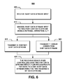
- FIG. 6 is a flow chart that illustrates a process of operation 600 of the computer program product 100 of FIG. 5 .
- the velocity correction module 505 can, for example, compute numbers up to 65,536 (16 bits).
- the fuze controller 510 would require a larger processor than the existing 8-bit processor of the fuze controller 510 .
- the velocity correction module 505 senses or computes the 16-bit time delay number, T, and transfers it to the computer program product 100 .
- the encoder module 500 receives the 16-bit time delay number, T, from the sensor module 505 .
- the encoder module 500 divides, at step 610 , the time delay number, T, into a two-part 8-bit data stream that includes an integer (whole number), X, and an error value, Y.
- the encoder module 500 transmits the two values X and Y to the fuze controller 510 .
- the fuze controller 510 can either use the two 8-bit data (X, Y) decodes the two received numbers, X, Y; or it can alternatively reconstruct the original time delay number T as a single 16-bit data stream using the received numbers X, Y.
- the encoder 500 calculates the truncated, square rooted, X, of the input time delay number, as well as the error correction number, Y. The encoder 500 then transmits both numbers X and Y as an 8-bit data stream to the fuze controller 510 .
- the algorithm used by the encoder 500 to encode the input 16-bit data stream into a two-part 8-bit data stream ensures fast and reliable data transfer and timing accuracy that is preserved across two different architectures. This helps to limit the redesign of the fuze circuitry while enhancing its capability, by placing the design burden on a module or system outside of the fuze controller 510 .
- FIG. 7 illustrates an alternative computer program product 700 of the present invention, using the same numeral references as the computer program product 100 of FIG. 5 , in order to clarify that the computer program product 700 may use the same or similar components as the computer program product 100 .
- the computer program product 700 is embedded within, or programmed onto a 16-bit to 8-bit encoder (or encoding module) 500 that receives an input 16-bit data stream from one or more sensors 505 , for transmission to a fuze controller 710 .
- the fuze controller 710 may either be an 8-bit platform or a 16-bit platform. If the fuze controller 710 were a 16-bit platform, the computer program product 700 will be provided with an 8-bit to a 16-bit decoder (or decoding module) 720 , which reconstructs the original input 16-bit data stream [X, Y], with minimal errors.
- the 16-bit fuze controller 710 instructs the encoder 500 to bypass the decoder 720 entirely and to directly transmit the 16-bit data stream to the fuze controller 710 , as shown by the arrow 777 .
- the encoder 500 transmits the two 8-bit data stream to the fuze controller 710 , as described earlier, as shown by the arrow 777 .
- FIG. 8 is a flow chart that illustrates a process of operation 800 of the computer program product 700 of FIG. 7 .
- the velocity correction module 505 can, for example, compute numbers up to 65,536 (16 bits).
- the velocity correction module 505 senses or computes the 16-bit time delay number, T, and transfers it to the computer program product 700 .
- the encoder module 500 receives the 16-bit time delay number, T, from the sensor module 505 .
- the process 800 determines whether the fuze controller 710 is an 8-bit or a 16-bit platform. If it is determined that the fuze controller 710 is a 16-bit platform, then process 800 makes another determination, at step 815 as to whether it is desired to bypass the decoder 720 . If so, then the encoder 500 does not encode the 16-bit input data stream, but rather transmits it directly to the fuze controller 710 , along the arrow 777 , at step 820 .
- the encoder module 500 divides, at step 825 , the time delay number, T, into a two-part 8-bit data stream that includes an integer (whole number), X, and an error value, Y.
- the encoder module 500 transmits the two values X and Y to an optional 8-bit to 16-bit decoder 720 .
- the decoder 720 transmits the reconstructed 16-bit data stream, T, to the fuze controller 710 .
- process 800 uses process 600 , as described earlier in connection with FIG. 6 .
Landscapes
- Engineering & Computer Science (AREA)
- Theoretical Computer Science (AREA)
- General Engineering & Computer Science (AREA)
- Physics & Mathematics (AREA)
- Mathematical Physics (AREA)
- Data Mining & Analysis (AREA)
- General Physics & Mathematics (AREA)
- Mathematical Analysis (AREA)
- Mathematical Optimization (AREA)
- Pure & Applied Mathematics (AREA)
- Databases & Information Systems (AREA)
- Software Systems (AREA)
- Computational Mathematics (AREA)
- Algebra (AREA)
- Radar Systems Or Details Thereof (AREA)
Abstract
Description
Time Delay (T)=X 2 +Y (1)
X=T 1/2 (Truncate Value) (2)
Y=T−X 2 (Square root Error Value) (3)
-
- a) Find X:
- 1. Take the square root of T: √(T)=√(13739)=117.2134
- 2. Truncate (or round) the above square rooted number to obtain an integer, X:
- X=Floor [√(T)]=Floor [117.2134]=117
- b) Find Y:
- 3. Square X: X2=(Floor [√(T)])2=(117)2=13689
- 4. Find Y: Y=T−X2=13739−13689=50
- c) Transmit the two 8-bit numbers X and Y (optionally along with a checksum):
- X=117=(Hex 75)
- Y=50=(Hex 32)
- CHECK: T=X2+Y=(117)2+50=13739
- a) Find X:
-
- a) Find X:
- 1. Take the Square Root: √(T)=√(8275)=90.9670
- 2. Truncate (or round) the above square rooted number to obtain an integer, X:
- X=Floor [√(T)]=Floor [90.9670]=90
- b) Find Y:
- 3. Square X: X2=(Floor [√(T)])2=(90)2=8100
- 4. Y=T−X2=8275−8100=175
- c) Transmit the two 8-bit numbers X and Y (optionally along with a checksum):
- X=90=(Hex 5A)
- Y=175=(Hex AF)
- CHECK: T=X2+Y=(90)2+175=8275
- a) Find X:
Time Delay (T)=X 2 +Y.
Claims (1)
Priority Applications (1)
| Application Number | Priority Date | Filing Date | Title |
|---|---|---|---|
| US13/445,248 US9317477B1 (en) | 2012-04-12 | 2012-04-12 | Method for transferring 16-bit data through 8-bit devices |
Applications Claiming Priority (1)
| Application Number | Priority Date | Filing Date | Title |
|---|---|---|---|
| US13/445,248 US9317477B1 (en) | 2012-04-12 | 2012-04-12 | Method for transferring 16-bit data through 8-bit devices |
Publications (1)
| Publication Number | Publication Date |
|---|---|
| US9317477B1 true US9317477B1 (en) | 2016-04-19 |
Family
ID=55700029
Family Applications (1)
| Application Number | Title | Priority Date | Filing Date |
|---|---|---|---|
| US13/445,248 Expired - Fee Related US9317477B1 (en) | 2012-04-12 | 2012-04-12 | Method for transferring 16-bit data through 8-bit devices |
Country Status (1)
| Country | Link |
|---|---|
| US (1) | US9317477B1 (en) |
Cited By (3)
| Publication number | Priority date | Publication date | Assignee | Title |
|---|---|---|---|---|
| US9441928B1 (en) * | 2013-04-29 | 2016-09-13 | The United States Of America As Represented By The Secretary Of The Army | Method for discriminating between military operations in urban terrain (MOUT) targets |
| CN111521100A (en) * | 2020-04-29 | 2020-08-11 | 大连理工大学 | A kind of gun barrel equiv |
| US11085750B2 (en) * | 2018-04-10 | 2021-08-10 | Bae Systems Information And Electronic Systems Integration Inc. | Fuze setter adapter systems and techniques |
Citations (2)
| Publication number | Priority date | Publication date | Assignee | Title |
|---|---|---|---|---|
| US5752225A (en) * | 1989-01-27 | 1998-05-12 | Dolby Laboratories Licensing Corporation | Method and apparatus for split-band encoding and split-band decoding of audio information using adaptive bit allocation to adjacent subbands |
| US7660414B2 (en) * | 1999-04-28 | 2010-02-09 | Fujisoft Abc Inc. | Encryption/decryption method and authentication method using multiple-affine key system |
-
2012
- 2012-04-12 US US13/445,248 patent/US9317477B1/en not_active Expired - Fee Related
Patent Citations (2)
| Publication number | Priority date | Publication date | Assignee | Title |
|---|---|---|---|---|
| US5752225A (en) * | 1989-01-27 | 1998-05-12 | Dolby Laboratories Licensing Corporation | Method and apparatus for split-band encoding and split-band decoding of audio information using adaptive bit allocation to adjacent subbands |
| US7660414B2 (en) * | 1999-04-28 | 2010-02-09 | Fujisoft Abc Inc. | Encryption/decryption method and authentication method using multiple-affine key system |
Cited By (4)
| Publication number | Priority date | Publication date | Assignee | Title |
|---|---|---|---|---|
| US9441928B1 (en) * | 2013-04-29 | 2016-09-13 | The United States Of America As Represented By The Secretary Of The Army | Method for discriminating between military operations in urban terrain (MOUT) targets |
| US11085750B2 (en) * | 2018-04-10 | 2021-08-10 | Bae Systems Information And Electronic Systems Integration Inc. | Fuze setter adapter systems and techniques |
| CN111521100A (en) * | 2020-04-29 | 2020-08-11 | 大连理工大学 | A kind of gun barrel equiv |
| CN111521100B (en) * | 2020-04-29 | 2021-05-07 | 大连理工大学 | An instrument for measuring the tangling degree of gun barrels etc. |
Similar Documents
| Publication | Publication Date | Title |
|---|---|---|
| CN113011011B (en) | Shell track correction method and device, storage medium and electronic device | |
| US9317477B1 (en) | Method for transferring 16-bit data through 8-bit devices | |
| CN109484674B (en) | Real-time rail maneuvering control method based on target rail parameters | |
| KR101919883B1 (en) | Intelligent Closed-loop System for correcting impact point | |
| JP5005954B2 (en) | Method and apparatus for setting shell fuze and / or correcting ignition timing | |
| CN108931155B (en) | An autonomous guidance system for extended-range guided munitions that does not rely on satellite navigation | |
| KR101301666B1 (en) | Trajectory Correction Method for Artillery Projectiles | |
| CN105785415B (en) | A kind of aerial trajectory predictions method of guided cartridge | |
| CN107423556A (en) | A kind of computational methods of the Long Range Rocket Gun launch data based on RBF agent model | |
| TW200944743A (en) | In-flight programming of trigger time of a projectile | |
| US5811788A (en) | Integrated boost phase and post boost phase missile guidance system | |
| JP2662042B2 (en) | Path correction system for wireless correction of the path of the launched projectile | |
| EP3415859B1 (en) | A method and a system for increasing aiming accuracy of a sniper rifle | |
| IL153223A0 (en) | Method and device for compensating firing errors and system computer for weapon system | |
| JPH09287899A5 (en) | ||
| US10669045B1 (en) | Affordable vehicle avionics system | |
| EP2594890A1 (en) | Ratio-metric horizon sensing using an array of thermopiles | |
| US4383661A (en) | Flight control system for a remote-controlled missile | |
| CN114136151B (en) | Device and method for parallel setting of correction projectile parameters of multi-barrel rocket projectile | |
| US7566027B1 (en) | Roll orientation using turns-counting fuze | |
| KR101820248B1 (en) | Methods for adjusting time received from GPS on a missile and calculator thereof | |
| KR101520673B1 (en) | Apparatus and method for obtaining ballistic trajectory of projectile | |
| JPH09280798A5 (en) | ||
| PT1848953E (en) | Method for determination of a fire guidance solution | |
| US20100176238A1 (en) | Stability multiplexed autopilot |
Legal Events
| Date | Code | Title | Description |
|---|---|---|---|
| AS | Assignment |
Owner name: U.S. GOVERNMENT AS REPRESENTED BY THE SECRETARY OF Free format text: ASSIGNMENT OF ASSIGNORS INTEREST;ASSIGNORS:KHUC, LLOYD D.;SCHWARTZ, BARRY;CAHAYLA, JASON;AND OTHERS;SIGNING DATES FROM 20120508 TO 20120514;REEL/FRAME:028218/0743 |
|
| STCF | Information on status: patent grant |
Free format text: PATENTED CASE |
|
| MAFP | Maintenance fee payment |
Free format text: PAYMENT OF MAINTENANCE FEE, 4TH YEAR, LARGE ENTITY (ORIGINAL EVENT CODE: M1551); ENTITY STATUS OF PATENT OWNER: LARGE ENTITY Year of fee payment: 4 |
|
| FEPP | Fee payment procedure |
Free format text: MAINTENANCE FEE REMINDER MAILED (ORIGINAL EVENT CODE: REM.); ENTITY STATUS OF PATENT OWNER: LARGE ENTITY |
|
| LAPS | Lapse for failure to pay maintenance fees |
Free format text: PATENT EXPIRED FOR FAILURE TO PAY MAINTENANCE FEES (ORIGINAL EVENT CODE: EXP.); ENTITY STATUS OF PATENT OWNER: LARGE ENTITY |
|
| STCH | Information on status: patent discontinuation |
Free format text: PATENT EXPIRED DUE TO NONPAYMENT OF MAINTENANCE FEES UNDER 37 CFR 1.362 |
|
| STCH | Information on status: patent discontinuation |
Free format text: PATENT EXPIRED DUE TO NONPAYMENT OF MAINTENANCE FEES UNDER 37 CFR 1.362 |
|
| FP | Lapsed due to failure to pay maintenance fee |
Effective date: 20240419 |