US9313868B2 - Radiography control apparatus and radiography control method - Google Patents

Radiography control apparatus and radiography control method Download PDF

Info

Publication number
US9313868B2
US9313868B2 US13/915,365 US201313915365A US9313868B2 US 9313868 B2 US9313868 B2 US 9313868B2 US 201313915365 A US201313915365 A US 201313915365A US 9313868 B2 US9313868 B2 US 9313868B2
Authority
US
United States
Prior art keywords
imaging
examination order
examination
condition
control apparatus
Prior art date
Legal status (The legal status is an assumption and is not a legal conclusion. Google has not performed a legal analysis and makes no representation as to the accuracy of the status listed.)
Active, expires
Application number
US13/915,365
Other versions
US20130336457A1 (en
Inventor
Keisuke Arima
Current Assignee (The listed assignees may be inaccurate. Google has not performed a legal analysis and makes no representation or warranty as to the accuracy of the list.)
Canon Inc
Original Assignee
Canon Inc
Priority date (The priority date is an assumption and is not a legal conclusion. Google has not performed a legal analysis and makes no representation as to the accuracy of the date listed.)
Filing date
Publication date
Application filed by Canon Inc filed Critical Canon Inc
Assigned to CANON KABUSHIKI KAISHA reassignment CANON KABUSHIKI KAISHA ASSIGNMENT OF ASSIGNORS INTEREST (SEE DOCUMENT FOR DETAILS). Assignors: ARIMA, KEISUKE
Publication of US20130336457A1 publication Critical patent/US20130336457A1/en
Application granted granted Critical
Publication of US9313868B2 publication Critical patent/US9313868B2/en
Active legal-status Critical Current
Adjusted expiration legal-status Critical

Links

Images

Classifications

    • HELECTRICITY
    • H05ELECTRIC TECHNIQUES NOT OTHERWISE PROVIDED FOR
    • H05GX-RAY TECHNIQUE
    • H05G1/00X-ray apparatus involving X-ray tubes; Circuits therefor
    • H05G1/08Electrical details
    • H05G1/26Measuring, controlling or protecting
    • H05G1/30Controlling
    • AHUMAN NECESSITIES
    • A61MEDICAL OR VETERINARY SCIENCE; HYGIENE
    • A61BDIAGNOSIS; SURGERY; IDENTIFICATION
    • A61B6/00Apparatus or devices for radiation diagnosis; Apparatus or devices for radiation diagnosis combined with radiation therapy equipment
    • A61B6/46Arrangements for interfacing with the operator or the patient
    • A61B6/461Displaying means of special interest
    • A61B6/465Displaying means of special interest adapted to display user selection data, e.g. graphical user interface, icons or menus
    • AHUMAN NECESSITIES
    • A61MEDICAL OR VETERINARY SCIENCE; HYGIENE
    • A61BDIAGNOSIS; SURGERY; IDENTIFICATION
    • A61B6/00Apparatus or devices for radiation diagnosis; Apparatus or devices for radiation diagnosis combined with radiation therapy equipment
    • A61B6/56Details of data transmission or power supply, e.g. use of slip rings
    • A61B6/563Details of data transmission or power supply, e.g. use of slip rings involving image data transmission via a network
    • AHUMAN NECESSITIES
    • A61MEDICAL OR VETERINARY SCIENCE; HYGIENE
    • A61BDIAGNOSIS; SURGERY; IDENTIFICATION
    • A61B6/00Apparatus or devices for radiation diagnosis; Apparatus or devices for radiation diagnosis combined with radiation therapy equipment
    • A61B6/42Arrangements for detecting radiation specially adapted for radiation diagnosis
    • A61B6/4266Arrangements for detecting radiation specially adapted for radiation diagnosis characterised by using a plurality of detector units
    • AHUMAN NECESSITIES
    • A61MEDICAL OR VETERINARY SCIENCE; HYGIENE
    • A61BDIAGNOSIS; SURGERY; IDENTIFICATION
    • A61B6/00Apparatus or devices for radiation diagnosis; Apparatus or devices for radiation diagnosis combined with radiation therapy equipment
    • A61B6/54Control of apparatus or devices for radiation diagnosis
    • A61B6/545Control of apparatus or devices for radiation diagnosis involving automatic set-up of acquisition parameters

Definitions

  • the present invention relates to a radiography control apparatus and a radiography control method for sending and receiving an X-ray image.
  • An examination order includes a department name of an originator of the request, an examination item, and personal data of a patient.
  • RIS radiology information system
  • the radiology department Upon receiving an examination order in a radiology information system (RIS), the radiology department adds an imaging condition and the like to the order and transfers the order to an X-ray examination system.
  • the X-ray examination system performs the X-ray imaging in accordance with the examination order that has been received.
  • a captured image is added to examination information for transfer to a picture archiving and communication systems (PACS) and for printing.
  • a search condition such as a patient ID and an examination time, is specified in the X-ray examination system to receive an examination order.
  • a user sets search conditions such as a patient ID and an examination time to display a list of examination orders that match the search conditions.
  • search conditions such as a patient ID and an examination time to display a list of examination orders that match the search conditions.
  • This approach presents a challenge, in terms of user convenience, in that the user is required to provide an instruction for selection even with a single examination result.
  • An object of the present invention is to facilitate performing of an examination with a reduced risk of patient misidentification and the like.
  • a radiography system has been achieved in light of the challenge described above and includes: an examination order acquiring unit configured to acquire an examination order through a network; a search condition specifying unit configured to specify a search condition for acquiring the examination order; and an imaging preparation unit configured to perform imaging preparation processing in a case where a result of the acquisition by the examination order acquiring unit satisfies an imaging start condition.
  • FIG. 1 is a block diagram of a medical examination system according to the present embodiments
  • FIG. 2 is a diagram of an exemplary search condition input screen
  • FIG. 3A is a diagram of an exemplary new examination input screen
  • FIG. 3B is a diagram of an exemplary new examination input screen
  • FIG. 3C is a diagram of an exemplary new examination input screen
  • FIG. 4 is a diagram of an exemplary imaging screen
  • FIG. 5 is a flowchart according to a first embodiment
  • FIG. 6 is a flowchart according to a second embodiment.
  • the radiation rays are not limited to X-rays and may be, for example, electromagnetic waves, ⁇ -rays, ⁇ -rays, and ⁇ -rays.
  • FIG. 1 is a diagram of an exemplary configuration of a radiography system (hereinafter referred to as X-ray imaging system) according to an embodiment of the present invention.
  • X-ray imaging system a radiography system
  • an X-ray imaging device 1 In the X-ray imaging system, an X-ray imaging device 1 , a radiology information system (RIS) 12 , a PACS (image server) 13 , and an HIS (hospital information system) 11 are connected. These devices are connected through a communication unit 15 including a local area network (LAN) and a wide area network (WAN). These devices each include one or a plurality of computers. Each computer includes a main control unit, such as a CPU, and a storing unit, such as a read only memory (ROM) and a random access memory (RAM). Each computer may also include a communication unit, such as a network card, and an input/output unit, such as a keyboard, a display, and a touch panel. These units are connected through a bus or the like, and are controlled by execution, by the main control unit, of a program stored in the storing unit.
  • RIS radiology information system
  • PACS image server
  • HIS hospital information system
  • the X-ray imaging device 1 includes an imaging device display section 2 , an imaging device operation section 3 , an imaging device control section 5 , and an X-ray generating device control section 4 .
  • the X-ray generating device control section 4 is connected through a cable 9 to an X-ray generation section in order to control X-ray emission from the X-ray generation section 8 .
  • the X-ray generation section 8 ( 8 a , 8 b ) functions as a radiation ray generation section.
  • the X-ray generation section 8 is achieved by, for example, an X-ray tube and emits X-rays toward a subject (for example, a specific region of a patient).
  • the imaging device operation section 3 provides centralized control over processing in the X-ray imaging device 1 .
  • the imaging device display section 2 is achieved by, for example, a liquid crystal display and displays various types of information for an operator (for example, a radiographer and a doctor).
  • the imaging device operation section 3 is achieved by, for example, a mouse and an operation button and allows the operator to input various instructions into the device. Note that, alternatively, the imaging device display section 2 and the imaging device operation section 3 may be achieved by a touch panel that combines the imaging device display section 2 and the imaging device operation section 3 .
  • the X-ray imaging device 1 is connected through a cable 10 to an X-ray detector 7 ( 7 a , 7 b ), such that electrical power, an image signal, a control signal, and the like are given and received by the X-ray imaging device 1 and the X-ray detector 7 through the cable 10 .
  • the X-ray detector 7 functions as a detector to detect X-rays transmitted through the subject and to acquire an X-ray image (a radiation ray image) based on the subject.
  • the X-ray generation section 8 and the X-ray detector 7 operate in a coordinated manner to achieve an X-ray imaging section.
  • the X-ray detector 7 is installed on an imaging table 6 ( 6 a , 6 b ) in a standing position and a lying position.
  • FIG. 1 An exemplary configuration of the X-ray imaging system has been described. It should be noted that the configuration illustrated in FIG. 1 is just an example, and may be changed as appropriate. For example, in FIG. 1 , the X-ray imaging device 1 is connected to the various devices through the communication unit 15 , but the X-ray imaging device 1 does not have to be connected to such devices.
  • FIG. 1 A processing sequence of the X-ray imaging system illustrated in FIG. 1 for capturing an X-ray image will now be described in a sequence of an examination.
  • the X-ray imaging device 1 allows the imaging device display section 2 to display a search condition input screen illustrated in FIG. 2 .
  • the search condition input screen includes a patient/examination information input section 120 , an examination acquisition button 121 , and a cancel button, as illustrate in FIG. 2 .
  • patient information a patient name, a patient ID, and the like
  • examination information an examination ID, examination date and time, and the like
  • the X-ray imaging device notifies, through the network, the RIS 12 of an examination acquisition request including a search condition that has been input from the search condition input screen.
  • the RIS 12 Upon receiving the examination acquisition request, the RIS 12 returns to the X-ray imaging device 1 an examination that matches the search condition.
  • the X-ray imaging device 1 having acquired the examination from the RIS 12 , allows the imaging device display section 2 to display a new examination input screen illustrated in FIGS. 3A to 3C .
  • the new examination input screen includes a patient information input area 101 , a patient information enter button 102 , a requested-examination list 103 , a patient information display area 104 , an imaging information display area 105 , an imaging information input button 106 , and an examination start button 107 .
  • the examination acquired from the RIS 12 is displayed in a list form.
  • patient information a patient ID, a patient name, a birth date, and the like
  • patient information display area 104 an examination ID is displayed, and in an area directly below the examination ID, imaging information corresponding to the examination ID is displayed.
  • the imaging information is received from the RIS 12 as described above.
  • an imaging method button 109 (a chest front button 109 a , a chest side button 109 b ) corresponding to the imaging information is positioned.
  • an imaging information input area is displayed as illustrated in FIG. 3C to allow addition of a further imaging method.
  • the operator checks the patient information and the imaging information and, then, presses the examination start button 107 . This determines the examination to be performed.
  • the X-ray imaging device 1 allows the imaging device display section 2 to display an imaging screen illustrated in FIG. 4 .
  • the imaging screen is a screen used for imaging.
  • the imaging screen basically includes display areas similar to those of the new examination input screen described with reference to FIGS. 3A to 3C .
  • an image display area 110 As additional display areas, an image display area 110 , a message area 111 , an image processing setting area 112 , and an examination end button 113 are included as illustrated in FIG. 4 .
  • the imaging method button 109 a positioned uppermost in the imaging information display area 105 , is selected by default.
  • the X-ray imaging device 1 allows the imaging device control section 5 to send to the X-ray generating device control section 4 an imaging condition (a tube voltage, a tube current, an irradiation time, and the like) set in correspondence with the imaging method button (that is, an imaging method thereof). Then, the imaging device control section 5 controls the X-ray detector 7 in accordance with the imaging condition in preparation for imaging.
  • an imaging condition a tube voltage, a tube current, an irradiation time, and the like
  • the X-ray imaging device 1 When the preparation is completed, the X-ray imaging device 1 achieves a transition to a state in which imaging is possible.
  • the message area 111 displays a “Ready message” to indicate the state in which the imaging is possible.
  • the operator checks the imaging method, performs setting of the imaging, and positions the patient.
  • the operator references the message area 111 to confirm that the state in which the imaging is possible is indicated, and presses an X-ray emission switch (not shown).
  • the X-ray imaging device 1 allows the X-ray generation section 8 to emit X-rays toward a subject (a specific region of the patient), and allows the X-ray detector 7 to detect X-rays that have transmitted through the subject. This enables an X-ray image to be captured.
  • the X-ray imaging device 1 allows the imaging device control section 5 to acquire the captured image from the X-ray detector 7 .
  • the X-ray imaging device 1 also performs image processing on the captured and acquired image in accordance with a predetermined image processing condition.
  • the predetermined image processing condition is defined in advance in correspondence with the imaging method.
  • the X-ray imaging device 1 allows the captured image display area 110 to display the captured image that has been subjected to the image processing.
  • the operator operates a button for contrast, brightness, or the like provided in the image processing setting area 112 . This allows the operator to perform additional image processing on the captured image displayed in the captured image display area 110 .
  • the imaging method button 109 for which imaging has not been performed, the imaging condition and the image processing condition for the image are saved, and then subsequent imaging will start.
  • the operator repeats the procedure described above to perform imaging for all imaging methods in the imaging information display area 105 .
  • the operator presses the examination end button 113 .
  • This completes a series of examinations, and the X-ray imaging device 1 again displays the search condition input screen.
  • the X-ray imaging device 1 allows the imaging device control section 5 to output the captured image, the examination information, and the like to, for example, the PACS 13 , a printer (not shown), the RIS 12 , and a ROM within the X-ray imaging device 1 .
  • the captured image and the patient information are associated with each other and stored.
  • step S 301 a search condition for an examination to be acquired is input.
  • step S 302 an examination that matches the search condition specified in step S 301 is acquired from the RIS.
  • the imaging preparation condition is a condition to confirm that there is one examination option to start with.
  • the condition may be “that there is one examination that has been acquired.” If it is possible to perform more than one examination for an identical patient, the condition may be “that all examinations that have been acquired are for an identical patient.”
  • imaging preparation is performed in step S 304 .
  • the imaging preparation includes the display of the imaging screen, the drive control of the X-ray detector 7 , and the notification of the imaging condition to an X-ray generating device.
  • step S 305 When the imaging preparation described above is completely finished, the state in which imaging is possible is achieved in step S 305 .
  • step S 306 an examination to be performed is selected from the requested-examination list, and an instruction to start the examination is issued to perform the imaging preparation.
  • an operation to select an examination from the requested-examination list and an operation to issue an instruction to start the examination are eliminated.
  • the preparation to start the examination is automatically performed to achieve a transition to the state in which the imaging is possible, facilitating performing of an examination.
  • a unit for acquiring an examination an example where communication with the RIS 12 is allowed through a network has been described.
  • a method for acquiring an examination not through a network for example, by input with a file, may be used.
  • a unit for searching a unit for narrowing down the requested-examination list may be provided using, for example, a search field and a bar code reader, and the imaging preparation condition may be applied to a result of the narrowing down.
  • the imaging mode is a mode in which a voltage is applied to an image sensor so that an X-ray image can be acquired once X-rays are emitted.
  • the standby mode is a mode in which a voltage application to the image sensor is stopped.
  • Steps S 301 , S 302 , and S 303 are similar to the first embodiment, and, thus, the description thereof will not be repeated.
  • step S 307 whether the identical X-ray detector is used for imaging of all acquired examinations is confirmed. It is contemplated that a plurality of X-ray detectors is used for an examination, and, hence, the determination may be on the basis of whether the identical X-ray detector 7 is used for a beginning of the imaging of all acquired examinations.
  • an emission enabling signal (a driving signal) is sent to the X-ray detector 7 in step S 308 .
  • the X-ray detector 7 applies a voltage to the image sensor and starts shifting to the imaging mode described above.
  • step S 306 an examination to be performed is selected from the requested-examination list, and an instruction to start the examination is issued.
  • the drive control which has been performed in step S 308 on the X-ray detector 7 to the imaging mode, is skipped to simplify the imaging preparation in step S 304 .
  • the procedures of the radiography control achieved in the first embodiment and the second embodiment described above may be performed by a computer that reads a computer program recorded in a computer readable recording medium and that functions as a radiography control apparatus.
  • Embodiments of the present invention can also be realized by a computer of a system or apparatus that reads out and executes computer executable instructions recorded on a storage medium (e.g., non-transitory computer-readable storage medium) to perform the functions of one or more of the above-described embodiment(s) of the present invention, and by a method performed by the computer of the system or apparatus by, for example, reading out and executing the computer executable instructions from the storage medium to perform the functions of one or more of the above-described embodiment(s).
  • the computer may comprise one or more of a central processing unit (CPU), micro processing unit (MPU), or other circuitry, and may include a network of separate computers or separate computer processors.
  • the computer executable instructions may be provided to the computer, for example, from a network or the storage medium.
  • the storage medium may include, for example, one or more of a hard disk, a random-access memory (RAM), a read only memory (ROM), a storage of distributed computing systems, an optical disk (such as a compact disc (CD), digital versatile disc (DVD), or Blu-ray Disc (BD)TM), a flash memory device, a memory card, and the like.

Landscapes

  • Health & Medical Sciences (AREA)
  • Life Sciences & Earth Sciences (AREA)
  • Engineering & Computer Science (AREA)
  • Medical Informatics (AREA)
  • General Health & Medical Sciences (AREA)
  • Pathology (AREA)
  • Biomedical Technology (AREA)
  • Biophysics (AREA)
  • High Energy & Nuclear Physics (AREA)
  • Veterinary Medicine (AREA)
  • Nuclear Medicine, Radiotherapy & Molecular Imaging (AREA)
  • Optics & Photonics (AREA)
  • Public Health (AREA)
  • Radiology & Medical Imaging (AREA)
  • Physics & Mathematics (AREA)
  • Heart & Thoracic Surgery (AREA)
  • Molecular Biology (AREA)
  • Surgery (AREA)
  • Animal Behavior & Ethology (AREA)
  • Human Computer Interaction (AREA)
  • Computer Networks & Wireless Communication (AREA)
  • Toxicology (AREA)
  • Apparatus For Radiation Diagnosis (AREA)
  • Medical Treatment And Welfare Office Work (AREA)

Abstract

A radiography control apparatus according to the present invention includes an examination order acquiring unit configured to acquire an examination order through a network, a search condition specifying unit configured to specify a search condition for acquiring the examination order, and an imaging preparation unit configured to perform imaging preparation processing in a case where a result of the acquisition by the examination order acquiring unit satisfies an imaging start condition.

Description

BACKGROUND OF THE INVENTION
1. Field of the Invention
The present invention relates to a radiography control apparatus and a radiography control method for sending and receiving an X-ray image.
2. Description of the Related Art
In recent years, hospital information systems through network connection have been created for hospitals. For example, when it is determined that X-ray imaging is necessary, an instruction for an examination is input into a hospital information system (HIS) terminal to be transmitted to a radiology department, which is a receiver of the request.
This request information is referred to as examination order. An examination order includes a department name of an originator of the request, an examination item, and personal data of a patient. Upon receiving an examination order in a radiology information system (RIS), the radiology department adds an imaging condition and the like to the order and transfers the order to an X-ray examination system. The X-ray examination system performs the X-ray imaging in accordance with the examination order that has been received. A captured image is added to examination information for transfer to a picture archiving and communication systems (PACS) and for printing. In some cases, a search condition, such as a patient ID and an examination time, is specified in the X-ray examination system to receive an examination order.
In an approach disclosed in Japanese Patent Application Laid-Open No. 2006-81761, a user sets search conditions such as a patient ID and an examination time to display a list of examination orders that match the search conditions. This approach presents a challenge, in terms of user convenience, in that the user is required to provide an instruction for selection even with a single examination result.
SUMMARY OF THE INVENTION
The present invention has been achieved in light of the challenge described above. An object of the present invention is to facilitate performing of an examination with a reduced risk of patient misidentification and the like.
To solve the challenge described above, a radiography system according to the present invention has been achieved in light of the challenge described above and includes: an examination order acquiring unit configured to acquire an examination order through a network; a search condition specifying unit configured to specify a search condition for acquiring the examination order; and an imaging preparation unit configured to perform imaging preparation processing in a case where a result of the acquisition by the examination order acquiring unit satisfies an imaging start condition.
Further features of the present invention will become apparent from the following description of exemplary embodiments (with reference to the attached drawings).
BRIEF DESCRIPTION OF THE DRAWINGS
FIG. 1 is a block diagram of a medical examination system according to the present embodiments;
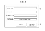
FIG. 2 is a diagram of an exemplary search condition input screen;
FIG. 3A is a diagram of an exemplary new examination input screen;
FIG. 3B is a diagram of an exemplary new examination input screen;
FIG. 3C is a diagram of an exemplary new examination input screen;
FIG. 4 is a diagram of an exemplary imaging screen;
FIG. 5 is a flowchart according to a first embodiment; and
FIG. 6 is a flowchart according to a second embodiment.
DESCRIPTION OF THE EMBODIMENTS
Some embodiments of the present invention will be described hereinafter in detail with reference to the drawings. In the embodiments described herein, an exemplary case using X-rays as radiation rays will be described. The radiation rays, however, are not limited to X-rays and may be, for example, electromagnetic waves, α-rays, β-rays, and γ-rays.
First Embodiment
FIG. 1 is a diagram of an exemplary configuration of a radiography system (hereinafter referred to as X-ray imaging system) according to an embodiment of the present invention.
In the X-ray imaging system, an X-ray imaging device 1, a radiology information system (RIS) 12, a PACS (image server) 13, and an HIS (hospital information system) 11 are connected. These devices are connected through a communication unit 15 including a local area network (LAN) and a wide area network (WAN). These devices each include one or a plurality of computers. Each computer includes a main control unit, such as a CPU, and a storing unit, such as a read only memory (ROM) and a random access memory (RAM). Each computer may also include a communication unit, such as a network card, and an input/output unit, such as a keyboard, a display, and a touch panel. These units are connected through a bus or the like, and are controlled by execution, by the main control unit, of a program stored in the storing unit.
The X-ray imaging device 1 includes an imaging device display section 2, an imaging device operation section 3, an imaging device control section 5, and an X-ray generating device control section 4.
The X-ray generating device control section 4 is connected through a cable 9 to an X-ray generation section in order to control X-ray emission from the X-ray generation section 8. Here, the X-ray generation section 8 (8 a, 8 b) functions as a radiation ray generation section. The X-ray generation section 8 is achieved by, for example, an X-ray tube and emits X-rays toward a subject (for example, a specific region of a patient).
The imaging device operation section 3 provides centralized control over processing in the X-ray imaging device 1. The imaging device display section 2 is achieved by, for example, a liquid crystal display and displays various types of information for an operator (for example, a radiographer and a doctor). The imaging device operation section 3 is achieved by, for example, a mouse and an operation button and allows the operator to input various instructions into the device. Note that, alternatively, the imaging device display section 2 and the imaging device operation section 3 may be achieved by a touch panel that combines the imaging device display section 2 and the imaging device operation section 3.
The X-ray imaging device 1 is connected through a cable 10 to an X-ray detector 7 (7 a, 7 b), such that electrical power, an image signal, a control signal, and the like are given and received by the X-ray imaging device 1 and the X-ray detector 7 through the cable 10.
The X-ray detector 7 functions as a detector to detect X-rays transmitted through the subject and to acquire an X-ray image (a radiation ray image) based on the subject. In other words, the X-ray generation section 8 and the X-ray detector 7 operate in a coordinated manner to achieve an X-ray imaging section. Here, the X-ray detector 7 is installed on an imaging table 6 (6 a, 6 b) in a standing position and a lying position.
An exemplary configuration of the X-ray imaging system has been described. It should be noted that the configuration illustrated in FIG. 1 is just an example, and may be changed as appropriate. For example, in FIG. 1, the X-ray imaging device 1 is connected to the various devices through the communication unit 15, but the X-ray imaging device 1 does not have to be connected to such devices.
A processing sequence of the X-ray imaging system illustrated in FIG. 1 for capturing an X-ray image will now be described in a sequence of an examination.
The X-ray imaging device 1 allows the imaging device display section 2 to display a search condition input screen illustrated in FIG. 2. The search condition input screen includes a patient/examination information input section 120, an examination acquisition button 121, and a cancel button, as illustrate in FIG. 2.
For acquiring an examination from the RIS, patient information (a patient name, a patient ID, and the like) and examination information (an examination ID, examination date and time, and the like) for the examination to be performed are input into the patient/examination information input section 120. Once the information is input and, then, the examination acquisition button 121 is pressed, the X-ray imaging device notifies, through the network, the RIS 12 of an examination acquisition request including a search condition that has been input from the search condition input screen. Upon receiving the examination acquisition request, the RIS 12 returns to the X-ray imaging device 1 an examination that matches the search condition.
The X-ray imaging device 1, having acquired the examination from the RIS 12, allows the imaging device display section 2 to display a new examination input screen illustrated in FIGS. 3A to 3C. As illustrated in FIG. 3A, the new examination input screen includes a patient information input area 101, a patient information enter button 102, a requested-examination list 103, a patient information display area 104, an imaging information display area 105, an imaging information input button 106, and an examination start button 107.
In the requested-examination list 103, the examination acquired from the RIS 12 is displayed in a list form. When any examination from the requested-examination list 103 is selected, patient information (a patient ID, a patient name, a birth date, and the like) corresponding to a selected patient is displayed in the patient information display area 104 as illustrated in FIG. 3B. In the imaging information display area 105, an examination ID is displayed, and in an area directly below the examination ID, imaging information corresponding to the examination ID is displayed. The imaging information is received from the RIS 12 as described above. In a case with FIG. 3B, an imaging method button 109 (a chest front button 109 a, a chest side button 109 b) corresponding to the imaging information is positioned. Upon pressing of the imaging information input button 106, an imaging information input area is displayed as illustrated in FIG. 3C to allow addition of a further imaging method.
The operator checks the patient information and the imaging information and, then, presses the examination start button 107. This determines the examination to be performed.
Following the pressing of the examination start button 107, the X-ray imaging device 1 allows the imaging device display section 2 to display an imaging screen illustrated in FIG. 4. The imaging screen is a screen used for imaging.
The imaging screen basically includes display areas similar to those of the new examination input screen described with reference to FIGS. 3A to 3C. As additional display areas, an image display area 110, a message area 111, an image processing setting area 112, and an examination end button 113 are included as illustrated in FIG. 4.
In the imaging screen, when displayed, the imaging method button 109 a, positioned uppermost in the imaging information display area 105, is selected by default. Following this, the X-ray imaging device 1 allows the imaging device control section 5 to send to the X-ray generating device control section 4 an imaging condition (a tube voltage, a tube current, an irradiation time, and the like) set in correspondence with the imaging method button (that is, an imaging method thereof). Then, the imaging device control section 5 controls the X-ray detector 7 in accordance with the imaging condition in preparation for imaging.
When the preparation is completed, the X-ray imaging device 1 achieves a transition to a state in which imaging is possible. The message area 111, then, displays a “Ready message” to indicate the state in which the imaging is possible.
Subsequently, the operator checks the imaging method, performs setting of the imaging, and positions the patient. When a series of imaging preparations is completed, the operator references the message area 111 to confirm that the state in which the imaging is possible is indicated, and presses an X-ray emission switch (not shown). Then, the X-ray imaging device 1 allows the X-ray generation section 8 to emit X-rays toward a subject (a specific region of the patient), and allows the X-ray detector 7 to detect X-rays that have transmitted through the subject. This enables an X-ray image to be captured.
Once the imaging is finished, the X-ray imaging device 1 allows the imaging device control section 5 to acquire the captured image from the X-ray detector 7. The X-ray imaging device 1 also performs image processing on the captured and acquired image in accordance with a predetermined image processing condition. The predetermined image processing condition is defined in advance in correspondence with the imaging method.
When the image processing is finished, the X-ray imaging device 1 allows the captured image display area 110 to display the captured image that has been subjected to the image processing. In a case where it is desired that, for example, contrast of the captured image be changed, the operator operates a button for contrast, brightness, or the like provided in the image processing setting area 112. This allows the operator to perform additional image processing on the captured image displayed in the captured image display area 110. Here, if the operator presses the imaging method button 109 for which imaging has not been performed, the imaging condition and the image processing condition for the image are saved, and then subsequent imaging will start.
The operator repeats the procedure described above to perform imaging for all imaging methods in the imaging information display area 105. When the entire imaging is finished, the operator presses the examination end button 113. This completes a series of examinations, and the X-ray imaging device 1 again displays the search condition input screen. At this point in time, the X-ray imaging device 1 allows the imaging device control section 5 to output the captured image, the examination information, and the like to, for example, the PACS 13, a printer (not shown), the RIS 12, and a ROM within the X-ray imaging device 1. Note that in the RIS 12, the ROM, and the like, the captured image and the patient information are associated with each other and stored.
An operation of the X-ray imaging system according to the present embodiment will now be described with reference to a flowchart illustrated in FIG. 5.
With reference to FIG. 5, in step S301, a search condition for an examination to be acquired is input. In step S302, an examination that matches the search condition specified in step S301 is acquired from the RIS.
In step S303, whether the examination acquired from the RIS 12 matches an imaging preparation condition is confirmed. Here, the imaging preparation condition is a condition to confirm that there is one examination option to start with. The condition may be “that there is one examination that has been acquired.” If it is possible to perform more than one examination for an identical patient, the condition may be “that all examinations that have been acquired are for an identical patient.”
If the imaging preparation condition is satisfied, imaging preparation is performed in step S304. The imaging preparation includes the display of the imaging screen, the drive control of the X-ray detector 7, and the notification of the imaging condition to an X-ray generating device.
When the imaging preparation described above is completely finished, the state in which imaging is possible is achieved in step S305.
If the imaging preparation condition is not satisfied in step S303, then in step S306, an examination to be performed is selected from the requested-examination list, and an instruction to start the examination is issued to perform the imaging preparation.
As described above, according to a first embodiment, by setting a search condition such that the imaging preparation condition is satisfied, an operation to select an examination from the requested-examination list and an operation to issue an instruction to start the examination are eliminated. In addition, the preparation to start the examination is automatically performed to achieve a transition to the state in which the imaging is possible, facilitating performing of an examination.
As a unit for acquiring an examination, an example where communication with the RIS 12 is allowed through a network has been described. Alternatively, a method for acquiring an examination not through a network, for example, by input with a file, may be used. In addition, as a unit for searching, a unit for narrowing down the requested-examination list may be provided using, for example, a search field and a bar code reader, and the imaging preparation condition may be applied to a result of the narrowing down.
Second Embodiment
A second embodiment will now be described. As drive modes of an X-ray detector 7, an imaging mode and a standby mode, for example, are available. The imaging mode is a mode in which a voltage is applied to an image sensor so that an X-ray image can be acquired once X-rays are emitted. The standby mode is a mode in which a voltage application to the image sensor is stopped. In the present embodiment, a case will be described with reference to a flowchart illustrated in FIG. 6, in which the drive control of the X-ray detector 7 is performed in accordance with a result of the examination acquisition, so that a transition time to the state in which imaging is possible is reduced.
Steps S301, S302, and S303 are similar to the first embodiment, and, thus, the description thereof will not be repeated.
If the imaging preparation condition is not satisfied in step S303, whether the identical X-ray detector is used for imaging of all acquired examinations is confirmed in step S307. It is contemplated that a plurality of X-ray detectors is used for an examination, and, hence, the determination may be on the basis of whether the identical X-ray detector 7 is used for a beginning of the imaging of all acquired examinations.
If the identical X-ray detector 7 is used for all acquired examinations, an emission enabling signal (a driving signal) is sent to the X-ray detector 7 in step S308. Following this, the X-ray detector 7 applies a voltage to the image sensor and starts shifting to the imaging mode described above.
Then, in step S306, an examination to be performed is selected from the requested-examination list, and an instruction to start the examination is issued.
In this case, the drive control, which has been performed in step S308 on the X-ray detector 7 to the imaging mode, is skipped to simplify the imaging preparation in step S304. It should be noted that the procedures of the radiography control achieved in the first embodiment and the second embodiment described above may be performed by a computer that reads a computer program recorded in a computer readable recording medium and that functions as a radiography control apparatus.
Other Embodiments
Embodiments of the present invention can also be realized by a computer of a system or apparatus that reads out and executes computer executable instructions recorded on a storage medium (e.g., non-transitory computer-readable storage medium) to perform the functions of one or more of the above-described embodiment(s) of the present invention, and by a method performed by the computer of the system or apparatus by, for example, reading out and executing the computer executable instructions from the storage medium to perform the functions of one or more of the above-described embodiment(s). The computer may comprise one or more of a central processing unit (CPU), micro processing unit (MPU), or other circuitry, and may include a network of separate computers or separate computer processors. The computer executable instructions may be provided to the computer, for example, from a network or the storage medium. The storage medium may include, for example, one or more of a hard disk, a random-access memory (RAM), a read only memory (ROM), a storage of distributed computing systems, an optical disk (such as a compact disc (CD), digital versatile disc (DVD), or Blu-ray Disc (BD)™), a flash memory device, a memory card, and the like.
While the present invention has been described with reference to exemplary embodiments, it is to be understood that the invention is not limited to the disclosed exemplary embodiments. The scope of the following claims is to be accorded the broadest interpretation so as to encompass all such modifications and equivalent structures and functions.
This application claims the benefit of Japanese Patent Application No. 2012-135830, filed Jun. 15, 2012, which is hereby incorporated by reference herein in its entirety.

Claims (11)

What is claimed is:
1. A radiography control apparatus, comprising:
a search condition specifying unit configured to specify a search condition for acquiring an examination order;
an examination order acquiring unit configured to acquire the examination order based on the search condition through a network; and
an imaging preparation unit configured to determine whether the examination order acquired by the examination order acquiring unit corresponds to an imaging start condition or not, and shift an X-ray detector to an imaging mode in a case where the examination order corresponds to the imaging start condition.
2. The radiography control apparatus according to claim 1, wherein the imaging start condition is that there is one examination order that has been acquired.
3. The radiography control apparatus according to claim 1, wherein the imaging start condition is that examination orders that have been acquired are for an identical patient.
4. The radiography control apparatus according to claim 1, wherein the imaging start condition is that an identical image pickup device is used for imaging methods designated for all examination orders that have been acquired.
5. The radiography control apparatus according to claim 1,
further comprising an imaging screen for performing imaging in accordance with the examination order,
wherein the imaging preparation unit switches a screen display to the imaging screen as the imaging preparation processing.
6. The radiography control apparatus according to claim 1, wherein
an imaging method is designated for the examination order, and
the imaging preparation unit starts an initial drive of a detector to be used for the imaging method, so that a transition to a radiation ray accumulation standby state is achieved.
7. The radiography control apparatus according to claim 1,
further comprising an imaging condition notification unit configured to notify a radiation ray generating device of an imaging condition,
wherein the imaging preparation unit allows the imaging condition notification unit to notify the radiation ray generating device of an imaging condition for an imaging method defined by the examination order.
8. The radiography control apparatus according to claim 1, further comprising a display control unit configured to allow a display unit to display an examination order selection screen for an operator to select an examination order in a case where the result of the acquisition by the examination order acquiring unit does not satisfy the imaging start condition.
9. The radiography control apparatus according to claim 8,
wherein, even when the result of the acquisition by the examination order acquiring unit does not satisfy the imaging start condition, the imaging preparation unit performs the imaging preparation processing in a case where an identical image pickup device is to be used for imaging for imaging methods designated for all examination orders that have been acquired.
10. A radiography control method, comprising:
specifying, by a search condition specifying unit, a search condition for acquiring an examination order;
acquiring, by an examination order acquiring unit, an examination order based on the search condition through a network; and
determining, by an imaging preparation unit, whether the examination order acquired by the examination order acquiring unit corresponds to an imaging start condition or not, and shift an X-ray detector to an imaging mode in a case where the examination order corresponds to the imaging start condition.
11. A non-transitory computer readable recording medium storing a program for enabling a computer to perform control operations of a radiography control apparatus, comprising:
specifying a search condition for acquiring an examination order;
acquiring the examination order based on the search condition through a networks; and
determining whether the examination order acquired by the acquiring corresponds to an imaging start condition or not, and shift an X-ray detector to an imaging mode in a case where the examination order corresponds to the imaging start condition.
US13/915,365 2012-06-15 2013-06-11 Radiography control apparatus and radiography control method Active 2034-05-08 US9313868B2 (en)

Applications Claiming Priority (2)

Application Number Priority Date Filing Date Title
JP2012135830A JP6132483B2 (en) 2012-06-15 2012-06-15 Radiography control apparatus and method
JP2012-135830 2012-06-15

Publications (2)

Publication Number Publication Date
US20130336457A1 US20130336457A1 (en) 2013-12-19
US9313868B2 true US9313868B2 (en) 2016-04-12

Family

ID=49755917

Family Applications (1)

Application Number Title Priority Date Filing Date
US13/915,365 Active 2034-05-08 US9313868B2 (en) 2012-06-15 2013-06-11 Radiography control apparatus and radiography control method

Country Status (2)

Country Link
US (1) US9313868B2 (en)
JP (1) JP6132483B2 (en)

Cited By (3)

* Cited by examiner, † Cited by third party
Publication number Priority date Publication date Assignee Title
US20160081642A1 (en) * 2014-09-22 2016-03-24 Fujifilm Corporation Console device of portable type, control method and radiographic imaging system
US20160081650A1 (en) * 2014-09-22 2016-03-24 Fujifilm Corporation Console device of portable type, control method and radiographic imaging system
US20170281113A1 (en) * 2016-04-01 2017-10-05 Canon Kabushiki Kaisha Radiographing system, mobile terminal, radiographing apparatus, radiographing method, and storage medium

Families Citing this family (2)

* Cited by examiner, † Cited by third party
Publication number Priority date Publication date Assignee Title
JP6072100B2 (en) * 2015-01-30 2017-02-01 キヤノン株式会社 Radiation imaging system, control method, control method, and program
JP7375525B2 (en) 2019-12-23 2023-11-08 株式会社島津製作所 Patient authentication system and patient authentication method

Citations (2)

* Cited by examiner, † Cited by third party
Publication number Priority date Publication date Assignee Title
JP2006081761A (en) 2004-09-16 2006-03-30 Hitachi Medical Corp Image display method in radiographic apparatus
US20060242552A1 (en) * 2005-04-26 2006-10-26 Hirokazu Tanaka Mobile radiography apparatus, control method thereof, and program

Family Cites Families (5)

* Cited by examiner, † Cited by third party
Publication number Priority date Publication date Assignee Title
JP2003033342A (en) * 2001-07-24 2003-02-04 Canon Inc X-ray photographing apparatus, x-ray photographing system, x-ray photographing control method, storage medium, and program
JP3788510B2 (en) * 2002-03-20 2006-06-21 コニカミノルタホールディングス株式会社 Medical image apparatus, display screen transition method and screen transition program in the apparatus
JP2008154719A (en) * 2006-12-22 2008-07-10 Konica Minolta Medical & Graphic Inc Radiographic imaging system, control device, and radiation image detecting device
JP5132182B2 (en) * 2007-04-25 2013-01-30 キヤノン株式会社 MEDICAL EXAMINATION SYSTEM AND ITS PROCESSING METHOD, PROGRAM, AND STORAGE MEDIUM
JP5620692B2 (en) * 2010-02-22 2014-11-05 キヤノン株式会社 Radiation imaging system, control device and processing method

Patent Citations (2)

* Cited by examiner, † Cited by third party
Publication number Priority date Publication date Assignee Title
JP2006081761A (en) 2004-09-16 2006-03-30 Hitachi Medical Corp Image display method in radiographic apparatus
US20060242552A1 (en) * 2005-04-26 2006-10-26 Hirokazu Tanaka Mobile radiography apparatus, control method thereof, and program

Cited By (6)

* Cited by examiner, † Cited by third party
Publication number Priority date Publication date Assignee Title
US20160081642A1 (en) * 2014-09-22 2016-03-24 Fujifilm Corporation Console device of portable type, control method and radiographic imaging system
US20160081650A1 (en) * 2014-09-22 2016-03-24 Fujifilm Corporation Console device of portable type, control method and radiographic imaging system
US10039509B2 (en) * 2014-09-22 2018-08-07 Fujifilm Corporation Console device of portable type, control method and radiographic imaging system
US10045751B2 (en) * 2014-09-22 2018-08-14 Fujifilm Corporation Console device of portable type, control method and radiographic imaging system
US20170281113A1 (en) * 2016-04-01 2017-10-05 Canon Kabushiki Kaisha Radiographing system, mobile terminal, radiographing apparatus, radiographing method, and storage medium
US10561388B2 (en) * 2016-04-01 2020-02-18 Canon Kabushiki Kaisha Radiographing system, mobile terminal, radiographing apparatus, radiographing method, and storage medium

Also Published As

Publication number Publication date
US20130336457A1 (en) 2013-12-19
JP6132483B2 (en) 2017-05-24
JP2014000132A (en) 2014-01-09

Similar Documents

Publication Publication Date Title
JP6079850B2 (en) Console and radiographic imaging system
US11020080B2 (en) Radiographic image capturing apparatus, radiographic image capturing system, control method of radiographic image capturing apparatus, and control program of radiographic image capturing apparatus
US9131593B2 (en) Radiation imaging control apparatus, radiation imaging system, and storage medium
US10630879B2 (en) Imaging control device, imaging apparatus, imaging control system, image display apparatus, imaging control method, information processing method, and program
US10561388B2 (en) Radiographing system, mobile terminal, radiographing apparatus, radiographing method, and storage medium
US9313868B2 (en) Radiography control apparatus and radiography control method
US10405819B2 (en) Imaging control apparatus, imaging control system, and imaging control method
US11047809B2 (en) Radiation imaging system, radiation imaging method, control apparatus, and computer-readable medium
US20210280300A1 (en) Medical information processing system, medical information processing method, and storage medium
US10891733B2 (en) Radiographing system, radiographing method, control apparatus, and storage medium
WO2017141498A1 (en) Radiographic imaging system, medical image output system and output device
US10485504B2 (en) Radiographing system for obtaining a dose index from a generated composition image
CN109843177B (en) Radiation imaging system, control method and control device thereof, and medium
US10624605B2 (en) Radiation imaging control apparatus, method of controlling the same, and non-transitory computer-readable storage medium
US11298094B2 (en) Radiography system, portable information terminal, radiography method, and computer-readable storage medium
US20230005105A1 (en) Radiation imaging system, image processing method, and storage medium
US11538187B2 (en) Radiographic system, radiographic method, and storage medium
US10444377B2 (en) Radiation imaging system, radiation imaging apparatus, radiation imaging method, and computer-readable medium
JP2011000185A (en) Medical examination instrument, medical examination processing method, and program
US20240248220A1 (en) Image processing apparatus, radiation imaging system, image processing method, and non-transitory computer-readable storage medium
US20240252134A1 (en) Radiography apparatus, control method therefor, and storage medium
US20240282433A1 (en) Information processing apparatus, radiation imaging system, information processing method, and non-transitory computer-readable storage medium
US20210043305A1 (en) Medical image diagnosis system, medical image processing method, and storage medium
US20240201921A1 (en) Information processing apparatus, information processing method, radiation imaging system, and storage medium
JP2014146381A (en) Medical inspection device and method for controlling the same, medical inspection system and program

Legal Events

Date Code Title Description
AS Assignment

Owner name: CANON KABUSHIKI KAISHA, JAPAN

Free format text: ASSIGNMENT OF ASSIGNORS INTEREST;ASSIGNOR:ARIMA, KEISUKE;REEL/FRAME:031294/0292

Effective date: 20130607

STCF Information on status: patent grant

Free format text: PATENTED CASE

MAFP Maintenance fee payment

Free format text: PAYMENT OF MAINTENANCE FEE, 4TH YEAR, LARGE ENTITY (ORIGINAL EVENT CODE: M1551); ENTITY STATUS OF PATENT OWNER: LARGE ENTITY

Year of fee payment: 4

MAFP Maintenance fee payment

Free format text: PAYMENT OF MAINTENANCE FEE, 8TH YEAR, LARGE ENTITY (ORIGINAL EVENT CODE: M1552); ENTITY STATUS OF PATENT OWNER: LARGE ENTITY

Year of fee payment: 8