US9312745B2 - Universal power supply system - Google Patents

Universal power supply system Download PDF

Info

Publication number
US9312745B2
US9312745B2 US13/708,992 US201213708992A US9312745B2 US 9312745 B2 US9312745 B2 US 9312745B2 US 201213708992 A US201213708992 A US 201213708992A US 9312745 B2 US9312745 B2 US 9312745B2
Authority
US
United States
Prior art keywords
power supply
power
board mounted
supply system
terminal
Prior art date
Legal status (The legal status is an assumption and is not a legal conclusion. Google has not performed a legal analysis and makes no representation as to the accuracy of the status listed.)
Active, expires
Application number
US13/708,992
Other versions
US20140159497A1 (en
Inventor
Wei-Dar Chen
Chung-Wei Yang
Current Assignee (The listed assignees may be inaccurate. Google has not performed a legal analysis and makes no representation or warranty as to the accuracy of the list.)
Acbel Polytech Inc
Original Assignee
Acbel Polytech Inc
Priority date (The priority date is an assumption and is not a legal conclusion. Google has not performed a legal analysis and makes no representation as to the accuracy of the date listed.)
Filing date
Publication date
Application filed by Acbel Polytech Inc filed Critical Acbel Polytech Inc
Priority to US13/708,992 priority Critical patent/US9312745B2/en
Assigned to ACBEL POLYTECH INC. reassignment ACBEL POLYTECH INC. ASSIGNMENT OF ASSIGNORS INTEREST (SEE DOCUMENT FOR DETAILS). Assignors: CHEN, WEI-DAR, YANG, CHUNG-WEI
Publication of US20140159497A1 publication Critical patent/US20140159497A1/en
Application granted granted Critical
Publication of US9312745B2 publication Critical patent/US9312745B2/en
Active legal-status Critical Current
Adjusted expiration legal-status Critical

Links

Images

Classifications

    • HELECTRICITY
    • H02GENERATION; CONVERSION OR DISTRIBUTION OF ELECTRIC POWER
    • H02MAPPARATUS FOR CONVERSION BETWEEN AC AND AC, BETWEEN AC AND DC, OR BETWEEN DC AND DC, AND FOR USE WITH MAINS OR SIMILAR POWER SUPPLY SYSTEMS; CONVERSION OF DC OR AC INPUT POWER INTO SURGE OUTPUT POWER; CONTROL OR REGULATION THEREOF
    • H02M1/00Details of apparatus for conversion
    • H02M1/32Means for protecting converters other than automatic disconnection
    • GPHYSICS
    • G06COMPUTING; CALCULATING OR COUNTING
    • G06FELECTRIC DIGITAL DATA PROCESSING
    • G06F1/00Details not covered by groups G06F3/00 - G06F13/00 and G06F21/00
    • G06F1/16Constructional details or arrangements
    • G06F1/18Packaging or power distribution
    • G06F1/183Internal mounting support structures, e.g. for printed circuit boards, internal connecting means
    • G06F1/188Mounting of power supply units
    • GPHYSICS
    • G06COMPUTING; CALCULATING OR COUNTING
    • G06FELECTRIC DIGITAL DATA PROCESSING
    • G06F1/00Details not covered by groups G06F3/00 - G06F13/00 and G06F21/00
    • G06F1/26Power supply means, e.g. regulation thereof
    • G06F1/28Supervision thereof, e.g. detecting power-supply failure by out of limits supervision
    • Y10T307/707

Definitions

  • the present invention relates to a universal power supply system and more particularly to a power supply system for industrial computers or servers.
  • a conventional modular power system 50 has a housing 51 , a backboard module 52 , multiple AC-to-DC (AC/DC) power supply devices 53 and multiple board mounted DC power modules 54 .
  • AC/DC AC-to-DC
  • the housing 51 has a first opening and a second opening opposite to each other.
  • the backboard module 52 is mounted to the first opening of the housing 51 , and has multiple DC power and communication interfaces 521 and a monitoring circuit 522 .
  • Each DC power and communication interface 521 has a DC power input/output (I/O) port 521 a and a communication port 521 b .
  • the monitoring circuit 522 is electrically connected to each communication port 521 b .
  • the monitoring circuit has multiple enable terminals S EN1 , S EN2 , multiple current detection terminals I S1 , I S2 , and multiple critical current values and critical power values.
  • the AC/DC power supply devices 53 are mounted in the housing 51 through the second opening A DC power output terminal DC/OUT1, DC/OUT2 of each DC power supply device 53 is connected to the DC power I/O port 521 a of a corresponding DC power and communication interface 521 and is connected to the monitoring circuit 522 of the backboard module 52 through a communication connection port (IIC1, IIC2).
  • the board mounted DC power modules 54 are mounted inside the housing 51 through the second opening.
  • Each board mounted DC power module 54 has a terminal port, an enable terminal EN and a current output terminal I SENSE corresponding to the DC power and communication interface 521 of a corresponding backboard module 52 to acquire DC power outputted from a corresponding AC/DC power supply device 53 , converts the DC power into a DC power with a specific voltage level, and outputs the converted DC power.
  • the enable terminal EN and the current output terminal I SENSE are connected to the communication port 521 b of the DC power and communication interface 521 .
  • the monitoring circuit 522 compares a current outputted from each board mounted DC power module 54 with a predetermined critical current value. If the output current is greater than the critical current value, the monitoring circuit 522 controls a corresponding enable terminal S ENT , S EN2 to disable the over-current board mounted DC power module 54 so as to prevent the power system 50 from burning out due to the over-current situation.
  • the AC/DC power supply devices 53 mounted inside the housing 51 of the modular power supply system 50 may have an identical wattage or different wattages.
  • the backboard module 52 is collaborated with the board mounted DC power module 54 to output in series or in parallel a DC power supplied from the respective AC/DC power supply devices 53 and converted from the respective board mounted DC power module 54 .
  • the DC power of one of the board mounted DC power modules 54 may serve as backup power.
  • the monitoring circuit 522 of the backboard module 52 monitors if the current outputted from each board mounted DC power module 54 is in an over-current status when compared with a corresponding critical current value. If positive, the monitoring circuit 522 controls to disable the over-current board mounted DC power module 54 for over-current protection (OCP).
  • OCP over-current protection
  • the monitoring circuit 522 allows that the wattages of two AC/DC power supply devices are both 500 W during a parallel output (current share) mode when the modular power supply system 50 supplies 500 W DC power, or allows that each AC/DC power supply device outputs a 250 W DC power.
  • the monitoring circuit 522 basically sets up 500 W as a critical power value. Once one of the AC/DC power supply devices is faulty, the other AC/DC power supply device supplies 500 W DC power alone. Hence, when two AC/DC power supply devices have the same wattage in operation, the critical power value can be fixed.
  • the AC/DC power supply devices with different wattages satisfy the requirement and can be all mounted inside the housing.
  • the parallel output mode is not activated as the backboard module detects that the two AC/DC power supply devices supply power with different wattages (500 W, 875 W).
  • one of the AC/DC power supply devices is enabled as a master while the other AC/DC power supply device functions as a slave. The master supplies power while the slave does not but only serves as a backup power source. If the 875 W AC/DC power supply device is selected as the master and the critical power value is still 500 W, damage arising from the over-power condition is inevitable.
  • the power wattage or DC power specifications of the modular AC/DC power supply devices and the board mounted DC power modules used by the power supply manufacturers can be hardly identified from the appearance.
  • the modular power supply system assembled by the power supply manufacturers is thus prone to errors, such as a board mounted DC power module plugged in a wrong DC power I/O port of the backboard module.
  • the modular power supply system currently still replies on a customized backboard module preventing the production efficiency from being effectively increased.
  • An objective of the present invention is to provide a universal power supply system capable of being applicable to different board mounted DC power modules or AC/DC power supply devices used in the universal power supply system without redesigning a backboard module.
  • the universal power supply system has a housing, a backboard module, multiple AC/DC power supply devices and multiple board mounted DC power modules.
  • the backboard module is mounted to the housing and has multiple DC power and communication interfaces and a monitoring circuit.
  • Each DC power and communication interface has a DC power input and output (I/O) port.
  • the monitoring circuit is electrically connected to the DC power and communication interfaces and has multiple enable terminals, multiple current detection terminals, multiple specification identification terminals and a specification mapping table.
  • the specification mapping table is built in the monitoring circuit and stores multiple model numbers and multiple critical current values corresponding to the model numbers.
  • Each AC/DC power supply device has a DC power output terminal connected to the DC power I/O port of one of the DC power and communication interfaces.
  • the board mounted DC power modules are mounted inside the housing, and are plugged in corresponding DC power and communication interfaces of the backboard module.
  • Each board mounted DC power module has a specification setting circuit, a specification setting terminal, an enable terminal and a current output terminal.
  • the specification setting terminal is electrically connected to a corresponding specification identification terminal of the monitoring circuit.
  • the enable terminal is electronically connected to a corresponding enable terminal of the monitoring circuit.
  • the current output terminal is connected to a corresponding current detection terminal of the monitoring circuit.
  • the monitoring circuit reads a specification identification signal from the specification setting circuit of each board mounted DC power module, identifies a model number according to the specification identification signal, and maps to a corresponding critical current value in the specification mapping table.
  • the universal power supply system allows each board mounted DC power module therein having identical dimensions and appearance to further have a specification setting circuit.
  • the specification setting terminal When the board mounted DC power module is plugged in a backboard module, the specification setting terminal outputs a specification identification signal to the monitoring circuit of the backboard module.
  • the monitoring circuit can compare the specification identification signal to find a model number corresponding to the signal, and automatically sets a critical current value or a critical power value of each board mounted DC power module for over-current protection.
  • the backboard automatically detects the model numbers of the board mounted DC power modules supplying power, and automatically monitors if each board mounted DC power module exceeds its corresponding critical current value for OCP without redesigning the backboard module due to different board mounted DC power modules applied therein.
  • the universal power supply system has a housing, a backboard module, multiple AC/DC power supply devices and multiple board mounted DC power modules.
  • the backboard module is mounted to the housing, and has multiple DC power and communication interfaces and a monitoring circuit.
  • Each DC power and communication interface has a DC power input and output (I/O) port.
  • the monitoring circuit is electrically connected to the DC power and communication interfaces and has multiple enable terminals, multiple specification identification terminals and a specification mapping table.
  • the specification mapping table is built in the monitoring circuit and stores multiple model numbers and multiple critical power values corresponding to the model numbers.
  • Each AC/DC power supply device has a DC power output terminal, a specification setting circuit and a specification setting terminal.
  • the DC power output terminal is connected to the DC power I/O port of one of the DC power and communication interfaces.
  • the specification setting terminal is electrically connected to a corresponding specification identification terminal of the monitoring circuit.
  • the board mounted DC power modules are mounted inside the housing and are plugged in corresponding DC power and communication interfaces of the backboard module.
  • the universal power supply system allows each board mounted DC power module therein having identical dimensions and appearance to further have a specification setting circuit.
  • the specification setting terminal When the AC/DC power supply device is plugged in a backboard module, the specification setting terminal outputs a specification identification signal to the monitoring circuit of the backboard module.
  • the monitoring circuit can compare the specification identification signal to find a model number corresponding to the signal, and automatically sets a critical current value or a critical power value of each AC/DC power supply device for over-power protection.
  • the backboard automatically detects the model numbers of the AC/DC power supply devices supplying power, and automatically monitors if each AC/DC power supply device exceeds its corresponding critical power value for OPP without redesigning the backboard module due to different AC/DC power supply devices applied therein.
  • FIG. 1 is a partially exploded perspective view of a universal power supply system in accordance with the present invention
  • FIG. 2 is a functional block diagram of a first embodiment of the universal power supply system in FIG. 1 ;
  • FIG. 3 is a functional block diagram of a second embodiment of the universal power supply system in FIG. 1 ;
  • FIG. 4 is a circuit diagram of the universal power supply system in FIG. 2 ;
  • FIG. 5 is a first circuit diagram applicable to the universal power supply system in FIG. 2 or FIG. 3 ;
  • FIG. 6 is a second circuit diagram applicable to the universal power supply system in FIG. 2 or FIG. 3 ;
  • FIG. 7 is a third circuit diagram applicable to the universal power supply system in FIG. 2 or FIG. 3 ;
  • FIG. 8 is a fourth circuit diagram applicable to the universal power supply system in FIG. 2 or FIG. 3 ;
  • FIG. 9 is a perspective view of a conventional power supply system.
  • FIG. 10 is a functional block diagram of the conventional power supply system in FIG. 9 .
  • a first embodiment of a universal power supply system 10 in accordance with the present invention has a housing 11 , a backboard module 12 , multiple AC/DC power supply devices 13 and at least one board mounted DC power module 14 .
  • the housing 11 has a first opening and a second opening opposite to each other.
  • the backboard module 12 is mounted to the first opening of the housing 11 , and has at least one DC power and communication interface 121 and a monitoring circuit 122 .
  • Each one of the at least one DC power and communication interface 121 has a DC power I/O port 121 a and a communication port 121 b .
  • the monitoring circuit 122 is electrically connected to the at least one DC power and communication interface 121 and has at least one enable terminal S EN1 , S EN2 , at least one current detection terminal I S1 , I S2 , at least one specification identification terminal V ID1 , V ID2 and a specification mapping table.
  • the specification mapping table stores data associated with a model number, a voltage value and a critical current value corresponding to the model number.
  • the AC/DC power supply devices 13 are mounted in the housing 11 through the second opening A DC power output terminal DC/OUT1, DC/OUT2 of each DC power supply device 13 is connected to the DC power I/O port 121 a of a corresponding DC power and communication interface 121 and is connected to the monitoring circuit 122 of the backboard module 12 through a communication connection port (IIC1, IIC2).
  • the at least one board mounted DC power module 14 is mounted in the housing 11 through the second opening, and is plugged in at least one corresponding DC power and communication interface 121 of the backboard module 12 .
  • Each one of the at least one board mounted DC power module 14 has a specification setting circuit 143 , a specification setting terminal V 1 , V 2 , an enable terminal DD1_EN, DD2_EN, and a current output terminal DD1_Ise1, DD2_Ise2.
  • the specification setting terminal V 1 , V 2 is electrically connected to the specification identification terminals V ID1 , V ID2 of the monitoring circuit 122 .
  • the enable terminal DD1_EN, DD2_EN of the board mounted DC power module 14 is electronically connected to a corresponding enable terminal S EN1 , S EN2 of the monitoring circuit 122 .
  • the current output terminal DD1_Ise1, DD2_Ise2 is connected to a corresponding current detection terminal I S1 , I S2 .
  • each one of the at least one board mounted DC power module 14 has a controller 141 , a DC power output terminal DD1_Vout and a current output circuit.
  • the current output circuit has a current detector (resistor Rs) and a differential amplifier 142 .
  • Two input terminals of the differential amplifier 142 are connected to two ends of the current detector Rs, and the current detector Rs is connected in series with the DC power output terminal DD1_Vout and a DC power output port DD1 to detect the current outputted from the current output terminal DD1_Ise1 of the current board mounted DC power module 14 .
  • a second embodiment of a universal power supply system 10 in accordance with the present invention differs from the first embodiment in that each AC/DC power supply device 13 has a specification setting circuit and a specification setting terminal V 3 , V 4 , and the monitoring circuit 122 further has multiple specification identification terminals V ID3 , V ID4 to respectively identify model numbers of the AC/DC power supply devices 13 and uses each model number to map to a corresponding critical power value in the specification mapping table built in the monitoring circuit 122 .
  • the monitoring circuit can also just have the specification identification terminals V ID3 , V ID4 to determine the model number of each AC/DC power supply device 13 without further having the specification identification terminals V ID1 , V ID2 for determining the critical current value of each board mounted DC power module 14 .
  • the monitoring circuit 122 only considers the AC/DC power supply device(s) currently supplying power as target(s) to monitor, and selects the corresponding critical power value(s) to monitor the target(s).
  • the monitoring circuit 122 is only connected to one board mounted DC power module 14 .
  • the specification setting circuit 143 of the board mounted DC power module is a voltage divider circuit 143 with a top resistor R1 and a bottom resistor R2.
  • the voltage divider circuit 143 is connected to a reference voltage Vref and has a series connected node V1 connected to the specification identification terminal V ID1 .
  • the bottom resistor R2 of the voltage divider circuit can be externally connected to the voltage divider circuit.
  • the monitoring circuit 122 can compare the voltage of the specification identification terminal V ID1 with the voltages in the specification mapping table to find a model number, maps the model number to a corresponding critical current value, and sets it as the critical current value of the board mounted DC power module 14 .
  • each board mounted DC power module 14 is a voltage divider circuit having a top resistor and a bottom resistor R1/R2, R3/R2. Each voltage divider circuit is connected to an identical reference voltage Vref.
  • the monitoring circuit 122 ′ can read different voltages from the two specification identification terminals V ID1 , V ID2 and compare them with the voltages in the specification mapping table, and read corresponding critical current values and set them as the critical current values of the respective board mounted DC power modules 14 if matching voltages in the specification mapping table are found.
  • the critical current value of each board mounted DC power module 14 can be automatically set up as a monitoring point for OCP of the board mounted DC power module 14 .
  • the circuit diagram in FIG. 5 is also applicable to the second embodiment of the universal power supply system.
  • the specification mapping table built in the monitoring circuit 122 ′ further has multiple model numbers corresponding to various AC/DC power supply devices and multiple critical power values corresponding to the model numbers.
  • the specification setting circuit of each AC/DC power supply device 13 is also a voltage divider circuit. By setting an identical reference voltage and selecting a top resistor with a different resistance value, the monitoring circuit 122 ′ acquires the output voltage specified by each AC/DC power supply device, compares the output voltage with the voltages in the specification mapping table, reads a corresponding critical power value in the specification mapping table, and sets up as the critical power value of the AC/DC power supply device 13 if a matching voltage in the specification mapping table is found.
  • the critical power value of each AC/DC power supply device 13 can be automatically set up as a monitoring point for OPP.
  • the specification identification circuits 143 in the board mounted DC power modules 14 may be two identical voltage divider circuits respectively connected with different reference voltages Vref1, Vref2.
  • Each specification setting circuit 143 ′ has multiple voltage divider circuits respectively connected with multiple reference voltages Vref1, Vref2 with different high voltage levels and low voltage levels. Therefore, each specification setting circuit 143 ′ outputs multiple voltage signals with different voltage levels to the monitoring circuit 122 ′.
  • each specification identification terminal of the monitoring circuit 122 ′ also has multiple specification identification sub-terminals V ID11 and V ID12 , V ID21 and V ID22 respectively connected to the series connected nodes of the voltage divider circuits of the specification setting circuits 143 ′ to read a high voltage signal and a low voltage signal from each specification setting circuit 143 ′.
  • each specification setting circuit 143 ′ has two voltage divider circuits. Suppose that Vref1>Vref2.
  • the two specification identification terminals V ID11 and V ID12 respectively read a high voltage signal and a low voltage interpreted as logic 1 and 0 from one of the two specification setting circuits 143 ′ and the two specification identification terminals V ID21 and V ID22 read a low voltage signal and a high voltage signal interpreted as logic 0 and 1 from the other specification setting circuit 143 ′.
  • the monitoring circuit 122 ′ can identify the model number of each board mounted DC power module according to the voltage signals of the specification identification terminals.
  • Each specification setting circuit 143 is integrated in the controller 141 a of a corresponding board mounted DC power module 14 .
  • the controller 141 a is connected to the specification setting terminals V1, V2 and is built in with specification data, which can be transmitted to the monitoring circuit 122 ′ in the form of PM BUS signals for the monitoring circuit 122 ′ to directly acquire the specification data, determine a model number of the current board mounted DC power module 14 , and read a critical current value in the specification mapping table.
  • the specification setting circuit of each AC/DC power supply device 13 is integrated in a corresponding secondary controller.
  • the secondary controller is connected to the specification setting terminals V3, V4, and is built in with specification data, which can be transmitted to the monitoring circuit 122 ′′ in the form of PM BUS signals and IIC signals for the monitoring circuit 122 ′ to directly acquire the specification data, determine a model number of the current board mounted DC power module 14 , and read a critical power value in the specification mapping table. A minimum of all the retrieved critical power values is taken as a critical power value for monitoring over-power condition.
  • the monitoring circuit can detect the AC/DC power supply device currently supplying power, the critical power value can be read from the specification mapping table according to the model number and is taken as a monitoring point for OPP.
  • the monitoring circuit uses the model number of one of the AC/DC power supply devices to set up a critical power value corresponding to the AC/DC power supply device from the specification mapping table as a monitoring point for OPP.
  • the monitoring circuit When the universal power supply system has an 875 W AC/DC power supply device and a 500 W AC/DC power supply device and the 875 W AC/DC power supply device is selected as the master, the monitoring circuit then reads the model number of the 875 W AC/DC power supply device and sets up critical power value corresponding to the 875 W AC/DC power supply device from the specification mapping table as a monitoring point for OPP.
  • the monitoring circuit reads the model number of the 500 W AC/DC power supply device and sets up critical power value corresponding to the 500 W AC/DC power supply device from the specification mapping table as a monitoring point for OPP to protect the 500 W AC/DC power supply device.
  • the back board module can automatically detect the model numbers of all the board mounted DC power modules and set up the corresponding critical current value for each board mounted DC power module as a monitoring point for OCP to monitor if the board mounted DC power module outputs a current over a corresponding critical current value. It is unnecessary for the backboard module to be redesigned when different board mounted DC power modules are applied and a foolproof function can be provided.
  • the backboard module can automatically detect the model numbers of all the AC/DC power supply devices and set up the corresponding critical power value for each AC/DC power supply module as a monitoring point for OPP to monitor if the AC/DC power supply device outputs a power over a corresponding critical current value. It is unnecessary for the backboard module to be redesigned when different AC/DC power supply devices are applied and a foolproof function can be provided.

Abstract

A universal power supply system allows each board mounted DC power module or each AC/DC power supply device therein having identical dimensions and appearance to further have a specification setting circuit. When the board mounted DC power module or the AC/DC power supply device is plugged in a backboard module, the specification setting terminal outputs a specification identification signal to a monitoring circuit of the backboard module. As built in with a specification mapping table, the monitoring circuit can compare the specification identification signal to find a model number corresponding to the signal, and automatically sets a critical current value or critical power value of each board mounted DC power module for over-current protection or over-power protection. Accordingly, the universal power supply system can be adapted to different board mounted DC power modules or AC/DC power supply devices without redesigning the backboard module.

Description

BACKGROUND OF THE INVENTION
1. Field of the Invention
The present invention relates to a universal power supply system and more particularly to a power supply system for industrial computers or servers.
2. Description of the Related Art
Regular industrial computers or servers should be able to sustain long-time operation and therefore require operating power supplied from power supply systems with high power or redundant power. Because industrial computers or servers produced by computer manufacturers may have different power specifications, in response to such concern, manufacturers of regular power supply systems provide a modular power supply system. With reference to FIGS. 9 and 10, a conventional modular power system 50 has a housing 51, a backboard module 52, multiple AC-to-DC (AC/DC) power supply devices 53 and multiple board mounted DC power modules 54.
The housing 51 has a first opening and a second opening opposite to each other.
The backboard module 52 is mounted to the first opening of the housing 51, and has multiple DC power and communication interfaces 521 and a monitoring circuit 522. Each DC power and communication interface 521 has a DC power input/output (I/O) port 521 a and a communication port 521 b. The monitoring circuit 522 is electrically connected to each communication port 521 b. The monitoring circuit has multiple enable terminals SEN1, SEN2, multiple current detection terminals IS1, IS2, and multiple critical current values and critical power values.
The AC/DC power supply devices 53 are mounted in the housing 51 through the second opening A DC power output terminal DC/OUT1, DC/OUT2 of each DC power supply device 53 is connected to the DC power I/O port 521 a of a corresponding DC power and communication interface 521 and is connected to the monitoring circuit 522 of the backboard module 52 through a communication connection port (IIC1, IIC2).
The board mounted DC power modules 54 are mounted inside the housing 51 through the second opening. Each board mounted DC power module 54 has a terminal port, an enable terminal EN and a current output terminal ISENSE corresponding to the DC power and communication interface 521 of a corresponding backboard module 52 to acquire DC power outputted from a corresponding AC/DC power supply device 53, converts the DC power into a DC power with a specific voltage level, and outputs the converted DC power. The enable terminal EN and the current output terminal ISENSE are connected to the communication port 521 b of the DC power and communication interface 521. The monitoring circuit 522 compares a current outputted from each board mounted DC power module 54 with a predetermined critical current value. If the output current is greater than the critical current value, the monitoring circuit 522 controls a corresponding enable terminal SENT, SEN2 to disable the over-current board mounted DC power module 54 so as to prevent the power system 50 from burning out due to the over-current situation.
The AC/DC power supply devices 53 mounted inside the housing 51 of the modular power supply system 50 may have an identical wattage or different wattages. According to a power supply demand, the backboard module 52 is collaborated with the board mounted DC power module 54 to output in series or in parallel a DC power supplied from the respective AC/DC power supply devices 53 and converted from the respective board mounted DC power module 54. Alternatively, the DC power of one of the board mounted DC power modules 54 may serve as backup power. Furthermore, the monitoring circuit 522 of the backboard module 52 monitors if the current outputted from each board mounted DC power module 54 is in an over-current status when compared with a corresponding critical current value. If positive, the monitoring circuit 522 controls to disable the over-current board mounted DC power module 54 for over-current protection (OCP). Besides, as the backboard module 52 further provides over-power protection (OPP), the monitoring circuit 522 allows that the wattages of two AC/DC power supply devices are both 500 W during a parallel output (current share) mode when the modular power supply system 50 supplies 500 W DC power, or allows that each AC/DC power supply device outputs a 250 W DC power. The monitoring circuit 522 basically sets up 500 W as a critical power value. Once one of the AC/DC power supply devices is faulty, the other AC/DC power supply device supplies 500 W DC power alone. Hence, when two AC/DC power supply devices have the same wattage in operation, the critical power value can be fixed.
Because of a standardized design, when the modular power supply system 50 is repaired or the modular power supply system 50 with various wattages is built, the AC/DC power supply devices with different wattages satisfy the requirement and can be all mounted inside the housing. Hence, when the modular power supply system 50 is repaired, if one of the AC/DC power supply devices with 500 W is replaced by an 875 W AC/DC power supply device, the parallel output mode is not activated as the backboard module detects that the two AC/DC power supply devices supply power with different wattages (500 W, 875 W). Instead, one of the AC/DC power supply devices is enabled as a master while the other AC/DC power supply device functions as a slave. The master supplies power while the slave does not but only serves as a backup power source. If the 875 W AC/DC power supply device is selected as the master and the critical power value is still 500 W, damage arising from the over-power condition is inevitable.
As the AC/DC power supply devices and the board mounted DC power modules used by the modular power supply system are modularly designed, power supply manufacturers no longer need to redesign the corresponding circuits or circuit boards. All it needs is just to customize the backboard module based on the demands of different power wattages or types of power outputs.
However, the power wattage or DC power specifications of the modular AC/DC power supply devices and the board mounted DC power modules used by the power supply manufacturers can be hardly identified from the appearance. As a consequence, the modular power supply system assembled by the power supply manufacturers is thus prone to errors, such as a board mounted DC power module plugged in a wrong DC power I/O port of the backboard module. Additionally, the modular power supply system currently still replies on a customized backboard module preventing the production efficiency from being effectively increased.
SUMMARY OF THE INVENTION
An objective of the present invention is to provide a universal power supply system capable of being applicable to different board mounted DC power modules or AC/DC power supply devices used in the universal power supply system without redesigning a backboard module.
To achieve the foregoing objective, the universal power supply system has a housing, a backboard module, multiple AC/DC power supply devices and multiple board mounted DC power modules.
The backboard module is mounted to the housing and has multiple DC power and communication interfaces and a monitoring circuit.
Each DC power and communication interface has a DC power input and output (I/O) port.
The monitoring circuit is electrically connected to the DC power and communication interfaces and has multiple enable terminals, multiple current detection terminals, multiple specification identification terminals and a specification mapping table.
The specification mapping table is built in the monitoring circuit and stores multiple model numbers and multiple critical current values corresponding to the model numbers.
The AC/DC power supply devices at an input side are mounted inside the housing. Each AC/DC power supply device has a DC power output terminal connected to the DC power I/O port of one of the DC power and communication interfaces.
The board mounted DC power modules are mounted inside the housing, and are plugged in corresponding DC power and communication interfaces of the backboard module. Each board mounted DC power module has a specification setting circuit, a specification setting terminal, an enable terminal and a current output terminal.
The specification setting terminal is electrically connected to a corresponding specification identification terminal of the monitoring circuit.
The enable terminal is electronically connected to a corresponding enable terminal of the monitoring circuit.
The current output terminal is connected to a corresponding current detection terminal of the monitoring circuit.
The monitoring circuit reads a specification identification signal from the specification setting circuit of each board mounted DC power module, identifies a model number according to the specification identification signal, and maps to a corresponding critical current value in the specification mapping table.
From the foregoing, the universal power supply system allows each board mounted DC power module therein having identical dimensions and appearance to further have a specification setting circuit. When the board mounted DC power module is plugged in a backboard module, the specification setting terminal outputs a specification identification signal to the monitoring circuit of the backboard module. As built in with a specification mapping table, the monitoring circuit can compare the specification identification signal to find a model number corresponding to the signal, and automatically sets a critical current value or a critical power value of each board mounted DC power module for over-current protection. Accordingly, when all the board mounted DC power modules are plugged in the corresponding DC power I/O ports of the backboard module, the backboard automatically detects the model numbers of the board mounted DC power modules supplying power, and automatically monitors if each board mounted DC power module exceeds its corresponding critical current value for OCP without redesigning the backboard module due to different board mounted DC power modules applied therein.
Alternatively, the universal power supply system has a housing, a backboard module, multiple AC/DC power supply devices and multiple board mounted DC power modules.
The backboard module is mounted to the housing, and has multiple DC power and communication interfaces and a monitoring circuit.
Each DC power and communication interface has a DC power input and output (I/O) port.
The monitoring circuit is electrically connected to the DC power and communication interfaces and has multiple enable terminals, multiple specification identification terminals and a specification mapping table.
The specification mapping table is built in the monitoring circuit and stores multiple model numbers and multiple critical power values corresponding to the model numbers.
The AC/DC power supply devices at an input side are mounted inside the housing. Each AC/DC power supply device has a DC power output terminal, a specification setting circuit and a specification setting terminal.
The DC power output terminal is connected to the DC power I/O port of one of the DC power and communication interfaces.
The specification setting terminal is electrically connected to a corresponding specification identification terminal of the monitoring circuit.
The board mounted DC power modules are mounted inside the housing and are plugged in corresponding DC power and communication interfaces of the backboard module.
From the foregoing, the universal power supply system allows each board mounted DC power module therein having identical dimensions and appearance to further have a specification setting circuit. When the AC/DC power supply device is plugged in a backboard module, the specification setting terminal outputs a specification identification signal to the monitoring circuit of the backboard module. As built in with a specification mapping table, the monitoring circuit can compare the specification identification signal to find a model number corresponding to the signal, and automatically sets a critical current value or a critical power value of each AC/DC power supply device for over-power protection. Accordingly, when all the AC/DC power supply devices are plugged in the backboard module, the backboard automatically detects the model numbers of the AC/DC power supply devices supplying power, and automatically monitors if each AC/DC power supply device exceeds its corresponding critical power value for OPP without redesigning the backboard module due to different AC/DC power supply devices applied therein.
Other objectives, advantages and novel features of the invention will become more apparent from the following detailed description when taken in conjunction with the accompanying drawings.
BRIEF DESCRIPTION OF THE DRAWINGS
FIG. 1 is a partially exploded perspective view of a universal power supply system in accordance with the present invention;
FIG. 2 is a functional block diagram of a first embodiment of the universal power supply system in FIG. 1;
FIG. 3 is a functional block diagram of a second embodiment of the universal power supply system in FIG. 1;
FIG. 4 is a circuit diagram of the universal power supply system in FIG. 2;
FIG. 5 is a first circuit diagram applicable to the universal power supply system in FIG. 2 or FIG. 3;
FIG. 6 is a second circuit diagram applicable to the universal power supply system in FIG. 2 or FIG. 3;
FIG. 7 is a third circuit diagram applicable to the universal power supply system in FIG. 2 or FIG. 3;
FIG. 8 is a fourth circuit diagram applicable to the universal power supply system in FIG. 2 or FIG. 3;
FIG. 9 is a perspective view of a conventional power supply system; and
FIG. 10 is a functional block diagram of the conventional power supply system in FIG. 9.
DETAILED DESCRIPTION OF THE INVENTION
With reference to FIGS. 1 and 2, a first embodiment of a universal power supply system 10 in accordance with the present invention has a housing 11, a backboard module 12, multiple AC/DC power supply devices 13 and at least one board mounted DC power module 14.
The housing 11 has a first opening and a second opening opposite to each other.
The backboard module 12 is mounted to the first opening of the housing 11, and has at least one DC power and communication interface 121 and a monitoring circuit 122. Each one of the at least one DC power and communication interface 121 has a DC power I/O port 121 a and a communication port 121 b. The monitoring circuit 122 is electrically connected to the at least one DC power and communication interface 121 and has at least one enable terminal SEN1, SEN2, at least one current detection terminal IS1, IS2, at least one specification identification terminal VID1, VID2 and a specification mapping table. In the present embodiment, the specification mapping table stores data associated with a model number, a voltage value and a critical current value corresponding to the model number.
The AC/DC power supply devices 13 are mounted in the housing 11 through the second opening A DC power output terminal DC/OUT1, DC/OUT2 of each DC power supply device 13 is connected to the DC power I/O port 121 a of a corresponding DC power and communication interface 121 and is connected to the monitoring circuit 122 of the backboard module 12 through a communication connection port (IIC1, IIC2).
The at least one board mounted DC power module 14 is mounted in the housing 11 through the second opening, and is plugged in at least one corresponding DC power and communication interface 121 of the backboard module 12. Each one of the at least one board mounted DC power module 14 has a specification setting circuit 143, a specification setting terminal V1, V2, an enable terminal DD1_EN, DD2_EN, and a current output terminal DD1_Ise1, DD2_Ise2. The specification setting terminal V1, V2 is electrically connected to the specification identification terminals VID1, VID2 of the monitoring circuit 122. The enable terminal DD1_EN, DD2_EN of the board mounted DC power module 14 is electronically connected to a corresponding enable terminal SEN1, SEN2 of the monitoring circuit 122. The current output terminal DD1_Ise1, DD2_Ise2 is connected to a corresponding current detection terminal IS1, IS2. With reference to FIG. 4, each one of the at least one board mounted DC power module 14 has a controller 141, a DC power output terminal DD1_Vout and a current output circuit. The current output circuit has a current detector (resistor Rs) and a differential amplifier 142. Two input terminals of the differential amplifier 142 are connected to two ends of the current detector Rs, and the current detector Rs is connected in series with the DC power output terminal DD1_Vout and a DC power output port DD1 to detect the current outputted from the current output terminal DD1_Ise1 of the current board mounted DC power module 14.
With reference to FIG. 3, a second embodiment of a universal power supply system 10 in accordance with the present invention differs from the first embodiment in that each AC/DC power supply device 13 has a specification setting circuit and a specification setting terminal V3, V4, and the monitoring circuit 122 further has multiple specification identification terminals VID3, VID4 to respectively identify model numbers of the AC/DC power supply devices 13 and uses each model number to map to a corresponding critical power value in the specification mapping table built in the monitoring circuit 122. Additionally, the monitoring circuit can also just have the specification identification terminals VID3, VID4 to determine the model number of each AC/DC power supply device 13 without further having the specification identification terminals VID1, VID2 for determining the critical current value of each board mounted DC power module 14. However, the monitoring circuit 122 only considers the AC/DC power supply device(s) currently supplying power as target(s) to monitor, and selects the corresponding critical power value(s) to monitor the target(s).
With reference to FIG. 4, a circuit diagram of the first embodiment of the universal power supply system is shown. The monitoring circuit 122 is only connected to one board mounted DC power module 14. The specification setting circuit 143 of the board mounted DC power module is a voltage divider circuit 143 with a top resistor R1 and a bottom resistor R2. The voltage divider circuit 143 is connected to a reference voltage Vref and has a series connected node V1 connected to the specification identification terminal VID1. In the present embodiment, the bottom resistor R2 of the voltage divider circuit can be externally connected to the voltage divider circuit. In other words, one end of the top resistor R1 is connected to the reference voltage Vref, the other end of the top resistor R1 is connected to the specification setting terminal V1, the specification setting terminal V1 is further connected to one end of the externally connected bottom resistor R2, and the other end of the bottom resistor R2 is grounded. As the resistance values of the top resistor R1 and the bottom resistor R2 are fixed, the monitoring circuit 122 can compare the voltage of the specification identification terminal VID1 with the voltages in the specification mapping table to find a model number, maps the model number to a corresponding critical current value, and sets it as the critical current value of the board mounted DC power module 14.
With reference to FIG. 5, a first circuit diagram that is applicable to the first embodiment of the universal power supply system is shown. In comparison with the universal power supply system in FIG. 4, the universal power supply system in FIG. 5 further has one more board mounted DC power module 14. The specification setting circuit 143 of each board mounted DC power module 14 is a voltage divider circuit having a top resistor and a bottom resistor R1/R2, R3/R2. Each voltage divider circuit is connected to an identical reference voltage Vref. Given different resistance values of the top resistors R1, R3 in the two voltage divider circuits, the monitoring circuit 122′ can read different voltages from the two specification identification terminals VID1, VID2 and compare them with the voltages in the specification mapping table, and read corresponding critical current values and set them as the critical current values of the respective board mounted DC power modules 14 if matching voltages in the specification mapping table are found. Hence, the critical current value of each board mounted DC power module 14 can be automatically set up as a monitoring point for OCP of the board mounted DC power module 14.
Similarly, the circuit diagram in FIG. 5 is also applicable to the second embodiment of the universal power supply system. The specification mapping table built in the monitoring circuit 122′ further has multiple model numbers corresponding to various AC/DC power supply devices and multiple critical power values corresponding to the model numbers. The specification setting circuit of each AC/DC power supply device 13 is also a voltage divider circuit. By setting an identical reference voltage and selecting a top resistor with a different resistance value, the monitoring circuit 122′ acquires the output voltage specified by each AC/DC power supply device, compares the output voltage with the voltages in the specification mapping table, reads a corresponding critical power value in the specification mapping table, and sets up as the critical power value of the AC/DC power supply device 13 if a matching voltage in the specification mapping table is found. Hence, the critical power value of each AC/DC power supply device 13 can be automatically set up as a monitoring point for OPP.
To allow the monitoring circuit 122′ to identify a specification of each board mounted DC power module from the voltage of the specification identification terminal and to further set up a proper critical current value, with reference to FIG. 6, which is a second circuit diagram that is applicable to the first embodiment of the universal power supply system, the specification identification circuits 143 in the board mounted DC power modules 14 may be two identical voltage divider circuits respectively connected with different reference voltages Vref1, Vref2.
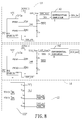
With reference to FIG. 7, a third circuit diagram that is applicable to the first embodiment of the universal power supply system is shown. Each specification setting circuit 143′ has multiple voltage divider circuits respectively connected with multiple reference voltages Vref1, Vref2 with different high voltage levels and low voltage levels. Therefore, each specification setting circuit 143′ outputs multiple voltage signals with different voltage levels to the monitoring circuit 122′. To correspond to the specification identification terminals of the specification setting circuits 143′, each specification identification terminal of the monitoring circuit 122′ also has multiple specification identification sub-terminals VID11 and VID12, VID21 and VID22 respectively connected to the series connected nodes of the voltage divider circuits of the specification setting circuits 143′ to read a high voltage signal and a low voltage signal from each specification setting circuit 143′. Given FIG. 7 as an example, each specification setting circuit 143′ has two voltage divider circuits. Suppose that Vref1>Vref2. The two specification identification terminals VID11 and VID12 respectively read a high voltage signal and a low voltage interpreted as logic 1 and 0 from one of the two specification setting circuits 143′ and the two specification identification terminals VID21 and VID22 read a low voltage signal and a high voltage signal interpreted as logic 0 and 1 from the other specification setting circuit 143′. Hence, the monitoring circuit 122′ can identify the model number of each board mounted DC power module according to the voltage signals of the specification identification terminals.
With reference to FIG. 8, a fourth circuit diagram that is applicable to the first embodiment of the universal power supply system is shown. Each specification setting circuit 143 is integrated in the controller 141 a of a corresponding board mounted DC power module 14. In other words, the controller 141 a is connected to the specification setting terminals V1, V2 and is built in with specification data, which can be transmitted to the monitoring circuit 122′ in the form of PM BUS signals for the monitoring circuit 122′ to directly acquire the specification data, determine a model number of the current board mounted DC power module 14, and read a critical current value in the specification mapping table. Likewise, the specification setting circuit of each AC/DC power supply device 13 is integrated in a corresponding secondary controller. In other words, the secondary controller is connected to the specification setting terminals V3, V4, and is built in with specification data, which can be transmitted to the monitoring circuit 122″ in the form of PM BUS signals and IIC signals for the monitoring circuit 122′ to directly acquire the specification data, determine a model number of the current board mounted DC power module 14, and read a critical power value in the specification mapping table. A minimum of all the retrieved critical power values is taken as a critical power value for monitoring over-power condition.
As the monitoring circuit can detect the AC/DC power supply device currently supplying power, the critical power value can be read from the specification mapping table according to the model number and is taken as a monitoring point for OPP. When the universal power supply system has two 500 W AC/DC power supply devices operated under the parallel output mode, the monitoring circuit uses the model number of one of the AC/DC power supply devices to set up a critical power value corresponding to the AC/DC power supply device from the specification mapping table as a monitoring point for OPP. When the universal power supply system has an 875 W AC/DC power supply device and a 500 W AC/DC power supply device and the 875 W AC/DC power supply device is selected as the master, the monitoring circuit then reads the model number of the 875 W AC/DC power supply device and sets up critical power value corresponding to the 875 W AC/DC power supply device from the specification mapping table as a monitoring point for OPP. On the other hand, when the 500 W AC/DC power supply device is selected as the master, the monitoring circuit reads the model number of the 500 W AC/DC power supply device and sets up critical power value corresponding to the 500 W AC/DC power supply device from the specification mapping table as a monitoring point for OPP to protect the 500 W AC/DC power supply device.
In sum, after all the board mounted DC power modules are plugged in the corresponding DC power I/O ports, the back board module can automatically detect the model numbers of all the board mounted DC power modules and set up the corresponding critical current value for each board mounted DC power module as a monitoring point for OCP to monitor if the board mounted DC power module outputs a current over a corresponding critical current value. It is unnecessary for the backboard module to be redesigned when different board mounted DC power modules are applied and a foolproof function can be provided. Besides, after all AC/DC power supply devices at the input side are connected to the backboard module, similarly, the backboard module can automatically detect the model numbers of all the AC/DC power supply devices and set up the corresponding critical power value for each AC/DC power supply module as a monitoring point for OPP to monitor if the AC/DC power supply device outputs a power over a corresponding critical current value. It is unnecessary for the backboard module to be redesigned when different AC/DC power supply devices are applied and a foolproof function can be provided.
Even though numerous characteristics and advantages of the present invention have been set forth in the foregoing description, together with details of the structure and function of the invention, the disclosure is illustrative only. Changes may be made in detail, especially in matters of shape, size, and arrangement of parts within the principles of the invention to the full extent indicated by the broad general meaning of the terms in which the appended claims are expressed.

Claims (20)

What is claimed is:
1. A universal power supply system comprising:
a housing;
a backboard module mounted to the housing, and having:
multiple DC power and communication interfaces, each having a DC power input and output (I/O) port; and
a monitoring circuit electrically connected to the DC power and communication interfaces and having:
multiple enable terminals;
multiple current detection terminals;
multiple specification identification terminals; and
a specification mapping table built therein and storing multiple model numbers and multiple critical current values corresponding to the model numbers;
multiple AC-to-DC (AC/DC) power supply devices at an input side mounted inside the housing, each AC/DC power supply device having a DC power output terminal connected to the DC power I/O port of one of the DC power and communication interfaces; and
multiple board mounted DC power modules mounted inside the housing, and plugged in corresponding DC power and communication interfaces of the backboard module, each board mounted DC power module having:
a specification setting circuit;
a specification setting terminal electrically connected to a corresponding specification identification terminal of the monitoring circuit;
an enable terminal electronically connected to a corresponding enable terminal of the monitoring circuit; and
a current output terminal connected to a corresponding current detection terminal of the monitoring circuit;
wherein the monitoring circuit reads a specification identification signal from the specification setting circuit of each board mounted DC power module, identifies a model number according to the specification identification signal and sets a critical current value for over-current protection of the respective board mounted DC power module to the critical current value in the specification mapping table corresponding to the identified model number.
2. The universal power supply system as claimed in claim 1, wherein the specification setting circuit of each board mounted DC power module has a voltage divider circuit connected to a reference voltage and having a series connected node being the specification setting terminal.
3. The universal power supply system as claimed in claim 2, wherein the voltage divider circuits of the respective board mounted DC power modules are identical, and the reference voltages connected to the voltage divider circuits of the respective board mounted DC power modules are different.
4. The universal power supply system as claimed in claim 2, wherein the voltage divider circuits of the respective board mounted DC power modules are different, and the reference voltages connected to the voltage divider circuits of the respective board mounted DC power modules are identical.
5. The universal power supply system as claimed in claim 4, wherein each voltage divider circuit of a corresponding board mounted DC power module has a top resistor and a bottom resistor, and the top resistors of the voltage divider circuits of the board mounted DC power modules have different resistance values.
6. The universal power supply system as claimed in claim 1, wherein
the specification setting terminal of each board mounted DC power module has multiple specification setting sub-terminals;
the specification setting circuit of each board mounted DC power module has multiple voltage divider circuits respectively connected to multiple reference voltages with different high voltage levels and low voltage levels, wherein each voltage divider circuit has a series connected node being a corresponding specification setting sub-terminal; and
each specification identification terminal of the monitoring circuit has multiple specification identification sub-terminals respectively connected to the series connected nodes of the voltage divider circuits of the specification setting circuits of the board mounted DC power modules.
7. The universal power supply system as claimed in claim 2, wherein the specification mapping table built in the monitoring circuit further has multiple voltage values corresponding to the respective model numbers.
8. The universal power supply system as claimed in claim 7, wherein when reading a specification identification signal of each specification identification terminal, the monitoring circuit compares the specification identification signal with the voltage values in the specification mapping table until a matching voltage value is found, then reads the model number corresponding to the matching voltage value, and sets the critical current value corresponding to the model number as a critical current value for the board mounted DC power module connected to the specification identification terminal.
9. The universal power supply system as claimed in claim 1, wherein
each board mounted DC power module has a controller connected to the specification setting terminals and built in with specification data; and
the specification setting circuit of the board mounted DC power module is integrated in the controller.
10. The universal power supply system as claimed in claim 9, wherein the monitoring circuit reads the specification data transmitted through each specification identification terminal thereof, compares the specification data with the model number in the specification mapping table until a matching model number is found, then sets the critical current value corresponding to the model number as a critical current value for the board mounted DC power module connected to the specification identification terminal.
11. A universal power supply system comprising:
a housing;
a backboard module mounted to the housing, and having:
multiple DC power and communication interfaces, each having a DC power input and output (I/O) port; and
a monitoring circuit electrically connected to the DC power and communication interfaces and having:
multiple enable terminals;
multiple specification identification terminals; and
a specification mapping table built therein and storing multiple model numbers and multiple critical power values corresponding to the model numbers;
multiple AC/DC power supply devices at an input side mounted inside the housing, each AC/DC power supply device having:
a DC power output terminal connected to the DC power I/O port of one of the DC power and communication interfaces;
a specification setting circuit; and
a specification setting terminal electrically connected to a corresponding specification identification terminal of the monitoring circuit;
multiple board mounted DC power modules mounted inside the housing, and plugged in corresponding DC power and communication interfaces of the backboard module.
12. The universal power supply system as claimed in claim 11, wherein the specification setting circuit of each AC/DC power supply device has a voltage divider circuit connected to a reference voltage and having a series connected node being the specification setting terminal.
13. The universal power supply system as claimed in claim 12, wherein the voltage divider circuits of the respective AC/DC power supply devices are identical, and the reference voltages connected to the voltage divider circuits of the respective AC/DC power supply devices are different.
14. The universal power supply system as claimed in claim 12, wherein the voltage divider circuits of the respective AC/DC power supply devices are different, and the reference voltages connected to the voltage divider circuits of the respective AC/DC power supply devices are identical.
15. The universal power supply system as claimed in claim 13, wherein each voltage divider circuit of a corresponding AC/DC power supply device has a top resistor and a bottom resistor, and the top resistors of the voltage divider circuits of the AC/DC power supply devices have different resistance values.
16. The universal power supply system as claimed in claim 11, wherein
the specification setting terminal of each AC/DC power supply device has multiple specification setting sub-terminals;
the specification setting circuit of each AC/DC power supply device has multiple voltage divider circuits respectively connected to multiple reference voltages with different high voltage levels and low voltage levels, wherein each voltage divider circuit has a series connected node being a corresponding specification setting sub-terminal; and
each specification identification terminal of the monitoring circuit has multiple specification identification sub-terminals respectively connected to the series connected nodes of the voltage divider circuits of the specification setting circuits of the AC/DC power supply devices.
17. The universal power supply system as claimed in claim 12, wherein the specification mapping table built in the monitoring circuit further has multiple voltage values corresponding to the respective model numbers.
18. The universal power supply system as claimed in claim 17, wherein when reading a specification identification signal of each specification identification terminal, the monitoring circuit compares the specification identification signal with the voltage values in the specification mapping table until a matching voltage value is found, then reads the model number corresponding to the matching voltage value, and sets the critical power value corresponding to the model number as a critical power value for the AC/DC power supply device connected to the specification identification terminal.
19. The universal power supply system as claimed in claim 11, wherein
each AC/DC power supply device has a secondary controller connected to the specification setting terminals and built in with specification data; and
the specification setting circuit of the AC/DC power supply device is integrated in the secondary controller.
20. The universal power supply system as claimed in claim 19, wherein the monitoring circuit reads the specification data transmitted through each specification identification terminal thereof, compares the specification data with the model number in the specification mapping table until a matching model number is found, then sets the critical power value corresponding to the model number as a critical power value for the AC/DC power supply device connected to the specification identification terminal.
US13/708,992 2012-12-08 2012-12-08 Universal power supply system Active 2034-12-08 US9312745B2 (en)

Priority Applications (1)

Application Number Priority Date Filing Date Title
US13/708,992 US9312745B2 (en) 2012-12-08 2012-12-08 Universal power supply system

Applications Claiming Priority (1)

Application Number Priority Date Filing Date Title
US13/708,992 US9312745B2 (en) 2012-12-08 2012-12-08 Universal power supply system

Publications (2)

Publication Number Publication Date
US20140159497A1 US20140159497A1 (en) 2014-06-12
US9312745B2 true US9312745B2 (en) 2016-04-12

Family

ID=50880168

Family Applications (1)

Application Number Title Priority Date Filing Date
US13/708,992 Active 2034-12-08 US9312745B2 (en) 2012-12-08 2012-12-08 Universal power supply system

Country Status (1)

Country Link
US (1) US9312745B2 (en)

Families Citing this family (10)

* Cited by examiner, † Cited by third party
Publication number Priority date Publication date Assignee Title
TW201727434A (en) * 2016-01-27 2017-08-01 光寶電子(廣州)有限公司 Method of integrating a server using alternating current power into a server system using direct current power and alternative junction device therefor
US9733686B1 (en) * 2016-02-03 2017-08-15 Dell Products L.P. Systems and methods for management controller enhanced power supply unit current sharing
CN105938325B (en) * 2016-04-05 2021-10-29 中国电力科学研究院 System model identification method for AC/DC coordination control
KR102044513B1 (en) * 2018-02-07 2019-11-13 효성중공업 주식회사 Seamless transfer of power conversion system for DC distribution line
CN108717323A (en) * 2018-05-23 2018-10-30 郑州云海信息技术有限公司 A kind of non-standard fool proof power modules of 54V
US11126250B2 (en) 2018-10-30 2021-09-21 Dell Products L.P. Method and apparatus for extending power hold-up with power assist unit
US11199894B2 (en) 2018-10-30 2021-12-14 Dell Products L.P. Method and apparatus for providing high bandwidth capacitor circuit in power assist unit
US11144105B2 (en) 2018-10-30 2021-10-12 Dell Products L.P. Method and apparatus to provide platform power peak limiting based on charge of power assist unit
US10990149B2 (en) * 2018-10-31 2021-04-27 Dell Products L.P. Method and apparatus for providing peak optimized power supply unit
US10852808B2 (en) 2018-10-31 2020-12-01 Dell Products, L.P. Method and apparatus to distribute current indicator to multiple end-points

Citations (2)

* Cited by examiner, † Cited by third party
Publication number Priority date Publication date Assignee Title
US20090091191A1 (en) * 2007-10-09 2009-04-09 Densei-Lambda K.K. Electric power supply system
US20110133560A1 (en) * 2009-12-09 2011-06-09 Masanori Yamashita Server and uninterruptable power supply housed in that server

Patent Citations (2)

* Cited by examiner, † Cited by third party
Publication number Priority date Publication date Assignee Title
US20090091191A1 (en) * 2007-10-09 2009-04-09 Densei-Lambda K.K. Electric power supply system
US20110133560A1 (en) * 2009-12-09 2011-06-09 Masanori Yamashita Server and uninterruptable power supply housed in that server

Also Published As

Publication number Publication date
US20140159497A1 (en) 2014-06-12

Similar Documents

Publication Publication Date Title
US9312745B2 (en) Universal power supply system
US10833597B2 (en) Hub device and power supply method thereof
US7928776B2 (en) Voltage detection device
US7791494B2 (en) Voltage monitoring device
US20120153993A1 (en) Usb port detecting circuit
US8937406B2 (en) Uninterruptible power supply system having a simplified voltage detection circuit
US20170300077A1 (en) Power management circuit and associated power management method
WO2016141490A1 (en) Power supply connecting board with multiple programmable output voltage levels
US9772675B2 (en) Power supply system of electronic device
US20170060214A1 (en) Indication system and electronic device utilizing the same
TW202013131A (en) Server rack
CN104571273A (en) Fan controller and server system provided with same
US9685786B1 (en) Automatic transfer switch spacing monitoring within an electrical device
US20130155565A1 (en) Overcurrent protection circuit
CN108121431B (en) Power supply control method and electronic equipment
US10719111B2 (en) Multiport connector and power control method
US20140319915A1 (en) Power adapter with proportional current sharing and mobile electronic device having the same
CN103683976A (en) Universal power supply system
US20130141954A1 (en) Power supply circuit
TWI402668B (en) An electronic device and method for assigning power to usb ports dynamically
US9013200B2 (en) Circuitry for hot-swappable circuit boards
US9793665B2 (en) Bar juice electronic device connection system
US20130127447A1 (en) Electrical parameter detection device for peripheral component interconnect devices
TWI591472B (en) Universal power supply system
US9229511B2 (en) Redundant power system

Legal Events

Date Code Title Description
AS Assignment

Owner name: ACBEL POLYTECH INC., TAIWAN

Free format text: ASSIGNMENT OF ASSIGNORS INTEREST;ASSIGNORS:CHEN, WEI-DAR;YANG, CHUNG-WEI;REEL/FRAME:029431/0342

Effective date: 20121107

STCF Information on status: patent grant

Free format text: PATENTED CASE

MAFP Maintenance fee payment

Free format text: PAYMENT OF MAINTENANCE FEE, 4TH YEAR, LARGE ENTITY (ORIGINAL EVENT CODE: M1551); ENTITY STATUS OF PATENT OWNER: LARGE ENTITY

Year of fee payment: 4

MAFP Maintenance fee payment

Free format text: PAYMENT OF MAINTENANCE FEE, 8TH YEAR, LARGE ENTITY (ORIGINAL EVENT CODE: M1552); ENTITY STATUS OF PATENT OWNER: LARGE ENTITY

Year of fee payment: 8