US929986A - Foot-guard for railway switches and crossing-frogs and the like. - Google Patents
Foot-guard for railway switches and crossing-frogs and the like. Download PDFInfo
- Publication number
- US929986A US929986A US41419508A US1908414195A US929986A US 929986 A US929986 A US 929986A US 41419508 A US41419508 A US 41419508A US 1908414195 A US1908414195 A US 1908414195A US 929986 A US929986 A US 929986A
- Authority
- US
- United States
- Prior art keywords
- rails
- guard
- foot
- crossing
- track
- Prior art date
- Legal status (The legal status is an assumption and is not a legal conclusion. Google has not performed a legal analysis and makes no representation as to the accuracy of the status listed.)
- Expired - Lifetime
Links
- 239000000463 material Substances 0.000 description 9
- 238000010276 construction Methods 0.000 description 2
- 241000269350 Anura Species 0.000 description 1
- 239000010426 asphalt Substances 0.000 description 1
- 238000006073 displacement reaction Methods 0.000 description 1
- 238000004519 manufacturing process Methods 0.000 description 1
- 239000007787 solid Substances 0.000 description 1
Images
Classifications
-
- E—FIXED CONSTRUCTIONS
- E01—CONSTRUCTION OF ROADS, RAILWAYS, OR BRIDGES
- E01B—PERMANENT WAY; PERMANENT-WAY TOOLS; MACHINES FOR MAKING RAILWAYS OF ALL KINDS
- E01B15/00—Guards for preventing a person's foot being trapped in grooved rails
Definitions
- FREDERICK W. RIZER OF CHICAGO, ILLINOIS, ASSIGNOR OF ONE-HALF TO F. M. PATTERSON, OF CHICAGO, ILLINOIS.
- This invention relates to improvements in foot guards for railway switches, crossing frogs and like locations where there is liability of the shoe of a person being caught or wedged between two converging rails, and the invention consists in the matters hereinafter set forth and more particularly pointed out in the appended claims.
- a foot guard designed to afiord protection against the entrance of the foot of a person between two converging rails, as the guard rail of a switch or crossing frog, or between a main rail and a switch point rail, of such construction that the guard may be readily applied at the point requiring protection, thereby avoiding the necessity and expense of manufacturing the guard and thereafter fitting it to the guard or track rails as has heretofore been common.
- a further object of the invention is to provide an improved foot guard for the purpose described which requires no specially devised attaching means for holding the same in place.
- A. foot guard made in accordance with my invention comprises a mass or body of ma terial which is placed between the rails to be guarded while in a plastic state and which thereafter sets or hardens to form a solid body which closely conforms to the contour of the adjacent faces of the rail and vertically fills the spaces between the heads and base flanges of the rail, thereby affording an interlocking connection between the foot guard and the rails to prevent displacement of the guard.
- a material which I have found to be particularly well suited to the purpose of forming my improved foot guard is an asphaltum composition, on account of v the ease with which it may be handled.
- the material from which the guard is made is applied at the point which requires protection after the rails have been laid and, by reason of the fact that the material may be poured into the space to be protected or guarded while in a plastic state, the said material vertically fills the space between the rails and head and base flanges ofthe rails and no additional or special attaching means is required to hold the same in place.
- the plastic material may be poured directly upon the base flanges between the rails and, if required, mold or form plates may be employed to limit the length of the guard body. If desired a base plate may be employed in which the guard body is molded.
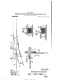
- Figure 1 is a diagrammatic view of a typical arrange ment of a main track and switch connections, showing my improved foot guard applied to the guard rails of the switch frog and between the switch points and track rails.
- Fig. 2 is a transverse section, taken on line 22 of Fig. 1.
- Fig. 3 is a fragmentary section of a typical crossing frog, showing two of the track rails of the crossing and their guard rails.
- Fig. 4k is a transverse section, taken on line li of Fig. 3.
- A, A designate the main rails of the track and B, B the rails of the switch or spur track.
- C, C designate switch points and D designates, as a whole, the switch frog, embracing the pointed or V-shaped fitting (Z at the meeting of the switch rail with the adjacent track rail, which fitting enters the space between the diverging ends 0 c of the switch point rails.
- E, E designate the usual guard rails placed one inside the outer rail of the switch track and the other inside the outer or far rail of the main track.
- F designates my improved foot guard located between the laterally turned ends of the guard rails E, E and the switch and main track rails, between the V-shaped fitting ⁇ Z of the frog and the laterally curved ends of the switch point rails, within the angle of said V-shaped frog fitting and also between the switch points and the track rails.
- the foot guards for the several locations mentioned, or others of like nature, are essentially the same, they beingjonly modified in cross-sectional contour and dimensions by reason of the different shape and size spaces between the rails occupied thereby.
- a typical cross-section of my improved foot guard is shown in Fig.
- the body of the foot guard completely fills the space between the webs of the adjacent rails A and E and vertically fills the spaces between the base flanges a, c and the heads a, e of said rails.
- the upper surface of the foot guard body may be provided with a groove to accommodate the flanges of the wheels which pass over the adjacent rails.
- G G designate two rails of a track which cross each other at right angles and H
- H designate the guard rails located at the intersection of the track rails G G
- the foot guards F F are located between the laterally curved ends of said guard rails II and the main track rails and are of substantially the same cross-sectional shape as the guard shown in Fig. 2.
- the said foot guards extend a distance inwardly from the outer or wider ends of the spaces to be guarded so as to close or fill said space up to a point where the space between the rails is so nar row as to preclude danger of the shoe of the person entering said space.
- foot guard which I have provided is exceedingly simple and inexpensive to install and that it requires no special attaching means to hold the same in place and does not require the piercing of the webs of the rails to receive such attaching means.
- the combination with the rails having parts which diverge from each other, of a body or mass of material laterally filling that portion of the space between the diverging portions of said rails in which the foot of a person is apt to wedge and vertically filling the space between the heads and base flanges of the rails, said material being of a nature to be applied in a plastic state and to subsequently set or harden in said space, the upper surface of the guard formed by such material being provided with a permanently open groove or recess to receive the flange of a wheel.
- FREDERICK IV RIZER. Vitnesses L. HALL, G. R. lVILKINS.
Landscapes
- Engineering & Computer Science (AREA)
- Architecture (AREA)
- Civil Engineering (AREA)
- Structural Engineering (AREA)
- Train Traffic Observation, Control, And Security (AREA)
Description
F. W. RIZER.
APPLICATION FILED FEB. 4, 1908,
Patented Aug. 3, 1909.
FOOT GUARD FOR RAILWAY SWITGHES AND CROSSING FROGS AND THE LIKE.
v five/21221 jFedejxc/i d jfijc-r W UNITED STATES PATENT OFFICE.
FREDERICK W. RIZER, OF CHICAGO, ILLINOIS, ASSIGNOR OF ONE-HALF TO F. M. PATTERSON, OF CHICAGO, ILLINOIS.
FOOT-GUARD FOR RAILWAY SWITCHES AND CROSSING-FROGS AND THE LIKE.
Specification of Letters Patent.
Patented Aug. 3, 1909.
' Application filed. February 4, 1908. Serial No. 414,195.
To all whom it may concern:
Be it known that I, FREDERICK IV. RIznR, a citizen of the United States, and a resident of Chicago, in the county of Cook and State of Illinois, have invented certain new and useful Improvements in Foot-Guards for Railway Switches and Crossing-Frogs and the Like; and I do hereby declare that the following is a full, clear, and exact description thereof, reference being had to the accompanying drawings, and to the letters of reference marked thereon, which form a part of this specification.
This invention relates to improvements in foot guards for railway switches, crossing frogs and like locations where there is liability of the shoe of a person being caught or wedged between two converging rails, and the invention consists in the matters hereinafter set forth and more particularly pointed out in the appended claims.
Among the objects of the invention is to provide a foot guard designed to afiord protection against the entrance of the foot of a person between two converging rails, as the guard rail of a switch or crossing frog, or between a main rail and a switch point rail, of such construction that the guard may be readily applied at the point requiring protection, thereby avoiding the necessity and expense of manufacturing the guard and thereafter fitting it to the guard or track rails as has heretofore been common.
A further object of the invention is to provide an improved foot guard for the purpose described which requires no specially devised attaching means for holding the same in place.
A. foot guard made in accordance with my invention comprises a mass or body of ma terial which is placed between the rails to be guarded while in a plastic state and which thereafter sets or hardens to form a solid body which closely conforms to the contour of the adjacent faces of the rail and vertically fills the spaces between the heads and base flanges of the rail, thereby affording an interlocking connection between the foot guard and the rails to prevent displacement of the guard. A material which I have found to be particularly well suited to the purpose of forming my improved foot guard is an asphaltum composition, on account of v the ease with which it may be handled. The
material from which the guard is made is applied at the point which requires protection after the rails have been laid and, by reason of the fact that the material may be poured into the space to be protected or guarded while in a plastic state, the said material vertically fills the space between the rails and head and base flanges ofthe rails and no additional or special attaching means is required to hold the same in place. Ordinarily the plastic material may be poured directly upon the base flanges between the rails and, if required, mold or form plates may be employed to limit the length of the guard body. If desired a base plate may be employed in which the guard body is molded.
I have shown in the drawings my improved foot guard applied to a switch and a crossing frog and to other points of the track requiring such protection.
As shown in the drawings :Figure 1 is a diagrammatic view of a typical arrange ment of a main track and switch connections, showing my improved foot guard applied to the guard rails of the switch frog and between the switch points and track rails. Fig. 2 is a transverse section, taken on line 22 of Fig. 1. Fig. 3 is a fragmentary section of a typical crossing frog, showing two of the track rails of the crossing and their guard rails. Fig. 4k is a transverse section, taken on line li of Fig. 3.
As shown in the drawings, A, A designate the main rails of the track and B, B the rails of the switch or spur track.
C, C designate switch points and D designates, as a whole, the switch frog, embracing the pointed or V-shaped fitting (Z at the meeting of the switch rail with the adjacent track rail, which fitting enters the space between the diverging ends 0 c of the switch point rails.
E, E designate the usual guard rails placed one inside the outer rail of the switch track and the other inside the outer or far rail of the main track.
F designates my improved foot guard located between the laterally turned ends of the guard rails E, E and the switch and main track rails, between the V-shaped fitting {Z of the frog and the laterally curved ends of the switch point rails, within the angle of said V-shaped frog fitting and also between the switch points and the track rails. The foot guards for the several locations mentioned, or others of like nature, are essentially the same, they beingjonly modified in cross-sectional contour and dimensions by reason of the different shape and size spaces between the rails occupied thereby. A typical cross-section of my improved foot guard is shown in Fig. 2, where in it will be seen that the body of the foot guard completely fills the space between the webs of the adjacent rails A and E and vertically fills the spaces between the base flanges a, c and the heads a, e of said rails. The upper surface of the foot guard body may be provided with a groove to accommodate the flanges of the wheels which pass over the adjacent rails.
In the construction shown in F 3, G G designate two rails of a track which cross each other at right angles and H, H designate the guard rails located at the intersection of the track rails G G The foot guards F F are located between the laterally curved ends of said guard rails II and the main track rails and are of substantially the same cross-sectional shape as the guard shown in Fig. 2. The said foot guards extend a distance inwardly from the outer or wider ends of the spaces to be guarded so as to close or fill said space up to a point where the space between the rails is so nar row as to preclude danger of the shoe of the person entering said space.
It will be apparent that the foot guard which I have provided is exceedingly simple and inexpensive to install and that it requires no special attaching means to hold the same in place and does not require the piercing of the webs of the rails to receive such attaching means.
I claim as my invention 1. In a railway track, the combination with the rails having parts which diverge from each other, of a body or mass of material laterally filling that portion of the space between the diverging portions of said rails in which the foot of a person is apt to wedge and vertically filling the space between the heads and base flanges of the rails, said material being of a nature to be applied in a plastic state and to subsequently set or harden in said space, the upper surface of the guard formed by such material being provided with a permanently open groove or recess to receive the flange of a wheel.
In a railway track, the combination with the rails of a track disposed at an angle to each other and guard rails located at the intersection thereof, of foot guards located between the laterally curved ends of the guard rails and the track rails and extendspaces between such rails to fill said spaces, said guards being formed of a normally plastic material introduced to fill the spaces and bear against the base and insides of the heads of the rails, the upper faces of the foot guard adjacent one of the rails being pro vided with a vertically normal open groove with one wheel in vertical alinement with the vertical wheel of the rail.
In testimony, that I claim the foregoing presence of two witnesses, this 31st day of January A; D. 1908.
FREDERICK IV. RIZER. Vitnesses L. HALL, G. R. lVILKINS.
as my invention I afiiX my signature in the ving inwardly from the outer ends of the
Priority Applications (1)
| Application Number | Priority Date | Filing Date | Title |
|---|---|---|---|
| US41419508A US929986A (en) | 1908-02-04 | 1908-02-04 | Foot-guard for railway switches and crossing-frogs and the like. |
Applications Claiming Priority (1)
| Application Number | Priority Date | Filing Date | Title |
|---|---|---|---|
| US41419508A US929986A (en) | 1908-02-04 | 1908-02-04 | Foot-guard for railway switches and crossing-frogs and the like. |
Publications (1)
| Publication Number | Publication Date |
|---|---|
| US929986A true US929986A (en) | 1909-08-03 |
Family
ID=2998410
Family Applications (1)
| Application Number | Title | Priority Date | Filing Date |
|---|---|---|---|
| US41419508A Expired - Lifetime US929986A (en) | 1908-02-04 | 1908-02-04 | Foot-guard for railway switches and crossing-frogs and the like. |
Country Status (1)
| Country | Link |
|---|---|
| US (1) | US929986A (en) |
-
1908
- 1908-02-04 US US41419508A patent/US929986A/en not_active Expired - Lifetime
Similar Documents
| Publication | Publication Date | Title |
|---|---|---|
| US1045741A (en) | Reinforced-concrete railway-tie. | |
| US1209477A (en) | Railroad-tie. | |
| US684106A (en) | Metallic railroad-tie. | |
| US1227345A (en) | Railroad-tie. | |
| US1021661A (en) | Railroad-tie and lock. | |
| US881984A (en) | Heel-block for railroad-frogs and the like. | |
| US990696A (en) | Railway-tie. | |
| US1233437A (en) | Railway-crossing. | |
| US1000498A (en) | Rail-support. | |
| US802450A (en) | Railway appliance. | |
| US938538A (en) | Railroad-tie. | |
| US998550A (en) | Concrete railway-tie. | |
| US868651A (en) | Insulated metal cross-tie. | |
| US912761A (en) | Metallic railway-tie and rail-fastener. | |
| US963758A (en) | Railway-crossing. | |
| US559284A (en) | Railroad-crossing | |
| US658541A (en) | Bond-tie electric railways. | |
| US985688A (en) | Rail joint and fastener. | |
| US976056A (en) | Railway-switch structure. | |
| US945906A (en) | Railway-tie. | |
| US1161217A (en) | Rail-joint. | |
| US1045645A (en) | Guard-rail clamp. | |
| US874556A (en) | Metal railway-tie. | |
| US964606A (en) | Compound rail. | |
| US898644A (en) | Movable-point crossing. |