US929187A - Control system for electric motors. - Google Patents
Control system for electric motors. Download PDFInfo
- Publication number
- US929187A US929187A US1907401271A US929187A US 929187 A US929187 A US 929187A US 1907401271 A US1907401271 A US 1907401271A US 929187 A US929187 A US 929187A
- Authority
- US
- United States
- Prior art keywords
- conductor
- switch
- circuit
- energy
- supplied
- Prior art date
- Legal status (The legal status is an assumption and is not a legal conclusion. Google has not performed a legal analysis and makes no representation as to the accuracy of the status listed.)
- Expired - Lifetime
Links
Images
Classifications
-
- H—ELECTRICITY
- H02—GENERATION; CONVERSION OR DISTRIBUTION OF ELECTRIC POWER
- H02J—ELECTRIC POWER NETWORKS; CIRCUIT ARRANGEMENTS OR SYSTEMS FOR SUPPLYING OR DISTRIBUTING ELECTRIC POWER; SYSTEMS FOR STORING ELECTRIC ENERGY
- H02J9/00—Circuit arrangements for emergency or stand-by power supply, e.g. for emergency lighting
- H02J9/04—Circuit arrangements for emergency or stand-by power supply, e.g. for emergency lighting in which the distribution system is disconnected from the normal source and connected to a standby source
- H02J9/06—Circuit arrangements for emergency or stand-by power supply, e.g. for emergency lighting in which the distribution system is disconnected from the normal source and connected to a standby source with automatic change-over, e.g. UPS systems
- H02J9/062—Circuit arrangements for emergency or stand-by power supply, e.g. for emergency lighting in which the distribution system is disconnected from the normal source and connected to a standby source with automatic change-over, e.g. UPS systems for AC powered loads
Definitions
- My invention relates to systems of electric motor control, and has speclal reference to I the control of electric vehicle motors which low voltages, the operatingelectro-magnets are adapted to receive energy from either direct or al'ternatlng current sources.
- the object of my invention is'to'providc' a system of the classabove indicated that shall .be simple in arrangement and effective in operation and that shall embody secondary batteries forenergizing the control circuits of the system and automatic means for adapting the main source of supply by convers1on or voltage. reduction, according as alternating or direct current is supplied to the motors, for charging the secondary batteries.
- storage batteries are ordidirect currcnts 'narily employect'for supplying energy to the control circuits in order that the operating magnets may be constructed for low voltages.
- I provide a well known means for convertingalternating'current to direct current, such as'a motor-generator set or a rotary concurrent main line potential tor, charging purmain circuits of motor control other means for. adapting; the direct"
- 'a plurality and afield magnet windings 5, [6, 7, and 8 maybe supplied with energy from 'direct or alternating current sources, through trolley conductors 9 and 10 andtrolleys 11 and rail conductor 13.
- the direct current trolley 11 is controlled manually, but the alternating current trolley 12 which is of the panto graph type, comprises "a' contact shoe 14, a spring 15 which normally holds the .shde in engagement with the trolley conductor, lowering pistons cylinder 18, and a latch 19, and is governed by 'electro-magnctically actuated valves '20 and 21.
- f' Alternating current energy issupplied directly from the trolley"12 through con-j ductor 22, line swit'ch 23, magnet winding 24-.o fa relay switch 25 and conductor 26 to one .terminal" of .a transformer 27, the op- .posjiteifterminal "of-the transformer being connected to conductor 28.
- y Energy is supplied'from'the direct current trolley 11 through a conductor 29, switch. 30, conductor 31 and line switch 32 to one terminal of a resistance comprising sections 33, 34, 35, and 36-.
- Motors 1 and 2 may be permanently connected together electrically and the motors 3 and 4 may be similarly connected so that motor and the circuit connections of. the. groups may be 'v'aried from ,a series: to a parallel relation and may, be connected to, or disconnected from, a line by a plurality of independently-operated switchesifi'l; -38,
- the amount-of resistance included in the circuit may be varied by a series of switches 41,42, 4 3,' 'and 44' and the alternating cur rent voltage applied to the motors is govof electric motors having armatures 1, 2, 3,
- the circuit being completed through a 16 and -17 that operate inathe rail conductor 13 by a each group may be considered as a single erned by a group of independently-operated are similar to each other, so that one may be connected at all times to the control circuit of" the system while the other is connected to a charging circuit, the circuit connections being governed by a four -'pole double-throw switch 60.
- the charging e11- cuit is supplied with energy either from a motor-generator set, comprising an1alternating current motor 130 and a direct current generator 131, or from the direct current supply circuit 9, connections being established, as hereinafter set forth, through fa'j ".relay switch 132 and a varia l "'ance "133.
- switch 60 As soon as switch 60 is closed, a control circuit is established from the storage battery59 through conductor 134, switch blade 135 of switch 60 conductor 136, switch 60, conductor 61, magnet winding 62, conduct0r65, negative conductor 66, switch blade 137 and conductor 138 to the negative terminal of the battery.
- the magnet winding 62 when energized, releases a latch 63, which is operated by a spring 64, and effects the closure of the switch 25, which completes a control circuit from'the battery through a switch 67, a con ductor 68, an operating magnet winding 69 of the line switcn 23, switch 25 and conductor to the negative conductor 66.
- the alternating current circuit being normadly-made and interrupted by the engagement or disengagement of the trolley with or from. the supply line conductor.
- the transformer 27 is energized, as above indicated, current is supplied from a low-voltage tap 70 through a conductor 71 to a magnet winding 72, from which point the circuit is completed through conductors 73 and 28 to return circuit conductor 13. .lVhen energized, the magnet winding 72 raises the switch 57, and a circuit is then completed from conductor 136 through a switch 74, conductor 75, contact fingers 76 of the switch 57, contactmembers 77 (which are bridged by the contact member 78 of the switch 56) and conductor 79 to magnet winding 55 of the change-over switch 53, circuit being comleted from this point through the negative conductor66.
- the change-over switch 53 is moved to occupy position x by the magnet winding 55, when'energized, in order that the motors may be supplied with alternating current energy.
- the contact member 82 is engaged by a contact finger 9land energy is supplied from this finger through conductor 92, contact fingers 93, and conductor 94 to the magnet winding of the'switch 52, the circuit being completed, as before, through the negative conductor 66.
- switches 48, 51, 47, 50, 46, 49, and 45 are i "so 52 permittedto open, and, asthe switch 46 1's closed, the swltch 18 opens, and so on,
- the valve 20 closes an exhaust port 113
- the contact shoe 14 is provided with a spring catch .116, as shown in Fig. drawings, that engages a hook projection 11.7 on'the latch 19.
- the same lowering action of the trolley may be effected auton'iatically when the trolley circuit is interrupted by the separation of the car wheels from the rails, in case of accident, or by the normal passing of the trolley shoe onto a dead section for the purpose of changing from nlternating to direct current operation.
- the magnet winding 1 13 when energized, closes relay switch 132 whereupon a circuit is completed from conductor '142, through magnet windin 14:3, switch 132, conductors 147 and 148, switch blade 149,-and conductor 150,'to one terminal of the battery "59, the
- the motor 130 when energized, drivesthe direct current generator deliver energy from a positive commutator brush 155 through conductor 156'and a blade 157 of a switnh 158, conductor 147, SWltCh 131, which will then blade 14:9 and conductor 150 to one terminal of the battery 59, as above indicated.
- Ihe opposite commutator brush 159 is connected by conductor 160, the other blade of switch 158, conductor 152, switch blade 151 and conductor 150 to form a battery charging circuit.
- the battery 59 is thus charged with suitable-energy, provided the direct current generator is properly designed and propelled, irrespective of the kind of energy supplied to the main circuits of the system.
- a control system for electricyehicles the combination with alternating and direct current supply circuits, electric propelling motors, secondary batteries and motor control circuits supplied therefrom, of a motor generator set for adapting the energy received from the alternating current source for charging the battery, a change-over switch for effecting the 'propercontrol circuit connections for motor operation by alternating or direct currents, and a relay switch dependent upon 'the position of the change-over switch for automatically supplying direct current energy for charging the battery..1
- change-over switch for connecting the motors to one or the other of the circuits, and operating electro-magnets for the changeover'switch, of secondary batteries to energize the magnets, and means dependent upon the position of the change-over switch for automatically supplying suitable current to the batteries.
Landscapes
- Business, Economics & Management (AREA)
- Emergency Management (AREA)
- Engineering & Computer Science (AREA)
- Power Engineering (AREA)
- Control Of Multiple Motors (AREA)
Description
H. L. BEACH. CONTROL SYSTEM FOR ELECTRIC MOTORS.
APPLICATION FILED NOV. 8, 1907.
929, 187, Patented July 27, 1909.
WITNESSES:
INVENTOR ATTORNEY UNITED STATES PATENT OFFICE.
HOWARD L. BEACH, OF WILKINSBURG, PENNSYLVANIA, ASSIGNOR, BYMESNE ASSIGNMENTS, TO WESTINGHOUSE ELECTRIC & MANUFACTURING COMPANY, OF EAST PITTSBURG, PENNSYLVANIA, A CORPORATION OF PENNSYLVANIA.
con'rnor. sys'rmr FOR ELECTRIC Morons.
specification of Letters Patent. Patented iluly 27, 1909.,
Apialication filed November 8, 1907. Serial No. 401,271.
To ally/ham it may concern: I Be it known that I, IIOWARDL. BEACH, a
citizen of the United States, and a resident lowing is a specification.
My invention relates to systems of electric motor control, and has speclal reference to I the control of electric vehicle motors which low voltages, the operatingelectro-magnets are adapted to receive energy from either direct or al'ternatlng current sources.
The object of my invention is'to'providc' a system of the classabove indicated that shall .be simple in arrangement and effective in operation and that shall embody secondary batteries forenergizing the control circuits of the system and automatic means for adapting the main source of supply by convers1on or voltage. reduction, according as alternating or direct current is supplied to the motors, for charging the secondary batteries.
llhe'n 'the systems are supplied with energy from alternating current sources, the control circuits areoften supplied with currents at relatively for the control switches being specially adapted for thiskind of energy. It, howthe main circuits are supplied with ever,
storage batteries are ordidirect currcnts 'narily employect'for supplying energy to the control circuits in order that the operating magnets may be constructed for low voltages.
The latter arrangement has also beenused when the main circuits of the system are supplied from either direct or alternating current sources, the storage batteries being "charged from direct current sources only.
! plied with energy from direct or from alter In electric railroads where sections of materlal length are equipped with alternating current trolley conductors, it becomes desirable to provide suitable me'ans-tor charging the batteries, whether. the motors are sup- --nating current sources.
. verter,
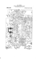
According to my present invention, I provide a well known means for convertingalternating'current to direct current, such as'a motor-generator set or a rotary concurrent main line potential tor, charging purmain circuits of motor control other means for. adapting; the direct" Referring to the drawings, 'a plurality and afield magnet windings 5, [6, 7, and 8 maybe supplied with energy from 'direct or alternating current sources, through trolley conductors 9 and 10 andtrolleys 11 and rail conductor 13. The direct current trolley 11 is controlled manually, but the alternating current trolley 12 which is of the panto graph type, comprises "a' contact shoe 14, a spring 15 which normally holds the .shde in engagement with the trolley conductor, lowering pistons cylinder 18, and a latch 19, and is governed by 'electro-magnctically actuated valves '20 and 21. f' Alternating current energy issupplied directly from the trolley"12 through con-j ductor 22, line swit'ch 23, magnet winding 24-.o fa relay switch 25 and conductor 26 to one .terminal" of .a transformer 27, the op- .posjiteifterminal "of-the transformer being connected to conductor 28. y Energy is supplied'from'the direct current trolley 11 through a conductor 29, switch. 30, conductor 31 and line switch 32 to one terminal of a resistance comprising sections 33, 34, 35, and 36-. v
Motors 1 and 2 may be permanently connected together electrically and the motors 3 and 4 may be similarly connected so that motor and the circuit connections of. the. groups may be 'v'aried from ,a series: to a parallel relation and may, be connected to, or disconnected from, a line by a plurality of independently-operated switchesifi'l; -38,
39, and 40'.
The amount-of resistance included in the circuit may be varied by a series of switches 41,42, 4 3,' 'and 44' and the alternating cur rent voltage applied to the motors is govof electric motors having armatures 1, 2, 3,
12'. the circuit being completed through a 16 and -17 that operate inathe rail conductor 13 by a each group may be considered as a single erned by a group of independently-operated are similar to each other, so that one may be connected at all times to the control circuit of" the system while the other is connected to a charging circuit, the circuit connections being governed by a four -'pole double-throw switch 60. The charging e11- cuit is supplied with energy either from a motor-generator set, comprising an1alternating current motor 130 and a direct current generator 131, or from the direct current supply circuit 9, connections being established, as hereinafter set forth, through fa'j ".relay switch 132 and a varia l "'ance "133.
The operation of, and the circuit connections for, the system are as follows: Assuming that the alternating current trolley 12 engages its supply conductor 10, and that the various switches of the system occupy the positions shown in the drawing, line switches 23 and 32 being open, the motors may be accelerated by first closing'a re-set switch 60 and by moving the master controller 58 to occupy positions a, b, c, d, e, f, g, and h, successively. As soon as switch 60 is closed, a control circuit is established from the storage battery59 through conductor 134, switch blade 135 of switch 60 conductor 136, switch 60, conductor 61, magnet winding 62, conduct0r65, negative conductor 66, switch blade 137 and conductor 138 to the negative terminal of the battery. The magnet winding 62, when energized, releases a latch 63, which is operated by a spring 64, and effects the closure of the switch 25, which completes a control circuit from'the battery through a switch 67, a con ductor 68, an operating magnet winding 69 of the line switcn 23, switch 25 and conductor to the negative conductor 66. As soon as the line switch 23 is closed by the energized magnet winding 69, a main circuit is established from, alternating current supply conductor 10 through the trolley 12 conductor 22, line switch 23, overload release coil 2-4 of the switch 25 and conductor 26 to one terminal of the, autotransformer 27, the opposite terminal of the transformer being connected to the ra1l conductor 13 by a conductor 2-8. The holding circuit of the lineswitch 23 is maintained t-hrough'the switch 25,except under overload conditions,
the alternating current circuit being normadly-made and interrupted by the engagement or disengagement of the trolley with or from. the supply line conductor.
lVhen the transformer 27 is energized, as above indicated, current is supplied from a low-voltage tap 70 through a conductor 71 to a magnet winding 72, from which point the circuit is completed through conductors 73 and 28 to return circuit conductor 13. .lVhen energized, the magnet winding 72 raises the switch 57, and a circuit is then completed from conductor 136 through a switch 74, conductor 75, contact fingers 76 of the switch 57, contactmembers 77 (which are bridged by the contact member 78 of the switch 56) and conductor 79 to magnet winding 55 of the change-over switch 53, circuit being comleted from this point through the negative conductor66. The change-over switch 53 is moved to occupy position x by the magnet winding 55, when'energized, in order that the motors may be supplied with alternating current energy.
If the master controller 58 is moved to occupy position a, energy is supplied from conductor 136 through contact finger 80 to contact members 81 and 82, a circuit being continued from contact finger 81 through contact finger 83, conductor 84, and conductor 85 to the magnet winding of the switch 38, the opposite terminal of this winding being connected to negative conducto1 66. A second circuit is established from the conductor 84, through contact fingers 86 (that "are bridged by a contact member 87 when the change-over switch 53 occupies position :0), to conductor 88, the circuit beingdivided from this point so that energy is supplied through conductors 89iand 90 to the magnet windings-of switches 37 and 39.
The contact member 82 is engaged by a contact finger 9land energy is supplied from this finger through conductor 92, contact fingers 93, and conductor 94 to the magnet winding of the'switch 52, the circuit being completed, as before, through the negative conductor 66. In this way, the switches 38, 3 9, 37, and 52 are closed and alternating current energy is supplied from a low-voltage tap 95 of the'transfor ner 27, through switch '52, conductor 96, preventive coils 97 and 93,-and conductor-99 to the switches 38 and 39, two branch circuits being completed from this point to the negative rail conductor 13, one of them being established through switch 38, field magnet windings 6 and 5, motor armatures 2 and 1 and switch 37, and the other being established through switch 39, field magnet windings 8 and 7 and motor armatures4and 3.
If the master controller is" movedvto successively" occupy positions 12,0, cl, c,f, g, and it, switches 48, 51, 47, 50, 46, 49, and 45 are i "so 52 permittedto open, and, asthe switch 46 1's closed, the swltch 18 opens, and so on,
four, of the switches being closed at one time. The voltage variations are accomplished, without atany time interrupting the circuit or directly short-circuiting any of the transformer turns, by the use of three preventive coils, 97,98, and 107 which are manipulated as illustrated and described in Patent No. 834,525, granted October .30, 1906, to the \Vestinghouse Electric & Manufacturing Company, as assi 'nee of Ray P. Jackson.
'itgis desired to render the apparatus on the vehicle electrically dead, the switch.
(st-maybe moved temporarily, in opposition ton-spring 108, into contact with awfinger 109, thereby interrupting the circuit which was formeriy established through the magnet winding 69 of the line switch 23. The magnet winding 72 being deenergized, be- .cause energy is cut ofi from the transformer, switch 57. drops to its lower position circuit isthen established from a cond ctor 75 through contact fingers 110 and conductor 111 to magnet winding 112 of the magnet valve 20. I
The valve 20 closes an exhaust port 113,
" when its magnet is energized, and thus ad- @fbcing completed through 'lhe windmg 119 being thus mits fluid-pressure from a storage reservoir 114 through a pipe 115 to cylinder 18 between the pistons 16 and 17, which are immediately. separated, thereby lowering the contact shoe 14, in opposition to the spring 15.
The contact shoe 14: is provided with a spring catch .116, as shown in Fig. drawings, that engages a hook projection 11.7 on'the latch 19. The same lowering action of the trolleymay be effected auton'iatically when the trolley circuit is interrupted by the separation of the car wheels from the rails, in case of accident, or by the normal passing of the trolley shoe onto a dead section for the purpose of changing from nlternating to direct current operation.
Assuming that the alternating current trolley 12 is lowered and that the master controllerfiS is in its off position, it' the direct current trolley 11 now moved into engagement with a direct current supply conductor 9, energy is first supplied through a conductor 29 and switch 30 to magnet winding 119 of the relay switch 56, a circuit the track rail 13. energized, the
relav swltch 1s raised and a control circuit is completed from further 2 of the the conductor 136,
through switch 74, conductor 75,. contact fingers 110 of the switch 57, contact fingers 120 (that are engaged by .contact number 18) and conductor 121 to operating magnet ot' the change-over switch 53, which is then moved to position u -it the master controller is again moved to occupy positions a to 1'1, inclusive, the motors'may be supplied with energy from the direct current source, the resistance 33, which isv at first included in the circuit, being gradually; reduced, as the motor is accelerated. The operation of this portion of the system, together with that of the complete system, in changing from direct current to alternating current, or=vice verse, is clearly set forth in detail in my co-pending application, Serial No. 391,746, filed September 26, 1907,: consequently, I deem it unnecessary to include a description of the same herein.
It the switch-GOoccupies the position indicated in the drawing and the change over switch 53 occupies position y, so that direct current may be supplied to the system, energy is supplied from the conductor 9 through conductor 29, switch 30, conductor 31, conductor 39, contact'fingers 1 10 (which are bridged by contact member 14:1 when the change-over switch I occupies the position y), conductor 1 12, magnet winding 113 of relay switch 132, movable contact arm 1 1 1 of resistance 133 and conductor 145, conductor 146, and conductors 73 and 28 to the negative rail conductor 13.
The magnet winding 1 13, when energized, closes relay switch 132 whereupon a circuit is completed from conductor '142, through magnet windin 14:3, switch 132, conductors 147 and 148, switch blade 149,-and conductor 150,'to one terminal of the battery "59, the
other terminal of the battery being con-- nected through conductor 150 switch blade 151, and conductor 152-to conductor, 1 16,
from which point a circuit is completed to '110 dicated. Thus, the line Voltage-reducedby the negative rail conductor 13, as above inthe resistance of magnet winding M3,:which may be made of any suitablevalue, is applied to the battery '59, which is charged"- accordingly. v
If the. change-over sition 00, indicating that the motor circuits are supplied with energy from the alternating current circuit '10. and that the transformer 27 is energized, current is supplied from an intermediate tap 153 of the transformer, through conductor 154: .to .the motor 130, the opposite terminal of the motor being switch 53 occupies poconnected toxthe negative'rail conductor 13 through conductor 146, as above indicated.
The motor 130, when energized, drivesthe direct current generator deliver energy from a positive commutator brush 155 through conductor 156'and a blade 157 of a switnh 158, conductor 147, SWltCh 131, which will then blade 14:9 and conductor 150 to one terminal of the battery 59, as above indicated. Ihe opposite commutator brush 159 is connected by conductor 160, the other blade of switch 158, conductor 152, switch blade 151 and conductor 150 to form a battery charging circuit. The battery 59 is thus charged with suitable-energy, provided the direct current generator is properly designed and propelled, irrespective of the kind of energy supplied to the main circuits of the system.
lVhen the position of thefour-pole double- -throw switch 60 is reversed, the battery 59 be imposed as are indicated in the appended claims.
I claim as my invention: j
1. In a control system, the combination with a pluralityof motors, control switches therefor, operating magnets for the switches,
and secondary batteries to energize the magnets, of a plurality of means for charging the batteries from unlike sources of energy, and automatic means for selecting one of. said means.
2. In -a control system, the combination with dissimilar supply circuits, electric mo tors adapted to 'receive energy from either circuit, control switches therefor, operating magnets for the switches, and secondary batteries for energizing the magnets, of a plurality of means for adapting the energy of the supply circuits for charging the batteries, and automatic means dependent upon the energy supplied to the motors for selectingthe suitable adapting means.
3. In a control system, the combination with alternating and direct current supply circuits, electric motors adapted to receive energy from either supply circuit, electrically governed control switches for determining the speed and direction of rotation of the motors, and secondary batteries for energizing the control circuits, of a plurality of means for adapting the' supply circuit energies for charging the batteries, and selective means, dependent upon the kind of energy supplied to the motors, for automatically supplying suitable current'to the batterles 4. In a control system, the combination with electric motors, supply circuits and control circuits therefor, secondary batteries for the control circuits, and a charging circuit for the batteries, of dynamo-electric mechply circuit to the charging circuit when energy is supplied therefrom to the motors.
5. In a control system for electric vehicles,
the combination with electric propelling motors, alternatingand direct current supply circuits therefor, motor control circuits and secondary batteries therefor, a charging circuit for the batteries, and a switching device for connecting one of the batteries to the control circuits and the other to the charging circuit, of means for adapting the energy recelved from the alternating current source for charging the battery, and other means for adapting the direct current source for charging the battery, and automatic means for selecting one of the adapting means, according as alternating or direct current energy is supplied to the motors.
6. In a control system for electricyehicles, the combination with alternating and direct current supply circuits, electric propelling motors, secondary batteries and motor control circuits supplied therefrom, of a motor generator set for adapting the energy received from the alternating current source for charging the battery, a change-over switch for effecting the 'propercontrol circuit connections for motor operation by alternating or direct currents, and a relay switch dependent upon 'the position of the change-over switch for automatically supplying direct current energy for charging the battery..1
- 7. In a control system, the comblnation with dissimilar'supply circuits, electric motors adapted to be operated therefrom, a'
change-over switch for connecting the motors to one or the other of the circuits, and operating electro-magnets for the changeover'switch, of secondary batteries to energize the magnets, and means dependent upon the position of the change-over switch for automatically supplying suitable current to the batteries.
8. In a control system, the combination with alternating and direct current supply circuits, electricmotors capable of'being operated from either source and a change-over switch for governing the motor connections, of actuating electro-magnets for the changeover switch, secondary batteries for energize ing the electro-magnets, and means dependentupon the position of the change -over switch for automatically supplying suitable current to the batteries.
In testimony whereof, I have hereunto subscribed my name this 30th day of Oct., 1907.
HQIVARD L. BEACH. 'itnesses:
lViLLLur Coornn,
BIRNEY HINES.
Priority Applications (1)
| Application Number | Priority Date | Filing Date | Title |
|---|---|---|---|
| US1907401271 US929187A (en) | 1907-11-08 | 1907-11-08 | Control system for electric motors. |
Applications Claiming Priority (1)
| Application Number | Priority Date | Filing Date | Title |
|---|---|---|---|
| US1907401271 US929187A (en) | 1907-11-08 | 1907-11-08 | Control system for electric motors. |
Publications (1)
| Publication Number | Publication Date |
|---|---|
| US929187A true US929187A (en) | 1909-07-27 |
Family
ID=2997612
Family Applications (1)
| Application Number | Title | Priority Date | Filing Date |
|---|---|---|---|
| US1907401271 Expired - Lifetime US929187A (en) | 1907-11-08 | 1907-11-08 | Control system for electric motors. |
Country Status (1)
| Country | Link |
|---|---|
| US (1) | US929187A (en) |
-
1907
- 1907-11-08 US US1907401271 patent/US929187A/en not_active Expired - Lifetime
Similar Documents
| Publication | Publication Date | Title |
|---|---|---|
| US3564342A (en) | Motor control system | |
| US1506754A (en) | Motor-control system | |
| US967387A (en) | System of control for alternating-direct-current motors. | |
| US665143A (en) | Control of electric motors. | |
| USRE13115E (en) | goopee | |
| US874869A (en) | Control system for electric vehicles. | |
| US1112439A (en) | Electric-circuit-control system. | |
| US1529762A (en) | Control system | |
| US869824A (en) | Control system. | |
| US1389150A (en) | System of control | |
| US806709A (en) | Switch-operating mechanism. | |
| US2206706A (en) | Control system | |
| US874558A (en) | Alternating-direct-current system of control. | |
| US735170A (en) | Electromagnetic switch for electric railways. | |
| US1519284A (en) | Motor-control system | |
| US1248484A (en) | System of distribution. | |
| US2241961A (en) | Control system | |
| US1824846A (en) | Control system | |
| US1308229A (en) | Edward i | |
| US868911A (en) | Electric-railway system. | |
| US1204432A (en) | Control system for electric motors. | |
| US1189292A (en) | Control system. | |
| US870147A (en) | Multiple-unit-controlling system for electric locomotives or motor-cars. | |
| US1435262A (en) | System of control | |
| US1233402A (en) | Control system. |