US9287693B2 - Enhanced strength grade level utilities enclosure - Google Patents
Enhanced strength grade level utilities enclosure Download PDFInfo
- Publication number
- US9287693B2 US9287693B2 US13/830,670 US201313830670A US9287693B2 US 9287693 B2 US9287693 B2 US 9287693B2 US 201313830670 A US201313830670 A US 201313830670A US 9287693 B2 US9287693 B2 US 9287693B2
- Authority
- US
- United States
- Prior art keywords
- enclosure
- vertical
- wall structure
- wall
- load
- Prior art date
- Legal status (The legal status is an assumption and is not a legal conclusion. Google has not performed a legal analysis and makes no representation as to the accuracy of the status listed.)
- Active, expires
Links
Images


Classifications
-
- H—ELECTRICITY
- H02—GENERATION; CONVERSION OR DISTRIBUTION OF ELECTRIC POWER
- H02G—INSTALLATION OF ELECTRIC CABLES OR LINES, OR OF COMBINED OPTICAL AND ELECTRIC CABLES OR LINES
- H02G9/00—Installations of electric cables or lines in or on the ground or water
- H02G9/10—Installations of electric cables or lines in or on the ground or water in cable chambers, e.g. in manhole or in handhole
-
- G02B6/4451—
-
- G—PHYSICS
- G02—OPTICS
- G02B—OPTICAL ELEMENTS, SYSTEMS OR APPARATUS
- G02B6/00—Light guides; Structural details of arrangements comprising light guides and other optical elements, e.g. couplings
- G02B6/46—Processes or apparatus adapted for installing or repairing optical fibres or optical cables
- G02B6/50—Underground or underwater installation; Installation through tubing, conduits or ducts
- G02B6/501—Underground or underwater installation; Installation through tubing, conduits or ducts underground installation of connection boxes
-
- H—ELECTRICITY
- H02—GENERATION; CONVERSION OR DISTRIBUTION OF ELECTRIC POWER
- H02G—INSTALLATION OF ELECTRIC CABLES OR LINES, OR OF COMBINED OPTICAL AND ELECTRIC CABLES OR LINES
- H02G3/00—Installations of electric cables or lines or protective tubing therefor in or on buildings, equivalent structures or vehicles
- H02G3/02—Details
- H02G3/08—Distribution boxes; Connection or junction boxes
- H02G3/18—Distribution boxes; Connection or junction boxes providing line outlets
- H02G3/185—Floor outlets and access cups
-
- G—PHYSICS
- G02—OPTICS
- G02B—OPTICAL ELEMENTS, SYSTEMS OR APPARATUS
- G02B6/00—Light guides; Structural details of arrangements comprising light guides and other optical elements, e.g. couplings
- G02B6/44—Mechanical structures for providing tensile strength and external protection for fibres, e.g. optical transmission cables
- G02B6/4439—Auxiliary devices
- G02B6/444—Systems or boxes with surplus lengths
- G02B6/4441—Boxes
- G02B6/4442—Cap coupling boxes
- G02B6/4444—Seals
Definitions
- This invention relates to enclosures for underground utility lines, and more particularly, to an underground utility enclosure having improved load capacity.
- Underground utility equipment enclosures include the so-called grade level vaults, splice boxes, pull boxes, and the like, for various applications requiring access to an underground service. These may include electrical, gas, water, telephone, fiber optics and cable TV installations, for example.
- Grade level enclosures are commonly subjected to different kinds of structural loads during use.
- prior art enclosures and their cover plates are made from reinforced concrete, fiberglass, or polymer concrete composite materials for added load strength, to withstand the compression forces during use.
- Grade level enclosures are adapted to facilitate use with different types of internal equipment. They may include splice cases, fiber optic cables, electrical wires, and the like, supported in the enclosure by metal cable racks fastened to upper portions of the enclosure's inside walls.
- the ANSI/SCTE 77-2010 performance specification includes a three-position structural test simulating wheels rolling over an enclosure where loads are imparted laterally and vertically onto the side wall of the enclosure and vertically onto its cover.
- the related structural integrity tests comprise:
- Position three a cover test—a test showing how an enclosure responds to a load applied directly to the center of the cover.
- the present invention provides an enhanced strength grade level utilities enclosure that can be made from lighter weight polymeric materials.
- the enclosure's design provides enhanced structural loading capacity in excess of ANSI Tier 15 vertical side wall load and center cover vertical load requirements.
- the ANSI Tier 15 test standards are one example of various industry test standards for grade level enclosures for which the present invention provides enhanced load capacities. Structural improvements, in particular, are demonstrated for enclosures' vertical side wall load capacities; and these improvements would result for different types of enclosures each having their own separate vertical side wall load capacity requirements.
- one embodiment of this invention comprises an enhanced strength grade level utility enclosure which includes a vertical wall structure made of a molded polymeric material.
- the vertical wall structure has an upright inner wall extending from the upper edge to the bottom of the vertical wall structure.
- the inner wall faces the interior of the enclosure.
- One or more narrow, vertically extending slotted regions are recessed in the inside face of the inner wall.
- Upright rigid support bars adapted for use as cable racks, are positioned in separate slotted regions formed on the inside face of the wall structure.
- the support bars provide a substantially continuous means of rigid vertical load support extending from the upper edge down to the bottom edge of the enclosure's vertical wall structure.
- the recessed support bars in combination with the vertical wall structure provide enhanced wall load strength sufficient for exceeding vertical side wall load test standards, among other test standards, for grade level enclosures.
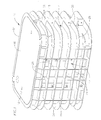
- FIG. 1 is a perspective view showing one embodiment of an enhanced strength grade level utilities enclosure according to principles of this invention.
- FIG. 1A is a perspective view showing another embodiment of the utilities enclosure.
- FIG. 2 is an enlarged fragmentary perspective view showing the construction of a prior art grade level utilities enclosure.
- FIG. 3 is an enlarged fragmentary perspective view showing the detailed construction of the enhanced strength grade level utilities enclosure according to principles of this invention.
- FIG. 4 is a front elevational view, partly in cross section, showing an inside wall of the enhanced strength enclosure.
- FIG. 5 is a cross sectional view taken on line 5 - 5 of FIG. 4 .
- FIG. 6 is a cross sectional view taken on line 6 - 6 of FIG. 4
- FIG. 7 is a schematic perspective view showing a test set up for a side wall load test according to ANSI/SCTE 77-2010 Tier 15.
- FIG. 8 is a schematic perspective view showing a test set up for a Tier 15 center load test.
- FIG. 9 shows comparative deflection curves for tests conducted on the present invention.
- FIG. 10 shows comparative deflection curves for tests conducted on a modified utilities enclosure.
- FIG. 11 shows comparative deflection curves for tests conducted on a prior art utilities enclosure.
- FIG. 1 illustrates one embodiment of a grade level underground utilities enclosure 10 according to principles of this invention.
- the enclosure includes a pair of long parallel side walls 12 and a pair of shorter endwalls 14 forming a generally rectangular structure having a hollow interior.
- the grade level enclosure has an open bottom.
- An open top of the enclosure receives a flat top cover plate or panel 16 .
- the enclosure is made of hard molded plastic such as high density polyethylene and is molded in halves, split along its longitudinal center axis into two parts, forming a seam 18 at each end. The two halves are rigidly fastened together along the seams at each end by fasteners at 20 extending through upright flanges 22 which face each other along each seam.
- the enclosure also has a molded integrally formed grid structure facing outwardly along each side wall.
- the configuration of the grid structure can be in various forms.
- the illustrated grid structure has an I-beam configuration formed by long horizontal flanges 24 and vertical upright flanges 26 , forming an essentially rectangular array.
- the horizontal flanges wrap around the ends of the enclosure at 28 .
- This construction of the enclosure provides good compressive strength to resist vertical loads on the side walls of the enclosure.
- Other configurations can include diagonally extending or diamond pattern molded flanges, for example.
- FIG. 1A shows the same embodiment, with a top cover plate 30 opened to reveal the interior of the enclosure, described in more detail below.
- This embodiment also illustrates use of a polymer composite ring 32 positioned on a top edge of the enclosure's vertical side wall structure.
- the cover plate 30 rests on the polymer composite ring during use.
- This embodiment also illustrates use of the cover plate 30 made of a polymer concrete material.
- the body of the enclosure is made from a non-metal, non-concrete, molded thermoplastic polymeric material such as high density polyethylene. Other thermoplastic materials comprised of polyolefin materials in general also can be used.
- FIGS. 2 and 3 illustrate a comparison between the present invention ( FIG. 3 ) and a prior art grade level utilities enclosure ( FIG. 2 ).
- FIG. 2 illustration shows the prior art enclosure 34 having a vertical wall structure with a flat inside vertical wall surface 35 .
- This embodiment shows narrow elongated recessed slots 36 extending parallel to the top edge of the box. These slots are formed below an inside peripheral rim 38 which extends around and somewhat below a top edge 39 of the enclosure. The slots can be used for interlocking with a cover plate locking device when a cover plate is positioned atop the enclosure.
- This prior art embodiment also shows a typical prior art use of a narrow, elongated metal cable rack 40 affixed to the flat inside wall surface 35 of the enclosure.
- the cable rack as is well known in the art, includes a series of vertically spaced apart stepped connectors 42 for use in attaching various types of equipment used in the interior of the enclosure.
- the top and bottom of the cable rack are affixed to the side wall of the enclosure by suitable fasteners 44 .
- the enclosure of this invention includes two cable racks 60 on each side, described below, and a hanger bar 33 that provides an organizer feature for internal equipment.
- the hanger bar is attached to the enclosure at its ends without fasteners.
- FIG. 3 illustrates a more detailed construction of the underground enclosure 10 which is open at its top and reveals the interior of the enclosure.
- the vertical wall structure of the enclosure is formed by having integrally molded a vertical inner wall panel 46 with the exterior grid structure (formed by the horizontal and vertical flanges 24 and 26 ).
- the vertical inner wall has a flat inside surface 48 that extends continuously around and faces toward the open interior of the enclosure.
- FIG. 3 illustration also shows a narrow horizontal annular rim 50 that extends around the upper inside portion of the enclosure.
- the rim extends inwardly around and below a short vertical wall 52 that spans an upper portion of the enclosure.
- An annular outer flange 54 above the shortened wall 52 forms the top edge of the enclosure.
- the vertical wall structure's load strength is enhanced by a system of substantially vertically extending rigid support bars inserted into corresponding narrow, elongated recessed regions or pockets 58 molded into the otherwise flat inside surface 48 of the vertical inside wall panel 46 .
- the rigid support bars are preferably formed as cable racks 60 adapted for supporting various types of internal equipment used in the enclosure, via a stepped series of vertically spaced apart connectors 61 on the base of each cable rack.
- Each cable rack is generally U-shaped or channel-shaped in cross sectional configuration, having a flat base 62 flush with the enclosure's inside surface 48 when the bar is positioned in the recessed slotted region.
- the side walls of the channel-shaped cable racks rigidly engage the bottoms of the recessed pockets 58 in which they are positioned.
- the cable rack is rigidly affixed to the recessed regions by a series of vertically spaced apart fasteners 64 (and corresponding threaded nuts and washers) screwed into corresponding holes 66 in the wall of the enclosure.
- the cable racks are preferably made from galvanized steel or stainless steel, although they can be made from hard plastic or fiberglass. In one embodiment the metal cable racks have a depth of about 9/16 inch, a width of about 11 ⁇ 2 inches, and a thickness of about 1 ⁇ 8 inch.
- FIGS. 4 to 6 illustrate in more detail the structural configuration of the enhanced strength enclosure provided by the invention.
- two cable racks 60 are positioned on each longitudinal side wall of the enclosure, although more cable racks could be positioned on each side of the enclosure.
- FIG. 4 shows a pair of longitudinally spaced apart cable racks 60 rigidly secured to corresponding slotted recessed regions 58 on one side of the enclosure.
- Similar cable racks, or other means of rigid vertical support can be affixed to similar recessed regions or pockets in the end walls of the enclosure.
- the cable racks 60 provide a substantially continuous means of rigid vertical support extending from the top to the bottom of the enclosure's outer wall.
- the wall of the enclosure has an annular bottom edge 68 on which the enclosure is supported when the enclosure rests on the ground.
- the bottom edge is formed as an inverted T-shaped structure, integral with the side wall structure of the enclosure.
- the bottom edge has an integrally formed inner lip 67 facing the interior of the enclosure, near its bottom.
- the bottom edges of the cable racks 60 rest on the flanged inner lip 67 of the enclosure side wall.
- the top edges of the cable racks are engaged with a bottom edge of the annular upper rim 50 that faces the interior of the enclosure.
- grade level enclosure of this invention was tested for its load integrity according to standards used for such enclosures in the telecommunications industry.
- test standards can vary as to load levels, resistance to deflection, and other test parameters. Such test standards also can very between U.S. and European, for example.
- One set of these test standards used for testing load integrity of the invention is identified as the ANSI/SCTE 77 2010 Specification for Underground Enclosure Integrity, incorporated herein by this reference.
- the enclosure under test consisted of the enclosure illustrated in FIGS. 1 and 3 - 6 . The vertical load capacity of this test unit was compared with the same enclosure, but with the four cable racks removed from the recessed slotted regions of the enclosure.
- the ANSI Tier 15 test methods were used, as one example, to determine the enclosure's vertical load capacity in both instances: The vertical load capacity of the enclosure was tested for side wall load capacity and center load body deflection, using vertical side wall test and cover plate test methods for ANSI Tier 15.
- FIG. 7 illustrates the test set up used for the Tier 15 vertical side wall test.
- This test shows the load plate 80 and load ram 82 positioned over and applying a downward load to the vertical side wall 46 of the enclosure 10 .
- This view also shows a dial indicator 84 of a sensor for measuring deflection.
- deflection measuring devices are positioned to indicate vertical and lateral deflection wherever maximum deflection occurs. Design load is cycled 10 times, followed by applying the test load.
- FIG. 8 illustrates the test set up used for the Tier 15 cover plate center load test. In this test set up the load plate 80 applies a downward force to the cover plate 16 .
- Tier 15 test results are shown in the following example and are illustrated comparatively by the deflection curves shown in FIGS. 9 , 10 and 11 .
- the vault of this invention withstands the 22,500 lbs test load requirement of Tier 15, and produces a minimum vertical side wall load capacity in excess of 25,000 lbs.
- the vertical side load capacity is enhanced sufficiently to also meet load capacity standards in excess of at least 30,000 lbs.
- Side load stiffness k is in excess of 100,000 lbs/in and center load stiffness k is in excess of 150,000 lbs/in.
- the side load stiffness k is sufficiently enhanced to meet standards in excess of at least 80,000 lbs/in.
- vertical side wall load capacity measured as a function of side wall deflection
- a vault body composition comprised of a non-metal, non-concrete, non-fiberglass thermoplastic material.
- the vault with racks was stiffer by 96% and 109% on the center load and side wall load tests, respectively.
- the present invention's vault with cable racks was stiffer by 41% and 63% on the center load and side wall load tests, respectively, than the prior art non-modified vault.
- the tests conducted on the present invention have demonstrated improvements in vertical side load capacity, as one example, for molded polymeric grade level enclosures, or other non-metal structures, such as fiberglass.
- the ANSI Tier 15 test results are also one example demonstrating the improvements in vertical side wall load capacity.
- Other test standards also can be used to measure the level of improvements provided by the invention.
- similar comparative tests conducted on similar structures, but having different vertical side wall requirements would see an improvement in load capacities when utilizing the structural combination of this invention.
Landscapes
- Physics & Mathematics (AREA)
- Engineering & Computer Science (AREA)
- Civil Engineering (AREA)
- Structural Engineering (AREA)
- General Physics & Mathematics (AREA)
- Optics & Photonics (AREA)
- Architecture (AREA)
- Laying Of Electric Cables Or Lines Outside (AREA)
- Installation Of Indoor Wiring (AREA)
- Floor Finish (AREA)
- Environmental & Geological Engineering (AREA)
- Details Of Indoor Wiring (AREA)
- General Engineering & Computer Science (AREA)
- Paleontology (AREA)
- Mining & Mineral Resources (AREA)
- General Life Sciences & Earth Sciences (AREA)
- Life Sciences & Earth Sciences (AREA)
- Patch Boards (AREA)
- Bulkheads Adapted To Foundation Construction (AREA)
- Buildings Adapted To Withstand Abnormal External Influences (AREA)
- Catching Or Destruction (AREA)
- Steps, Ramps, And Handrails (AREA)
- Road Signs Or Road Markings (AREA)
- Sealing Battery Cases Or Jackets (AREA)
- Load-Bearing And Curtain Walls (AREA)
Abstract
Description
-
- Dake mechanical test frame (Frame, 50K load cell)
- Aerospace digital indicator gauge
- Omega Model DP41-B digital read out
- 10 in (254 mm)×10 in (254 mm)×1 in (25 mm) thick steel loading plate backed with ½ in (13 mm) thick rubber, per SCTE 77 Tier 15
- One sample with two metal cable racks installed in each long side (four racks total) or three per side (6 racks total) for the non-modified prior art vault
- One sample without racks installed
3. Test Procedure
-
- 1. Attach 10 in×10 in (254 mm×254 mm) loading plate to Dake test frame
- 2. Place the enclosure on test frame
- 3. Place standard L-bolt PC lid in the enclosure
- 4. Locate and align center of lid with center of loading plates. See
FIG. 8 - 5. Attach indicator gauge to test frame and located in on the top surface of the enclosure in the middle of the long side
- 6. Turn on hydraulics
- 7. Apply load of 15000 lbs and take displacement reading
- 8. Remove load and take permanent displacement reading
- 9. Repeat Steps 7 and 8 for a total of 10 cycles
- 10. Apply proof load of 22,500 lbs and hold for 30 seconds
- 11. Release the load and visually inspect sample for any cracks, collapse, or other structural failures
-
- 1. Move load plate so that it is attached using the side wall configuration
- 2. Locate and align the test plate center with the middle of the long side of the lid and Where the lid and vault come together on the side. See
FIG. 7 - 3. Attach indicator gauge to test frame and located in on the top surface of the enclosure as close to the middle of the long side
- 4.
Repeat Steps 6 to 11 above - 5. If vault has not failed then take it to failure using the side wall load test
4. Observations - All three vault configurations tested very well during the center load test. After the center load test there were no observed effects on either vault.
- The big difference between the two modified configurations was when the side wall load test was performed. When the vault with the racks installed was loaded there were no observable effects. One could not tell load was being applied. When the vault without racks was loaded it started to collapse while holding the proof load of 22500 lbs.
- During the side wall load the non-modified prior art vault passed Tier 15 test with slight deformation observed. The vault was taken to failure, which occurred at 24,00 lbs when a crack was observed at the intersection of the rib pattern.
- Because the vault with racks did not fail during the Tier 15 test, it was taken to failure which still did not happen because the PC (polymer concrete) lid broke at 32,000 lbs.
5. Conclusions
| Sample Description |
| δmax = 0.5″ |
| δset = NA |
| Side wall | |||||
| Center load | Center load | Side wall | Load | ||
| Body | Permanent | Load Body | Permanent | ||
| Load Applied | Deflection | Deflection | Deflection | Deflection | |
| LOAD CYCLE | (lbs) | (inch) | (inch) | (inch) | (inch) |
| Vault with Cable Racks and Rack Pockets, Standard Drop in Lid |
| 10% | 1500 | 0.030 | 0.039 | ||
| 20% | 3000 | 0.042 | 0.059 | ||
| 30% | 4500 | 0.050 | 0.076 | ||
| 40% | 6000 | 0.059 | 0.087 | ||
| 50% | 7500 | 0.066 | 0.094 | ||
| 60% | 9000 | 0.074 | 0.104 | ||
| 70% | 10500 | 0.081 | 0.114 | ||
| 80% | 12000 | 0.088 | 0.127 | ||
| 90% | 13500 | 0.096 | 0.140 | ||
| Cycle 1 | 15000 | 0.103 | 0.020 | 0.156 | 0.026 |
| Cycle 2 | 15000 | 0.103 | 0.020 | 0.154 | 0.029 |
| Cycle 3 | 15000 | 0.103 | 0.020 | 0.153 | 0.030 |
| Cycle 4 | 15000 | 0.103 | 0.020 | 0.154 | 0.033 |
| Cycle 5 | 15000 | 0.103 | 0.021 | 0.154 | 0.035 |
| Cycle 6 | 15000 | 0.104 | 0.021 | 0.156 | 0.034 |
| Cycle 7 | 15000 | 0.104 | 0.021 | 0.158 | 0.034 |
| Cycle 8 | 15000 | 0.103 | 0.022 | 0.157 | 0.033 |
| Cycle 9 | 15000 | 0.105 | 0.022 | 0.157 | 0.038 |
| Cycle 10 | 15000 | 0.104 | 0.022 | 0.157 | 0.036 |
| Final Cover | 22500 | 0.143 | 0.235 | ||
| Load |
| Failure Load | 32000 lbs (PC Lid failed, not the vault) |
| Vault with Rack Pockets, but without Racks, Standard Drop in Lid |
| 10% | 1500 | 0.032 | 0.043 | ||
| 20% | 3000 | 0.051 | 0.070 | ||
| 30% | 4500 | 0.065 | 0.091 | ||
| 40% | 6000 | 0.080 | 0.112 | ||
| 50% | 7500 | 0.094 | 0.131 | ||
| 60% | 9000 | 0.109 | 0.155 | ||
| 70% | 10500 | 0.125 | 0.182 | ||
| 80% | 12000 | 0.141 | 0.210 | ||
| 90% | 13500 | 0.157 | 0.238 | ||
| Cycle 1 | 15000 | 0.174 | 0.041 | 0.278 | 0.062 |
| Cycle 2 | 15000 | 0.167 | 0.041 | 0.266 | 0.072 |
| Cycle 3 | 15000 | 0.172 | 0.041 | 0.265 | 0.074 |
| Cycle 4 | 15000 | 0.168 | 0.043 | 0.267 | 0.072 |
| Cycle 5 | 15000 | 0.171 | 0.043 | 0.266 | 0.072 |
| Cycle 6 | 15000 | 0.172 | 0.046 | 0.267 | 0.076 |
| Cycle 7 | 15000 | 0.168 | 0.045 | 0.270 | 0.079 |
| Cycle 8 | 15000 | 0.171 | 0.046 | 0.272 | 0.079 |
| Cycle 9 | 15000 | 0.173 | 0.047 | 0.273 | 0.081 |
| Cycle 10 | 15000 | 0.169 | 0.045 | 0.272 | 0.083 |
| Final Cover | 22500 | 0.279 | 0.075 | 0.455 | 0.137 |
| Load |
| Failure Load | 22500 lbs |
| Prior Art Vault w/o Molded in Rack Slots. Vault Fitted with Three |
| Racks per Side. |
| 10% | 1500 | 0.041 | 0.039 | ||
| 20% | 3000 | 0.053 | 0.058 | ||
| 30% | 4500 | 0.065 | 0.075 | ||
| 40% | 6000 | 0.076 | 0.092 | ||
| 50% | 7500 | 0.086 | 0.109 | ||
| 60% | 9000 | 0.097 | 0.128 | ||
| 70% | 10500 | 0.109 | 0.148 | ||
| 80% | 12000 | 0.120 | 0.170 | ||
| 90% | 13500 | 0.131 | 0.197 | ||
| Cycle 1 | 15000 | 0.142 | 0.021 | 0.217 | 0.038 |
| Cycle 2 | 15000 | 0.137 | 0.020 | 0.203 | 0.033 |
| Cycle 3 | 15000 | 0.135 | 0.020 | 0.206 | 0.033 |
| Cycle 4 | 15000 | 0.135 | 0.020 | 0.201 | 0.032 |
| |
15000 | 0.134 | 0.020 | 0.197 | 0.030 |
| |
15000 | 0.134 | 0.020 | 0.208 | 0.036 |
| Cycle 7 | 15000 | 0.136 | 0.022 | 0.203 | 0.035 |
| Cycle 8 | 15000 | 0.135 | 0.022 | 0.202 | 0.035 |
| Cycle 9 | 15000 | 0.136 | 0.022 | 0.203 | 0.035 |
| |
15000 | 0.133 | 0.021 | 0.206 | 0.037 |
| Final Cover Load | 22500 | 0.185 | 0.048 | 0.335 | 0.108 |
| Failure Load | 24000 lbs |
Claims (20)
Priority Applications (28)
| Application Number | Priority Date | Filing Date | Title |
|---|---|---|---|
| US13/830,670 US9287693B2 (en) | 2012-10-30 | 2013-03-14 | Enhanced strength grade level utilities enclosure |
| JP2015539889A JP6068666B2 (en) | 2012-10-30 | 2013-10-28 | Strengthened ground surface utility go body |
| CA2889185A CA2889185C (en) | 2012-10-30 | 2013-10-28 | Enhanced strength grade level utilities enclosure |
| MYPI2015001116A MY172103A (en) | 2012-10-30 | 2013-10-28 | Enhanced strength grade level utilities enclosure |
| NZ707252A NZ707252A (en) | 2012-10-30 | 2013-10-28 | Enhanced strength grade level utilities enclosure |
| AU2013338129A AU2013338129B2 (en) | 2012-10-30 | 2013-10-28 | Enhanced strength grade level utilities enclosure |
| AP2015008383A AP2015008383A0 (en) | 2012-10-30 | 2013-10-28 | Enhanced strength grade level utilities enclosure |
| EP13786142.3A EP2915230B1 (en) | 2012-10-30 | 2013-10-28 | Enhanced strength grade level utilities enclosure |
| MX2015005024A MX340382B (en) | 2012-10-30 | 2013-10-28 | Enhanced strength grade grade level utilities enclosure. |
| PT137861423T PT2915230T (en) | 2012-10-30 | 2013-10-28 | Enhanced strength grade level utilities enclosure |
| ES13786142.3T ES2617433T3 (en) | 2012-10-30 | 2013-10-28 | Underground installations with improved resistance |
| CN201380056948.2A CN104813553B (en) | 2012-10-30 | 2013-10-28 | The increased grade level public utility casing of intensity |
| HRP20170377TT HRP20170377T1 (en) | 2012-10-30 | 2013-10-28 | Enhanced strength grade level utilities enclosure |
| DK13786142.3T DK2915230T3 (en) | 2012-10-30 | 2013-10-28 | Quality supply envelope with enhanced strength |
| PCT/US2013/067148 WO2014070685A1 (en) | 2012-10-30 | 2013-10-28 | Enhanced strength grade grade level utilities enclosure |
| HUE13786142A HUE033247T2 (en) | 2012-10-30 | 2013-10-28 | Enhanced strength grade level utilities enclosure |
| BR112015009727-8A BR112015009727B1 (en) | 2012-10-30 | 2013-10-28 | ENHANCED STRENGTH REFERENCE LEVEL SERVICE SHELL FOR UNDERGROUND SERVICE CONNECTIONS |
| PL13786142T PL2915230T3 (en) | 2012-10-30 | 2013-10-28 | Enhanced strength grade level utilities enclosure |
| SG11201503023VA SG11201503023VA (en) | 2012-10-30 | 2013-10-28 | Enhanced strength grade level utilities enclosure |
| KR1020157011875A KR101707756B1 (en) | 2012-10-30 | 2013-10-28 | Enhanced strength grade level utilities enclosure |
| PE2015000565A PE20151188A1 (en) | 2012-10-30 | 2013-10-28 | BOX FOR PUBLIC SERVICES GRADE THE GROUND, IMPROVED STRENGTH |
| PH12015500838A PH12015500838B1 (en) | 2012-10-30 | 2015-04-16 | Enhanced strength grade level utilities enclosure |
| CR20150202A CR20150202A (en) | 2012-10-30 | 2015-04-20 | BOX FOR PUBLIC SERVICES REMAINING OF THE IMPROVED RESISTANCE FLOOR |
| IL238383A IL238383B (en) | 2012-10-30 | 2015-04-20 | Enhanced strength grade level utilities enclosure |
| CL2015001042A CL2015001042A1 (en) | 2012-10-30 | 2015-04-23 | A flush-resistant public utility box for public service connections comprising a substantially vertical apred structure that continuously extends around an open interior region within the wall structure, a removable cover plate adapted for mounting on the wall. opening in the ground floor box. |
| SA515360353A SA515360353B1 (en) | 2012-10-30 | 2015-04-29 | Enhanced strength grade level utilities enclosure |
| CUP2015000041A CU24197B1 (en) | 2012-10-30 | 2015-04-29 | SOIL FLOOR PUBLIC SERVICES BOX, IMPROVED RESISTANCE FOR UNDERGROUND PUBLIC SERVICES CONNECTIONS |
| CY20171100288T CY1118685T1 (en) | 2012-10-30 | 2017-03-06 | Multipurpose enclosure housing with enhanced level of durability |
Applications Claiming Priority (2)
| Application Number | Priority Date | Filing Date | Title |
|---|---|---|---|
| US201261720297P | 2012-10-30 | 2012-10-30 | |
| US13/830,670 US9287693B2 (en) | 2012-10-30 | 2013-03-14 | Enhanced strength grade level utilities enclosure |
Publications (2)
| Publication Number | Publication Date |
|---|---|
| US20140117018A1 US20140117018A1 (en) | 2014-05-01 |
| US9287693B2 true US9287693B2 (en) | 2016-03-15 |
Family
ID=50546053
Family Applications (1)
| Application Number | Title | Priority Date | Filing Date |
|---|---|---|---|
| US13/830,670 Active 2033-03-28 US9287693B2 (en) | 2012-10-30 | 2013-03-14 | Enhanced strength grade level utilities enclosure |
Country Status (29)
| Country | Link |
|---|---|
| US (1) | US9287693B2 (en) |
| EP (1) | EP2915230B1 (en) |
| JP (1) | JP6068666B2 (en) |
| KR (1) | KR101707756B1 (en) |
| CN (1) | CN104813553B (en) |
| AP (1) | AP2015008383A0 (en) |
| AU (1) | AU2013338129B2 (en) |
| BR (1) | BR112015009727B1 (en) |
| CA (1) | CA2889185C (en) |
| CL (1) | CL2015001042A1 (en) |
| CR (1) | CR20150202A (en) |
| CU (1) | CU24197B1 (en) |
| CY (1) | CY1118685T1 (en) |
| DK (1) | DK2915230T3 (en) |
| ES (1) | ES2617433T3 (en) |
| HR (1) | HRP20170377T1 (en) |
| HU (1) | HUE033247T2 (en) |
| IL (1) | IL238383B (en) |
| MX (1) | MX340382B (en) |
| MY (1) | MY172103A (en) |
| NZ (1) | NZ707252A (en) |
| PE (1) | PE20151188A1 (en) |
| PH (1) | PH12015500838B1 (en) |
| PL (1) | PL2915230T3 (en) |
| PT (1) | PT2915230T (en) |
| SA (1) | SA515360353B1 (en) |
| SG (1) | SG11201503023VA (en) |
| UA (1) | UA113561C2 (en) |
| WO (1) | WO2014070685A1 (en) |
Cited By (8)
| Publication number | Priority date | Publication date | Assignee | Title |
|---|---|---|---|---|
| US10310206B2 (en) | 2017-05-22 | 2019-06-04 | Go!Foton Holdings, Inc. | Apparatus for cable routing |
| US10359594B2 (en) | 2015-09-22 | 2019-07-23 | Go!Foton Holdings, Inc. | Apparatus for cable routing |
| US11338524B1 (en) | 2018-10-26 | 2022-05-24 | Afl Telecommunications Llc | Method of forming a foldable or collapsible plastic and/or composite utility enclosure |
| US11349281B1 (en) | 2018-10-26 | 2022-05-31 | Afl Telecommunications Llc | Foldable and/or collapsible plastic/composite utility enclosure |
| US11374386B2 (en) | 2018-10-26 | 2022-06-28 | Afl Telecommunications Llc | Foldable and/or collapsible plastic/composite utility enclosure |
| WO2024138179A1 (en) * | 2022-12-23 | 2024-06-27 | Newbasis, Llc | System and method for casting monolithic utility box |
| US12431697B2 (en) | 2023-02-07 | 2025-09-30 | Integrated Plastics, Llc | Underground handhole box having an outer cavity wall |
| US12603485B2 (en) | 2023-02-17 | 2026-04-14 | Htz Solutions Llc | Underground enclosure assembly and method |
Families Citing this family (7)
| Publication number | Priority date | Publication date | Assignee | Title |
|---|---|---|---|---|
| US10905027B2 (en) * | 2018-02-26 | 2021-01-26 | William F. HAMMETT | Underground equipment vault system |
| EP4053995A4 (en) * | 2019-10-30 | 2023-12-13 | Furukawa Electric Co., Ltd. | Housing unit |
| US11920317B2 (en) * | 2020-08-13 | 2024-03-05 | Channell Commercial Corporation | Lid for utilities enclosure having internal reinforcement matrix and method for making lid |
| USD958409S1 (en) * | 2021-10-15 | 2022-07-19 | Afl Telecommunications Llc | Flared foldable utility enclosure |
| DE102023112636A1 (en) * | 2023-05-12 | 2024-11-14 | Belden Sichert GmbH | Device for limiting a cavity in the ground |
| USD1121180S1 (en) * | 2024-02-15 | 2026-03-31 | American Polymer Company | Utility access box |
| US20250379427A1 (en) * | 2024-06-05 | 2025-12-11 | Channell Commercial Corporation | Polymer utility vault and method of manufacturing by welding |
Citations (13)
| Publication number | Priority date | Publication date | Assignee | Title |
|---|---|---|---|---|
| US2988020A (en) * | 1959-04-10 | 1961-06-13 | Whitehead & Kales Co | Cargo bracing structure |
| US3826207A (en) * | 1972-08-21 | 1974-07-30 | Pickering Ind Inc | Collapsible, adjustable shelving |
| US4005253A (en) * | 1975-05-14 | 1977-01-25 | Walter Gerald W | Grade-level enclosure for electrical apparatus |
| US4158102A (en) | 1978-03-27 | 1979-06-12 | Bright William L | Enclosure for equipment |
| US5791098A (en) | 1996-09-24 | 1998-08-11 | Cott Manufacturing Co. | Reinforced structure for below-grade housing of equipment |
| US6393776B1 (en) * | 2000-03-24 | 2002-05-28 | James E. Waller | Tornado shelter with composite structure and concrete tub encasement |
| US6662520B1 (en) * | 1993-06-28 | 2003-12-16 | Thomas Page Nelson | Sub-rigid fast-form barrier system |
| US6901710B1 (en) | 1999-11-29 | 2005-06-07 | Featherlite Vault Structures, Inc. | Pultruded fiberglass reinforced plastic underground vault construction |
| WO2006096839A1 (en) | 2005-03-09 | 2006-09-14 | Channell Commercial Corporation | Enclosure system for underground utility connections |
| US7475515B2 (en) | 2003-07-01 | 2009-01-13 | Machledt Charles G | Flush to grade utilities vault |
| US20100206019A1 (en) | 2009-02-17 | 2010-08-19 | Burke Edward J | Self-latching locking assembly |
| US20110262094A1 (en) | 2010-04-22 | 2011-10-27 | Burke Edward J | Portable optical fiber distribution enclosure |
| US20120104110A1 (en) * | 2010-10-27 | 2012-05-03 | Roberts Jr Richard W | Recyclable Plastic Structural Articles And Method Of Manufacture |
Family Cites Families (1)
| Publication number | Priority date | Publication date | Assignee | Title |
|---|---|---|---|---|
| JP4975575B2 (en) * | 2007-09-21 | 2012-07-11 | 未来工業株式会社 | Hand hole |
-
2013
- 2013-03-14 US US13/830,670 patent/US9287693B2/en active Active
- 2013-10-28 CA CA2889185A patent/CA2889185C/en active Active
- 2013-10-28 DK DK13786142.3T patent/DK2915230T3/en active
- 2013-10-28 MY MYPI2015001116A patent/MY172103A/en unknown
- 2013-10-28 NZ NZ707252A patent/NZ707252A/en unknown
- 2013-10-28 KR KR1020157011875A patent/KR101707756B1/en active Active
- 2013-10-28 AP AP2015008383A patent/AP2015008383A0/en unknown
- 2013-10-28 WO PCT/US2013/067148 patent/WO2014070685A1/en not_active Ceased
- 2013-10-28 JP JP2015539889A patent/JP6068666B2/en active Active
- 2013-10-28 PE PE2015000565A patent/PE20151188A1/en active IP Right Grant
- 2013-10-28 BR BR112015009727-8A patent/BR112015009727B1/en active IP Right Grant
- 2013-10-28 CN CN201380056948.2A patent/CN104813553B/en active Active
- 2013-10-28 AU AU2013338129A patent/AU2013338129B2/en active Active
- 2013-10-28 HR HRP20170377TT patent/HRP20170377T1/en unknown
- 2013-10-28 HU HUE13786142A patent/HUE033247T2/en unknown
- 2013-10-28 MX MX2015005024A patent/MX340382B/en active IP Right Grant
- 2013-10-28 SG SG11201503023VA patent/SG11201503023VA/en unknown
- 2013-10-28 ES ES13786142.3T patent/ES2617433T3/en active Active
- 2013-10-28 PL PL13786142T patent/PL2915230T3/en unknown
- 2013-10-28 PT PT137861423T patent/PT2915230T/en unknown
- 2013-10-28 UA UAA201504477A patent/UA113561C2/en unknown
- 2013-10-28 EP EP13786142.3A patent/EP2915230B1/en active Active
-
2015
- 2015-04-16 PH PH12015500838A patent/PH12015500838B1/en unknown
- 2015-04-20 IL IL238383A patent/IL238383B/en active IP Right Grant
- 2015-04-20 CR CR20150202A patent/CR20150202A/en unknown
- 2015-04-23 CL CL2015001042A patent/CL2015001042A1/en unknown
- 2015-04-29 CU CUP2015000041A patent/CU24197B1/en active IP Right Grant
- 2015-04-29 SA SA515360353A patent/SA515360353B1/en unknown
-
2017
- 2017-03-06 CY CY20171100288T patent/CY1118685T1/en unknown
Patent Citations (16)
| Publication number | Priority date | Publication date | Assignee | Title |
|---|---|---|---|---|
| US2988020A (en) * | 1959-04-10 | 1961-06-13 | Whitehead & Kales Co | Cargo bracing structure |
| US3826207A (en) * | 1972-08-21 | 1974-07-30 | Pickering Ind Inc | Collapsible, adjustable shelving |
| US4005253A (en) * | 1975-05-14 | 1977-01-25 | Walter Gerald W | Grade-level enclosure for electrical apparatus |
| US4158102A (en) | 1978-03-27 | 1979-06-12 | Bright William L | Enclosure for equipment |
| US6662520B1 (en) * | 1993-06-28 | 2003-12-16 | Thomas Page Nelson | Sub-rigid fast-form barrier system |
| US5791098A (en) | 1996-09-24 | 1998-08-11 | Cott Manufacturing Co. | Reinforced structure for below-grade housing of equipment |
| US6901710B1 (en) | 1999-11-29 | 2005-06-07 | Featherlite Vault Structures, Inc. | Pultruded fiberglass reinforced plastic underground vault construction |
| US6393776B1 (en) * | 2000-03-24 | 2002-05-28 | James E. Waller | Tornado shelter with composite structure and concrete tub encasement |
| US7475515B2 (en) | 2003-07-01 | 2009-01-13 | Machledt Charles G | Flush to grade utilities vault |
| WO2006096839A1 (en) | 2005-03-09 | 2006-09-14 | Channell Commercial Corporation | Enclosure system for underground utility connections |
| US7385137B2 (en) * | 2005-03-09 | 2008-06-10 | Channell Commercial Corporation | Enclosure system for underground utility connections |
| US7381888B2 (en) | 2005-03-09 | 2008-06-03 | Channell Commercial Corporation | Grade level enclosures for underground utility connections |
| US20100206019A1 (en) | 2009-02-17 | 2010-08-19 | Burke Edward J | Self-latching locking assembly |
| US20110262094A1 (en) | 2010-04-22 | 2011-10-27 | Burke Edward J | Portable optical fiber distribution enclosure |
| US8249411B2 (en) * | 2010-04-22 | 2012-08-21 | Channell Commercial Corporation | Portable optical fiber distribution enclosure |
| US20120104110A1 (en) * | 2010-10-27 | 2012-05-03 | Roberts Jr Richard W | Recyclable Plastic Structural Articles And Method Of Manufacture |
Non-Patent Citations (2)
| Title |
|---|
| International Search Report and Written Opinion for PCT/US2013/067148, mailed on Jan. 22, 2014, 11 pages. |
| Society of Cable Telecommunications Engineers, Specification for Underground Enclosure Integrity, ANSI/SCTE 77 2010, 18 pages. |
Cited By (14)
| Publication number | Priority date | Publication date | Assignee | Title |
|---|---|---|---|---|
| US10359594B2 (en) | 2015-09-22 | 2019-07-23 | Go!Foton Holdings, Inc. | Apparatus for cable routing |
| US11480750B2 (en) | 2017-05-22 | 2022-10-25 | Go!Foton Holdings, Inc. | Apparatus for cable routing |
| US10795106B2 (en) | 2017-05-22 | 2020-10-06 | Go!Foton Holdings, Inc. | Apparatus for cable routing |
| US10310206B2 (en) | 2017-05-22 | 2019-06-04 | Go!Foton Holdings, Inc. | Apparatus for cable routing |
| US11338524B1 (en) | 2018-10-26 | 2022-05-24 | Afl Telecommunications Llc | Method of forming a foldable or collapsible plastic and/or composite utility enclosure |
| US11374386B2 (en) | 2018-10-26 | 2022-06-28 | Afl Telecommunications Llc | Foldable and/or collapsible plastic/composite utility enclosure |
| US11349281B1 (en) | 2018-10-26 | 2022-05-31 | Afl Telecommunications Llc | Foldable and/or collapsible plastic/composite utility enclosure |
| US11670918B2 (en) | 2018-10-26 | 2023-06-06 | Afl Telecommunications Llc | Foldable and/or collapsible plastic/composite utility enclosure |
| US11670917B2 (en) | 2018-10-26 | 2023-06-06 | Afl Telecommunications Llc | Foldable and/or collapsible plastic/composite utility enclosure |
| US11766834B2 (en) | 2018-10-26 | 2023-09-26 | Afl Telecommunications Llc | Method of forming a foldable or collapsible plastic/composite utility enclosure |
| US12388241B2 (en) | 2018-10-26 | 2025-08-12 | Afl Telecommunications Llc | Foldable and/or collapsible plastic/composite utility enclosure |
| WO2024138179A1 (en) * | 2022-12-23 | 2024-06-27 | Newbasis, Llc | System and method for casting monolithic utility box |
| US12431697B2 (en) | 2023-02-07 | 2025-09-30 | Integrated Plastics, Llc | Underground handhole box having an outer cavity wall |
| US12603485B2 (en) | 2023-02-17 | 2026-04-14 | Htz Solutions Llc | Underground enclosure assembly and method |
Also Published As
Similar Documents
| Publication | Publication Date | Title |
|---|---|---|
| US9287693B2 (en) | Enhanced strength grade level utilities enclosure | |
| KR102718641B1 (en) | Sensor Mounting System | |
| KR101995652B1 (en) | Method of testing hermetic integrity, where ship structures, conduit frames, and pipes and / or cables are ducted through conduits | |
| KR102826001B1 (en) | Testing system and method based on mechanical properties of polymer-concrete interface | |
| OA17391A (en) | Enhanced strength grade level utilities enclosure. | |
| US8869331B2 (en) | Dismountable modular platform for waste disposal facility | |
| KR200498892Y1 (en) | Fall arrester for manhole frame | |
| US6971320B1 (en) | Single versatile and fast mounting pad for transporting and supporting different sizes of electrical distribution transformers | |
| US20250309628A1 (en) | Grade level utilities enclosure having tapered walls and bracket | |
| US20250052917A1 (en) | Seismic detection system and method | |
| US10870514B2 (en) | Free-standing modular frame and liner for holding liquid in a shipping container | |
| Kandasamy et al. | Flexural-torsional buckling tests of cold-formed lipped channel beams under restrained boundary conditions | |
| KR20170041062A (en) | Direct shear testing apparatus for being capable of temperature measurement | |
| MacLean et al. | Laboratory testing and engineering analysis of an underground stormwater detention system | |
| US20260061867A1 (en) | Equipment mounting support base | |
| CN114351595A (en) | A kind of prestressed concrete box girder transportation method | |
| CN206368594U (en) | FRP large chassis shock isolating pedestals | |
| MacLeod | Structural health monitoring the Traffic Bridge in Saskatoon using strain gauges | |
| DE10014805A1 (en) | Design for tank with double wall and leak monitoring system, used to store materials harmed by water, includes internal layer fixed by edges to sides or base, with porus filling in interspace | |
| Tuomi | Full-scale testing of wood structures | |
| AU2011101059A4 (en) | Inspection cover | |
| AU2017200607A1 (en) | Force measuring device for determining the wheel contact forces of rail-mounted vehicles | |
| WO2012135926A1 (en) | Road or rail weighing platform and respective in situ construction method | |
| CN111829628A (en) | Dynamic truck scale and truck scale system | |
| Wan et al. | Structural Performance of Concrete Bridge Deck with Internal FRP Reinforcement |
Legal Events
| Date | Code | Title | Description |
|---|---|---|---|
| AS | Assignment |
Owner name: CHANNELL COMMERCIAL CORPORATION, CALIFORNIA Free format text: ASSIGNMENT OF ASSIGNORS INTEREST;ASSIGNOR:BURKE, EDWARD J.;REEL/FRAME:035352/0599 Effective date: 20130314 |
|
| STCF | Information on status: patent grant |
Free format text: PATENTED CASE |
|
| FEPP | Fee payment procedure |
Free format text: ENTITY STATUS SET TO UNDISCOUNTED (ORIGINAL EVENT CODE: BIG.); ENTITY STATUS OF PATENT OWNER: LARGE ENTITY |
|
| MAFP | Maintenance fee payment |
Free format text: PAYMENT OF MAINTENANCE FEE, 4TH YEAR, LARGE ENTITY (ORIGINAL EVENT CODE: M1551); ENTITY STATUS OF PATENT OWNER: LARGE ENTITY Year of fee payment: 4 |
|
| AS | Assignment |
Owner name: BANK OF AMERICA, N.A., CALIFORNIA Free format text: SECURITY INTEREST;ASSIGNOR:CHANNELL COMMERCIAL CORPORATION;REEL/FRAME:055996/0806 Effective date: 20210421 |
|
| MAFP | Maintenance fee payment |
Free format text: PAYMENT OF MAINTENANCE FEE, 8TH YEAR, LARGE ENTITY (ORIGINAL EVENT CODE: M1552); ENTITY STATUS OF PATENT OWNER: LARGE ENTITY Year of fee payment: 8 |
|
| AS | Assignment |
Owner name: BANK OF AMERICA, N.A., AS ADMINISTRATIVE AGENT, NORTH CAROLINA Free format text: SECURITY INTEREST;ASSIGNOR:CHANNELL COMMERCIAL CORPORATION;REEL/FRAME:068985/0469 Effective date: 20241022 |
|
| AS | Assignment |
Owner name: CHANNELL COMMERICAL CORPORATION, TEXAS Free format text: RELEASE BY SECURED PARTY;ASSIGNOR:BANK OF AMERICA, N.A.;REEL/FRAME:069272/0116 Effective date: 20241022 |
|
| AS | Assignment |
Owner name: CHANNELL COMMERCIAL CORPORATION, TEXAS Free format text: RELEASE BY SECURED PARTY;ASSIGNOR:BANK OF AMERICA, N.A.;REEL/FRAME:071383/0701 Effective date: 20250610 Owner name: CHANNELL COMMERCIAL CORPORATION, TEXAS Free format text: RELEASE OF SECURITY INTEREST;ASSIGNOR:BANK OF AMERICA, N.A.;REEL/FRAME:071383/0701 Effective date: 20250610 |
|
| AS | Assignment |
Owner name: CHANNELL COMMERCIAL CORPORATION, TEXAS Free format text: TERMINATION AND RELEASE OF GRANT OF SECURITY INTEREST IN UNITED STATES PATENTS;ASSIGNOR:BANK OF AMERICA, N.A.;REEL/FRAME:071932/0940 Effective date: 20250610 |