US9282226B2 - Camera housing for a square-profile camera - Google Patents
Camera housing for a square-profile camera Download PDFInfo
- Publication number
- US9282226B2 US9282226B2 US14/536,683 US201414536683A US9282226B2 US 9282226 B2 US9282226 B2 US 9282226B2 US 201414536683 A US201414536683 A US 201414536683A US 9282226 B2 US9282226 B2 US 9282226B2
- Authority
- US
- United States
- Prior art keywords
- camera
- face
- housing
- square
- lens
- Prior art date
- Legal status (The legal status is an assumption and is not a legal conclusion. Google has not performed a legal analysis and makes no representation as to the accuracy of the status listed.)
- Active
Links
Images


Classifications
-
- H04N5/2252—
-
- G—PHYSICS
- G03—PHOTOGRAPHY; CINEMATOGRAPHY; ANALOGOUS TECHNIQUES USING WAVES OTHER THAN OPTICAL WAVES; ELECTROGRAPHY; HOLOGRAPHY
- G03B—APPARATUS OR ARRANGEMENTS FOR TAKING PHOTOGRAPHS OR FOR PROJECTING OR VIEWING THEM; APPARATUS OR ARRANGEMENTS EMPLOYING ANALOGOUS TECHNIQUES USING WAVES OTHER THAN OPTICAL WAVES; ACCESSORIES THEREFOR
- G03B17/00—Details of cameras or camera bodies; Accessories therefor
- G03B17/02—Bodies
-
- H—ELECTRICITY
- H04—ELECTRIC COMMUNICATION TECHNIQUE
- H04N—PICTORIAL COMMUNICATION, e.g. TELEVISION
- H04N23/00—Cameras or camera modules comprising electronic image sensors; Control thereof
- H04N23/50—Constructional details
- H04N23/51—Housings
-
- G—PHYSICS
- G03—PHOTOGRAPHY; CINEMATOGRAPHY; ANALOGOUS TECHNIQUES USING WAVES OTHER THAN OPTICAL WAVES; ELECTROGRAPHY; HOLOGRAPHY
- G03B—APPARATUS OR ARRANGEMENTS FOR TAKING PHOTOGRAPHS OR FOR PROJECTING OR VIEWING THEM; APPARATUS OR ARRANGEMENTS EMPLOYING ANALOGOUS TECHNIQUES USING WAVES OTHER THAN OPTICAL WAVES; ACCESSORIES THEREFOR
- G03B17/00—Details of cameras or camera bodies; Accessories therefor
- G03B17/02—Bodies
- G03B17/08—Waterproof bodies or housings
-
- G—PHYSICS
- G03—PHOTOGRAPHY; CINEMATOGRAPHY; ANALOGOUS TECHNIQUES USING WAVES OTHER THAN OPTICAL WAVES; ELECTROGRAPHY; HOLOGRAPHY
- G03B—APPARATUS OR ARRANGEMENTS FOR TAKING PHOTOGRAPHS OR FOR PROJECTING OR VIEWING THEM; APPARATUS OR ARRANGEMENTS EMPLOYING ANALOGOUS TECHNIQUES USING WAVES OTHER THAN OPTICAL WAVES; ACCESSORIES THEREFOR
- G03B17/00—Details of cameras or camera bodies; Accessories therefor
- G03B17/56—Accessories
- G03B17/561—Support related camera accessories
-
- H—ELECTRICITY
- H04—ELECTRIC COMMUNICATION TECHNIQUE
- H04N—PICTORIAL COMMUNICATION, e.g. TELEVISION
- H04N23/00—Cameras or camera modules comprising electronic image sensors; Control thereof
- H04N23/60—Control of cameras or camera modules
- H04N23/62—Control of parameters via user interfaces
-
- H—ELECTRICITY
- H04—ELECTRIC COMMUNICATION TECHNIQUE
- H04N—PICTORIAL COMMUNICATION, e.g. TELEVISION
- H04N23/00—Cameras or camera modules comprising electronic image sensors; Control thereof
- H04N23/60—Control of cameras or camera modules
- H04N23/667—Camera operation mode switching, e.g. between still and video, sport and normal or high- and low-resolution modes
-
- H04N5/23216—
-
- H04N5/23245—
Definitions
- the disclosure generally relates to the field of cameras and in particular to a housing for a square camera.
- Camera housings protect the camera from physical and environmental damage. Camera housings are typically affixed to another object via camera mounts during use, including bodywear (such as helmets), sporting equipment (such as surfboards), and vehicles (such as motorcycles).
- bodywear such as helmets
- sporting equipment such as surfboards
- vehicles such as motorcycles.
- limited camera housing options make camera housings that can accommodate a wide variety of camera positions and orientations attractive to potential users.
- a camera housing that can easily secure and release a camera can beneficially improve a user's experience with the camera.
- FIG. (FIG.) 1 a illustrates a perspective view of an example square camera, according to one embodiment.
- FIG. 1 b illustrates an alternative perspective view of the square camera, according to one embodiment.
- FIG. 1 c illustrates a rear perspective view of the square camera, according to one embodiment.
- FIG. 1 d illustrates an alternative rear perspective view of the square camera, according to one embodiment.
- FIG. 1 e illustrates a front view of the square camera, according to one embodiment.
- FIG. 1 f illustrates a rear view of the square camera, according to one embodiment.
- FIG. 1 g illustrates a top view of the square camera, according to one embodiment.
- FIG. 2 illustrates a block diagram of the square camera's internal electronics, according to one embodiment.
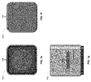
- FIG. 3 a illustrates a perspective view of a narrow-frame square camera housing, according to one embodiment.
- FIG. 3 b illustrates an alternative perspective view of the narrow-frame square camera housing, according to one embodiment.
- FIG. 3 c illustrates a rear perspective view of the narrow-frame square camera housing, according to one embodiment.
- FIG. 3 d illustrates an alternative rear perspective view of the narrow-frame square camera housing, according to one embodiment.
- FIG. 3 e illustrates a front view of the narrow-frame square camera housing, according to one embodiment.
- FIG. 3 f illustrates a rear view of the narrow-frame square camera housing, according to one embodiment.
- FIG. 3 g illustrates a side view of the narrow-frame square camera housing, according to one embodiment.
- FIG. 3 h illustrates an alternative side view of the narrow-frame square camera housing, according to one embodiment.
- FIG. 3 i illustrates a bottom view of the narrow-frame square camera housing, according to one embodiment.
- FIG. 3 j illustrates a top view of the narrow-frame square camera housing, according to one embodiment.
- FIG. 3 k illustrates a perspective view of a wide-frame square camera housing, according to one embodiment.
- FIG. 3 l illustrates an alternative perspective view of the wide-frame square camera housing, according to one embodiment.
- FIG. 3 m illustrates a rear perspective view of the wide-frame square camera housing, according to one embodiment.
- FIG. 3 n illustrates an alternative rear perspective view of the wide-frame square camera housing, according to one embodiment.
- FIG. 3 o illustrates a front view of the wide-frame square camera housing, according to one embodiment.
- FIG. 3 p illustrates a rear view of the wide-frame square camera housing, according to one embodiment.
- FIG. 3 q illustrates a side view of the wide-frame square camera housing, according to one embodiment.
- FIG. 3 r illustrates an alternative side view of the wide-frame square camera housing, according to one embodiment.
- FIG. 3 s illustrates a bottom view of the wide-frame square camera housing, according to one embodiment.
- FIG. 3 t illustrates a top view of the wide-frame square camera housing, according to one embodiment.
- FIG. 4 illustrates a latching mechanism for a square camera housing, according to one embodiment.
- FIG. 5 a illustrates the insertion of the square camera into the narrow-frame square camera housing, according to one embodiment.
- FIG. 5 b illustrates the camera inserted into the narrow-frame square camera housing in a first configuration, according to one embodiment.
- FIG. 5 c illustrates the camera inserted into the narrow-frame square camera housing in a second configuration, according to one embodiment.
- FIG. 5 d illustrates the insertion of the square camera into the wide-frame square camera housing, according to one embodiment.
- FIG. 5 e illustrates the camera inserted into the wide-frame square camera housing in a first configuration, according to one embodiment.
- FIG. 5 f illustrates the camera inserted into the wide-frame square camera housing in a second configuration, according to one embodiment.
- FIGS. 1 a to 1 d illustrate perspective views of an example square camera, according to one embodiment.
- the square camera 100 includes a camera lens 102 , an interface button 104 , and a display 106 .
- square camera refers to a camera with at least one substantially square cross-section in a two-dimensional plane.
- the square camera 100 which can be used with the square camera housing, includes a camera exterior that encompasses and protects the camera's internal electronics, which are further described in FIG. 2 .
- the camera exterior includes 6 surfaces (i.e. a front face, a left face, a right face, a back face, a top face, and a bottom face), wherein the exterior surfaces form a rectangular cuboid.
- both the front and rear surfaces of the square camera 100 are substantially square in shape.
- all camera surfaces may also have a substantially square profile, making the square camera 100 substantially cubic.
- only two of the six faces are square and the other faces may be other shapes, such as elongated rectangles.
- the square camera 100 can have a small form factor (e.g. a height of 2 cm to 9 cm, a width of 2 cm to 9 cm, and a depth of 2 cm to 9 cm) and is made of a rigid material such as plastic, aluminum, steel, or fiberglass. Additional camera features, such as the features described below, may be affixed to an exterior of the square camera.
- the square camera described herein includes features other than those described below.
- the square camera can include additional buttons or different interface features, such as a microphone opening to receive voice or other audio commands.
- FIG. 1 e illustrates a front view of the square camera, according to one embodiment.
- the front surface of the camera has a substantially square profile, such that all edges of the front surface are of roughly equal length.
- the front surface also includes a camera lens 102 , which includes an aperture that allows light to pass through the lens 214 and onto an image sensor 206 .
- the camera lens 102 can be any type of optical lens that facilitates capturing images or video, such as a wide-angle lens, an adjustable lens, a macro lens, and the like. While the camera lens 102 as shown in FIG. 1 e is located in the center of the front surface, the camera lens 102 may be located anywhere on the front surface of the camera 100 , or on any other surface.
- the camera lens 102 can protrude from the camera 100 or, as in the illustrated embodiment, can be flush with the front surface.
- FIG. 1 f illustrates a rear view of the square camera, according to one embodiment.
- the rear surface of the camera has a substantially square profile and has substantially similar dimensions to the front surface. While not shown in FIG. 1 f , the rear surface of the square camera may further include a user interface, such as a screen, button, dial, viewfinder, or light, or a communicative interface, such as a USB or HDMI slot.
- a user interface such as a screen, button, dial, viewfinder, or light
- a communicative interface such as a USB or HDMI slot.
- FIG. 1 g illustrates a top view of the square camera, according to one embodiment.
- the top surface has a substantially square profile with substantially similar dimensions to the front and rear surfaces; however, in other embodiments, the top surface may have a rectangular profile.
- the top surface features an interface button 104 and a display 106 .
- the interface button 104 allows a user to interact with the camera. By pressing the button, a user may take a picture or record video, power on or off the camera, save a photo, adjust the camera focus, or perform any other action relevant to recording or storing digital media.
- the interface button 104 may also be embodied as a knob, a switch, a dial, a touchscreen, a light (such as an LED), a speaker, or other forms of user interface.
- the camera may have more than one interface button 104 . Even though the interface button 104 is located on the top surface of the substantially square camera, the interface button 104 may be located in any position on any surface.
- the display (or screen) 106 allows the camera to output visual information to a user.
- the display 106 is located on the top surface of the square camera, however, the display 106 may be located on any surface of the camera 100 .
- FIG. 2 is a block diagram illustrating one embodiment of electronic components of a square camera 100 .
- the square camera 100 includes one or more processors 202 (generally, such as a digital signal processor or a microcontroller) that controls the operation and functionality of the camera.
- the processor 202 controls the operation of a lens and focus controller 204 , an image sensor (or image sensor array) 206 , a sensor controller 208 , a system memory 210 , an I/O controller hub 216 , and a synchronization interface 220 .
- the camera 204 includes components other than those illustrated herein.
- the image sensor 206 is configured to capture light incident upon the image sensor to produce image data based on control signals from the sensor controller 208 .
- the lens and focus controller 214 is configured to control the operation and configuration of a camera lens.
- the system memory 210 is configured to store executable computer instructions that, when executed by the processor 202 , perform the camera functionalities described herein.
- the camera 204 sends information (such as captured images and video) to and from the interface button 104 via the I/O controller hub.
- the processor 202 can store captured images and video in an external storage device 212 , or can output captured images or video for display on an external display 224 via a graphics adapter 222 .
- the synchronization interface 220 is configured to synchronize the camera 204 with other cameras or with other external devices, such as a remote control or a smart phone.
- FIG. 3 a to FIG. 3 d illustrate perspective views of an example narrow-frame square camera housing, according to one embodiment.
- square camera housing refers to a camera housing with at least one substantially square cross-section
- the square camera housing includes a housing body 300 , a mounting mechanism 302 , a latching mechanism 304 , and a plurality of openings 306 configured to accommodate the interface button 104 .
- the housing body 300 is a structure that secures the square camera 100 .
- the housing body 300 includes four walls or more (i.e., a top wall, a bottom wall, a left wall, and a right wall) that create a band around the square camera 100 .
- the housing body 300 may be missing one or more of these walls (such as the top wall or a side wall) such that the housing body 300 is in the form of a U-shape instead of a band.
- the walls of the housing body 300 do not fully encompass various surfaces of the square camera 100 (such as the top surface, right surface, and left surface of the camera).
- the walls of the housing body 300 fully encompass one or more surfaces of the square camera 100 .
- a housing body 300 may include a front wall or a rear wall to further secure the camera in the housing body.
- the housing body may include additional walls that form a hexagonal or octagonal housing to accommodate a similarly-shaped camera 100 .
- Additional features of the housing body 300 may include a housing lip, located along one or more interior edges of the body, to limit the depth to which the camera can be inserted into the housing body 300 .
- a housing lip along the perimeter of the housing body's front face prevents the square camera 100 from being pushed out of the housing body 300 when the camera 100 is inserted from the rear.
- the interior dimensions of the housing body 300 are similar to the exterior dimensions of the square camera frame, such that the square camera fits flush into the housing body. Furthermore, the housing body 300 in one example embodiment can have a small form factor (e.g. a height of 2 cm. to 10 cm., a width of 2 cm. to 10 cm., and a depth of 2 cm. to 10 cm.) and is lightweight (e.g. a weight of 25 to 150 grams).
- a small form factor e.g. a height of 2 cm. to 10 cm., a width of 2 cm. to 10 cm., and a depth of 2 cm. to 10 cm.
- lightweight e.g. a weight of 25 to 150 grams.
- the latching mechanism 304 can be configured in a open position such that the square camera can be inserted or removed from the housing body 300 , or can be configured to a closed position such that the square camera can be compressibly secured within the housing body.
- the housing body 300 can be made of a flexible material (e.g. plastic, polymer, metal, wood, or any other suitable material) that allows the walls to sufficiently deflect when the latching mechanism 304 is configured in an open position, allowing for the insertion or removal of the square camera from the housing body.
- the flexible material may exhibit material properties suitable for protecting the square camera 100 secured in the square camera housing from physical shock, abrasion, vibration, or environmental damage (e.g. water damage, dust, etc.).
- the latching mechanism 304 can be made of plastic, polymer, metal, wood, or any other suitable material.
- housing body 300 includes a description of separate walls, this does not necessarily imply that the housing body includes separate wall components welded, fastened, or otherwise connected. In one embodiment, the housing body 300 is fabricated as a single piece with no discernible boundaries between walls.
- FIG. 3 e to FIG. 3 j illustrate views of the narrow-frame square camera housing, according to one embodiment.
- the figures illustrate features connected to the housing body 300 , including a plurality of protrusions 302 , a latching mechanism 304 , and a plurality of openings 306 to accommodate the camera interface button 104 .
- a mounting mechanism allows the housing body 300 to be coupled to another object, such as bodywear, sporting equipment, or a vehicle.
- the mounting mechanism includes two protrusions 302 on the bottom surface of the housing body 300 . As seen in FIG. 3 g and FIG. 3 h , each protrusion 302 includes an aligning screw hole. The protrusions 302 are spaced such that the mounting mechanism can be coupled to a reciprocal mounting mechanism including additional protrusions that interlock with the protrusions 302 .
- the additional protrusions can also include screw holes that align with the screw holes of the protrusions 302 such that a screw (e.g., a turnable handscrew) may be inserted through the interlocking protrusions, coupling the housing body 300 to the reciprocal mounting mechanism.
- a screw e.g., a turnable handscrew
- the housing body 300 can pivot rotationally relative to the reciprocal mounting device.
- the turnable handscrew is in a locked position, the housing body 300 is fixed in position relative to the reciprocal mounting device.
- the plurality of openings 306 are openings in the walls of the housing frame 300 that allow the square camera 100 to be oriented in multiple positions relative to the square camera housing such that the interface button 104 is accessible to a user through one of the openings 306 .
- the plurality of openings are each rectangular in shape and include a semi-elliptical cutout that accommodates the interface button 104 .
- other embodiments of the plurality of openings 306 may be any shape that accommodates one or more camera interfaces.
- the plurality of openings are located in the same relative position on each surface of the housing body 300 (e.g., on the top surface, the left surface, and the right surface) such that the camera body can be inserted and secured in the body in one of a plurality of orientations.
- the plurality of openings 306 may allow the square camera 100 to be oriented in the frame vertically upright, rotated 90 degrees clockwise from vertical, or rotated 90 degrees counterclockwise from vertical.
- the plurality of openings may be arranged such that the square camera 100 may be oriented in additional or alternative positions.
- a pliable waterproof or water-resistant material may be placed over the plurality of openings 306 to protect the camera from water or dust but not impede access to the interface button 104 .
- the square camera 100 is configured to identify an orientation of the camera within the housing body 300 .
- the square camera 100 can adjust the portion of the image sensor used to capture an image based on the identified orientation. For instance, if the square camera is inserted into the camera housing in an upright configuration, the square camera can capture an image from light incident upon a 16:9 ratio portion of the image sensor (and accordingly, can disregard light incident upon other portions of the image sensor, or can maintain image data from light incident upon such portions for use in subsequent image processing).
- the square camera can capture an image from light incident upon a 9:16 ratio portion of the image sensor, for instance for use in subsequent image processing to produce a 16:9 image.
- the square camera 100 can include a square image sensor, and can be configured to adjust the portion of the image sensor used to capture an image.
- the housing body 300 may not include a plurality of openings 306 .
- the housing body 300 may include one or more button interfaces that allow for user interaction with the square camera 100 .
- the top wall, left wall, and right wall of the housing can each include one or more buttons or other compressible components configured to align with a camera interface when the camera is inserted into the camera housing in an associated orientation and to allow a user of the housing to interact with the camera interface using the compressible housing components.
- FIG. 3 k to FIG. 3 t illustrate an embodiment of a wide-frame square camera housing.
- the wide-frame square camera housing has the same functionality as the narrow-frame square camera housing described in FIG. 3 a to FIG. 3 j .
- the wide-frame square camera housing includes walls that completely encompass the top, bottom, and side surfaces of the square camera 100 .
- Each wall of the wide-frame camera housing encompasses each corresponding side of the square camera 100 .
- the walls of the wide-frame housing body 300 are substantially square in shape.
- the interior dimensions of the housing body 300 are similar to the exterior dimensions of the square camera frame, such that the square camera fits flush within the housing body.
- the housing body 300 in one example embodiment has a small form factor (e.g., a height of 2 cm. to 10 cm., a width of 2 cm. to 10 cm., and a depth of 2 cm. to 10 cm.) and is lightweight (e.g., a weight of 25 to 150 grams).
- a small form factor e.g., a height of 2 cm. to 10 cm., a width of 2 cm. to 10 cm., and a depth of 2 cm. to 10 cm.
- is lightweight e.g., a weight of 25 to 150 grams.
- FIG. 4 illustrates a latching mechanism 304 for a square camera housing, according to one embodiment.
- the latching mechanism 304 includes a first hinge mechanism 402 coupled to a top wall of the housing body 300 and a second hinge mechanism 404 coupled to a side wall of the housing body.
- the latching mechanism 304 may be located on any surface of the housing body (for instance, the latching mechanism 304 can be located exclusively on the top wall, a side wall, or the bottom wall, or can be located at the intersection of a side wall and the bottom wall).
- the first 402 and the second 404 hinge mechanisms interlock such that when the latching mechanism 304 is configured in an open position, a gap 406 between the top wall and the side wall of the housing body 300 increases (or expands), increasing the inside perimeter of the housing body 300 and allowing for the insertion and removal of the square camera 100 from the housing body 300 .
- the gap 406 decreases (or shrinks), decreasing the inside perimeter of the housing body 300 and securing the squares camera 100 within the housing body 300 .
- the exteriors of both hinge mechanisms can be smooth and featureless, such that the latching mechanism does not catch on other objects or the surrounding environment.
- the latching mechanism 304 can be unlocked by lifting the first hinge mechanism 402 .
- the camera housing does not require a latching mechanism.
- the camera housing includes a flexible/stretchable compressive band configured to compressibly secure a camera is within the housing.
- the housing can be stretchably expanded to accommodate the insertion of the camera, and released to compressibly wrap around the exterior of the camera, securing the camera within the housing.
- FIG. 5 a illustrates the insertion of the square camera into the narrow-frame square camera housing, according to one embodiment.
- the latching mechanism 304 is unlocked and the square camera 100 is inserted into the housing body 300 in one of a plurality of orientations relative to the housing body 300 .
- the square camera 100 may be inserted into the square camera housing through the front opening of the housing or the rear opening of the housing.
- a housing lip on one or more wall interiors, e.g., along an edge of each wall, may regulate the position of the square camera 100 within the housing.
- the camera lens 102 is facing front in the exemplary orientations, the camera may be inserted such that the lens is facing the rear surface of the housing body 300 .
- the square camera housing may accommodate the square camera 100 in additional or alternative orientations.
- the latching mechanism 304 is closed.
- the housing body 300 may be connected to a reciprocal mounting device either before or after the camera is inserted into the body.
- FIG. 5 b illustrates the camera inserted into the narrow-frame square camera housing in a first configuration, according to one embodiment.
- the square camera 100 is inserted vertically upright into the square camera housing.
- FIG. 5 c illustrates the camera inserted into the narrow-frame square camera housing in a second configuration, according to one embodiment.
- the second configuration may include rotating the square camera 100 90 degrees clockwise or 90 degrees counterclockwise around the front-rear axis.
- the square camera 100 may be inserted into the square housing body 300 in other configurations not disclosed in FIG. 5 c.
- FIG. 5 b and FIG. 5 c illustrate the square camera 100 secured in different orientations within the narrow-frame square camera mount.
- FIG. 5 b shows the square camera 100 secured vertically upright in the square camera mount
- FIG. 5 c shows the camera secured while rotated 90 degrees clockwise in the camera mount.
- FIG. 5 d - FIG. 5 f illustrate the square camera 100 being inserted and secured in the wide-frame square camera mount.
- Coupled along with its derivatives.
- the term “coupled” as used herein is not necessarily limited to two or more elements being in direct physical or electrical contact. Rather, the term “coupled” may also encompass two or more elements that are not in direct contact with each other, but yet still co-operate or interact with each other, or are structured to provide a thermal conduction path between the elements.
- the terms “includes,” “comprising,” “includes,” “including,” “has,” “having,” or any other variation thereof, are intended to cover a non-exclusive inclusion.
- a process, method, article, or apparatus that includes a list of elements is not necessarily limited to only these elements but may also include other elements not expressly listed to such process, method, article, or apparatus.
- any reference to “one embodiment” or “an embodiment” means that a particular element, feature, structure, or characteristic described in connection with the embodiment is included in at least one embodiment.
- the appearances of the phrase “in one embodiment” in various places in the specification are not necessarily all referring to the same embodiment.
Abstract
Description
Claims (22)
Priority Applications (5)
| Application Number | Priority Date | Filing Date | Title |
|---|---|---|---|
| US14/536,683 US9282226B2 (en) | 2014-01-06 | 2014-11-10 | Camera housing for a square-profile camera |
| US14/947,766 US9635226B2 (en) | 2014-01-06 | 2015-11-20 | Camera housing for a square-profile camera |
| US15/212,322 US9521302B2 (en) | 2014-01-06 | 2016-07-18 | Camera system with a square-profile camera |
| US15/464,004 US10306115B2 (en) | 2014-01-06 | 2017-03-20 | Camera housing for a square-profile camera |
| US16/381,553 US20190238729A1 (en) | 2014-01-06 | 2019-04-11 | Camera Housing for a Square-Profile Camera |
Applications Claiming Priority (2)
| Application Number | Priority Date | Filing Date | Title |
|---|---|---|---|
| US14/148,536 US8992102B1 (en) | 2014-01-06 | 2014-01-06 | Camera housing for a square-profile camera |
| US14/536,683 US9282226B2 (en) | 2014-01-06 | 2014-11-10 | Camera housing for a square-profile camera |
Related Parent Applications (1)
| Application Number | Title | Priority Date | Filing Date |
|---|---|---|---|
| US14/148,536 Continuation US8992102B1 (en) | 2014-01-06 | 2014-01-06 | Camera housing for a square-profile camera |
Related Child Applications (1)
| Application Number | Title | Priority Date | Filing Date |
|---|---|---|---|
| US14/947,766 Continuation US9635226B2 (en) | 2014-01-06 | 2015-11-20 | Camera housing for a square-profile camera |
Publications (2)
| Publication Number | Publication Date |
|---|---|
| US20150195436A1 US20150195436A1 (en) | 2015-07-09 |
| US9282226B2 true US9282226B2 (en) | 2016-03-08 |
Family
ID=52707764
Family Applications (7)
| Application Number | Title | Priority Date | Filing Date |
|---|---|---|---|
| US14/148,536 Active US8992102B1 (en) | 2014-01-06 | 2014-01-06 | Camera housing for a square-profile camera |
| US29/504,319 Active USD750687S1 (en) | 2014-01-06 | 2014-10-03 | Camera |
| US14/536,683 Active US9282226B2 (en) | 2014-01-06 | 2014-11-10 | Camera housing for a square-profile camera |
| US14/947,766 Active US9635226B2 (en) | 2014-01-06 | 2015-11-20 | Camera housing for a square-profile camera |
| US15/212,322 Active US9521302B2 (en) | 2014-01-06 | 2016-07-18 | Camera system with a square-profile camera |
| US15/464,004 Active 2034-06-20 US10306115B2 (en) | 2014-01-06 | 2017-03-20 | Camera housing for a square-profile camera |
| US16/381,553 Abandoned US20190238729A1 (en) | 2014-01-06 | 2019-04-11 | Camera Housing for a Square-Profile Camera |
Family Applications Before (2)
| Application Number | Title | Priority Date | Filing Date |
|---|---|---|---|
| US14/148,536 Active US8992102B1 (en) | 2014-01-06 | 2014-01-06 | Camera housing for a square-profile camera |
| US29/504,319 Active USD750687S1 (en) | 2014-01-06 | 2014-10-03 | Camera |
Family Applications After (4)
| Application Number | Title | Priority Date | Filing Date |
|---|---|---|---|
| US14/947,766 Active US9635226B2 (en) | 2014-01-06 | 2015-11-20 | Camera housing for a square-profile camera |
| US15/212,322 Active US9521302B2 (en) | 2014-01-06 | 2016-07-18 | Camera system with a square-profile camera |
| US15/464,004 Active 2034-06-20 US10306115B2 (en) | 2014-01-06 | 2017-03-20 | Camera housing for a square-profile camera |
| US16/381,553 Abandoned US20190238729A1 (en) | 2014-01-06 | 2019-04-11 | Camera Housing for a Square-Profile Camera |
Country Status (4)
| Country | Link |
|---|---|
| US (7) | US8992102B1 (en) |
| EP (1) | EP3092527B1 (en) |
| CN (1) | CN106164768A (en) |
| WO (1) | WO2015102888A1 (en) |
Cited By (26)
| Publication number | Priority date | Publication date | Assignee | Title |
|---|---|---|---|---|
| USD776738S1 (en) * | 2015-05-11 | 2017-01-17 | Gopro, Inc. | Camera housing |
| USD785068S1 (en) | 2015-09-02 | 2017-04-25 | Go Cube, Inc. | Camera housing |
| USD791211S1 (en) | 2015-12-25 | 2017-07-04 | Nikon Corporation | Digital camera |
| USD803925S1 (en) * | 2015-12-25 | 2017-11-28 | Nikon Corporation | Digital camera |
| USD816751S1 (en) | 2015-05-11 | 2018-05-01 | Gopro, Inc. | Camera housing |
| USD818029S1 (en) | 2015-12-25 | 2018-05-15 | Nikon Corporation | Digital camera |
| USD825636S1 (en) * | 2016-12-19 | 2018-08-14 | Decathlon | Video camera |
| USD858603S1 (en) * | 2015-07-24 | 2019-09-03 | iSmart Alarm, Inc. | Security camera |
| US10582094B2 (en) * | 2016-09-21 | 2020-03-03 | Gopro, Inc. | Camera mount stand and cover |
| USD894256S1 (en) | 2018-08-31 | 2020-08-25 | Gopro, Inc. | Camera mount |
| USD905786S1 (en) | 2018-08-31 | 2020-12-22 | Gopro, Inc. | Camera mount |
| USD905780S1 (en) * | 2019-01-24 | 2020-12-22 | Polycom, Inc. | Videoconferencing camera |
| US10928711B2 (en) | 2018-08-07 | 2021-02-23 | Gopro, Inc. | Camera and camera mount |
| USD911411S1 (en) | 2019-09-13 | 2021-02-23 | Gopro, Inc. | Camera housing |
| USD917598S1 (en) * | 2019-07-23 | 2021-04-27 | Tianjin HuaLai Technology Co., Ltd | Camera set |
| USD921084S1 (en) | 2019-09-13 | 2021-06-01 | Gopro, Inc. | Camera housing |
| USD946071S1 (en) | 2020-06-30 | 2022-03-15 | Gopro, Inc. | Camera housing |
| USD946072S1 (en) | 2020-08-10 | 2022-03-15 | Gopro, Inc. | Camera housing |
| USD953406S1 (en) | 2019-09-30 | 2022-05-31 | Gopro, Inc. | Camera housing |
| USD953404S1 (en) | 2020-08-14 | 2022-05-31 | Gopro, Inc. | Camera housing |
| USD954132S1 (en) | 2020-07-31 | 2022-06-07 | Gopro, Inc. | Camera housing |
| USD967227S1 (en) * | 2020-09-04 | 2022-10-18 | Tianjin Hualai Technology Co., Ltd. | Smart camera |
| USD991318S1 (en) | 2020-08-14 | 2023-07-04 | Gopro, Inc. | Camera |
| USD997232S1 (en) | 2019-09-17 | 2023-08-29 | Gopro, Inc. | Camera |
| USD1014603S1 (en) | 2019-09-13 | 2024-02-13 | Gopro, Inc. | Camera housing |
| USD1025173S1 (en) | 2022-08-09 | 2024-04-30 | Gopro, Inc. | Microphone cover of a camera housing |
Families Citing this family (48)
| Publication number | Priority date | Publication date | Assignee | Title |
|---|---|---|---|---|
| US20150317305A1 (en) * | 2014-05-01 | 2015-11-05 | Gilbert R. Ortiz | Language Translation Assembly |
| BR102014016654B1 (en) * | 2014-07-03 | 2022-03-08 | Samsung Eletrônica Da Amazônia Ltda | MOBILE DEVICE SYSTEM WITH REMOVABLE CAMERA AND ITS METHOD OF USE |
| GB201507347D0 (en) * | 2015-04-29 | 2015-06-10 | Tomtom Int Bv | Camera mounting system |
| USD785069S1 (en) | 2015-09-01 | 2017-04-25 | Avant Technology, Inc. | Camera housing |
| US10101637B2 (en) | 2015-09-11 | 2018-10-16 | Avant Technology, Inc. | Camera case with removable carrier, filter receiver, external battery and supplemental memory storage |
| USD837864S1 (en) * | 2015-09-14 | 2019-01-08 | Fanglei Ge | IP camera |
| USD831868S1 (en) | 2015-09-17 | 2018-10-23 | Lume Cube, Inc. | Compact external light |
| US10704745B2 (en) | 2015-10-13 | 2020-07-07 | Lume Cube, Inc. | Mobile light source |
| US20170162230A1 (en) * | 2015-12-04 | 2017-06-08 | Livestream LLC | Interactive digital camera for live crop editing and recording of video streams |
| US9995990B2 (en) | 2015-12-15 | 2018-06-12 | Gopro, Inc. | Removable camera lens cover |
| USD848500S1 (en) * | 2016-05-26 | 2019-05-14 | Gopro, Inc. | Camera mount for a square profile camera |
| US10555062B2 (en) * | 2016-08-31 | 2020-02-04 | Panasonic Intellectual Property Management Co., Ltd. | Sound pick up device with sound blocking shields and imaging device including the same |
| US10203588B2 (en) * | 2016-09-16 | 2019-02-12 | Gopro, Inc. | Drainage channel for a submersible camera with drainage ports on two surfaces |
| US9864257B1 (en) | 2016-09-19 | 2018-01-09 | Gopro, Inc. | Camera frame with side door |
| CN107914274B (en) * | 2016-10-11 | 2021-05-04 | 芋头科技(杭州)有限公司 | Assembly method of egg-shaped robot |
| WO2018071611A1 (en) * | 2016-10-12 | 2018-04-19 | Elias James Harrison | Camera holder |
| USD826206S1 (en) * | 2016-12-29 | 2018-08-21 | Facebook, Inc. | Speaker device |
| JP1598118S (en) * | 2017-03-02 | 2018-02-19 | ||
| US20180316834A1 (en) * | 2017-04-28 | 2018-11-01 | Ryan GRABOW | Video system and method for allowing users, including medical professionals, to capture video of surgical procedures |
| GR1009256B (en) * | 2017-05-30 | 2018-03-23 | Γαρυφαλια Χρηστου Μινου | Defensive security camera |
| USD893576S1 (en) * | 2017-10-26 | 2020-08-18 | Centrica Hive Limited | Camera |
| USD890835S1 (en) | 2017-12-28 | 2020-07-21 | Gopro, Inc. | Camera |
| USD995601S1 (en) * | 2018-06-05 | 2023-08-15 | Huddly As | Smart camera |
| AU2019284759A1 (en) * | 2018-06-12 | 2021-01-07 | Commscope Technologies Llc | Telecommunications enclosure with a separate mountable hinge |
| USD907680S1 (en) | 2018-08-31 | 2021-01-12 | Gopro, Inc. | Camera |
| USD907101S1 (en) | 2019-06-11 | 2021-01-05 | Gopro, Inc. | Camera |
| USD903740S1 (en) | 2018-09-14 | 2020-12-01 | Gopro, Inc. | Camera |
| USD849110S1 (en) | 2018-09-14 | 2019-05-21 | Davinci Ii Csj, Llc | Camera |
| USD922352S1 (en) * | 2019-01-04 | 2021-06-15 | Dolby Laboratories Licensing Corporation | Speaker |
| USD885469S1 (en) * | 2019-03-15 | 2020-05-26 | Shenzhen Jike Digital Technology Co., Ltd. | Outside shooting light |
| CN217470540U (en) | 2019-09-18 | 2022-09-20 | 高途乐公司 | Image capturing apparatus and door assembly for the same |
| USD939325S1 (en) * | 2019-10-11 | 2021-12-28 | John F. Bently | Mounting holder |
| USD928733S1 (en) * | 2019-11-15 | 2021-08-24 | Logitech Europe S.A. | Audio device |
| JP2021107874A (en) * | 2019-12-27 | 2021-07-29 | キヤノン株式会社 | Imaging apparatus and method for controlling the same, program, and storage medium |
| USD917603S1 (en) | 2020-01-27 | 2021-04-27 | Amazon Technologies, Inc. | Camera |
| US11425286B2 (en) | 2020-03-31 | 2022-08-23 | Gopro, Inc. | Housing assembly for image capture devices |
| US11630376B2 (en) | 2020-06-18 | 2023-04-18 | Gopro, Inc. | Removable lens accessories for image capture devices |
| US11782327B2 (en) | 2020-07-02 | 2023-10-10 | Gopro, Inc. | Removable battery door assemblies for image capture devices |
| USD974450S1 (en) * | 2020-08-28 | 2023-01-03 | Gopro, Inc. | Camera lens attachment |
| USD967890S1 (en) * | 2020-08-28 | 2022-10-25 | Gopro, Inc. | Camera lens attachment |
| USD996493S1 (en) | 2020-12-07 | 2023-08-22 | Applied Materials, Inc. | Live streaming camera |
| JP1705857S (en) * | 2021-04-23 | 2022-01-24 | Surveillance camera | |
| USD997902S1 (en) | 2021-09-14 | 2023-09-05 | Hewlett-Packard Development Company, L.P. | Speaker |
| USD991250S1 (en) | 2021-09-14 | 2023-07-04 | Hewlett-Packard Development Company, L.P. | Conference device |
| USD986308S1 (en) * | 2021-09-14 | 2023-05-16 | Hewlett-Packard Development Company, L.P. | Camera |
| USD989047S1 (en) | 2021-09-14 | 2023-06-13 | Hewlett-Packard Development Company, L.P. | Microphone |
| USD969195S1 (en) * | 2021-09-22 | 2022-11-08 | Yanxuan Chen | Hidden camera |
| TWD221403S (en) | 2021-12-02 | 2022-10-01 | 宏智科創股份有限公司 | Panoramic camera |
Citations (57)
| Publication number | Priority date | Publication date | Assignee | Title |
|---|---|---|---|---|
| US1612277A (en) | 1922-11-03 | 1926-12-28 | Drop Head Projector Company | Housing for portable motion-picture machines |
| US3508482A (en) | 1967-10-30 | 1970-04-28 | Eastman Kodak Co | Handle and battery compartment for photographic apparatus |
| US4091402A (en) | 1976-12-20 | 1978-05-23 | Philip Siegel | Camera support bracket and flash unit mounting device |
| US4208028A (en) | 1974-09-16 | 1980-06-17 | Garrett Brown | Support apparatus |
| US4646141A (en) | 1985-01-28 | 1987-02-24 | U.S. Philips Corporation | Television camera |
| US4733259A (en) | 1987-03-16 | 1988-03-22 | Ng Chong Y | Tiltable tripod attachment for a camera |
| JPH05304625A (en) * | 1992-04-24 | 1993-11-16 | Sony Corp | Video camera |
| US5400234A (en) | 1994-03-09 | 1995-03-21 | Yu; Abraham | Light |
| US5808663A (en) | 1997-01-21 | 1998-09-15 | Dell Computer Corporation | Multimedia carousel for video conferencing and multimedia presentation applications |
| USD441386S1 (en) | 1998-04-23 | 2001-05-01 | Fujitsu General Limited | Body of a video camera |
| USD442982S1 (en) | 2000-02-14 | 2001-05-29 | Elmo Company Limited | Surveillance camera body |
| US6315180B1 (en) * | 1997-08-28 | 2001-11-13 | D. Scott Watkins | Camera mount |
| US20020046218A1 (en) | 1999-06-23 | 2002-04-18 | Scott Gilbert | System for digitally capturing and recording panoramic movies |
| US20030156212A1 (en) * | 2002-02-20 | 2003-08-21 | Yasuhiro Kingetsu | Digital camera |
| US20040223752A1 (en) | 2003-05-05 | 2004-11-11 | Ghanouni Amir Saied | Accessory assembly for photographic equipment |
| USD504904S1 (en) | 2003-09-02 | 2005-05-10 | Ikegami Tsushinki Co., Ltd. | Surveillance camera |
| USD515121S1 (en) | 2003-11-07 | 2006-02-14 | Scimeasure Analytical Systems, Inc. | CCD camera |
| USD515613S1 (en) | 2003-04-24 | 2006-02-21 | Holmes Joseph T | Webcam mount for flexible positioning |
| US20060257137A1 (en) | 2005-05-10 | 2006-11-16 | Fromm Wayne G | Apparatus for supporting a camera by hand |
| US20070140686A1 (en) * | 2005-12-19 | 2007-06-21 | Fujifilm Corporation | Camera |
| USD551969S1 (en) | 2005-06-28 | 2007-10-02 | The Procter & Gamble Company | Carton |
| US20080117328A1 (en) | 2006-11-21 | 2008-05-22 | Michael Daoud | Retractable camera arm |
| USD576486S1 (en) | 2007-10-18 | 2008-09-09 | Sony Corporation | Headphone cork packaging block |
| USD577731S1 (en) | 2006-09-15 | 2008-09-30 | Innovative Office Products, Inc. | Boom extension arm |
| USD577729S1 (en) | 2006-10-06 | 2008-09-30 | Innovative Office Products, Inc. | Boom extension arm |
| US20080248703A1 (en) | 2007-04-09 | 2008-10-09 | Sean Anthony Joseph Russell | Buoyant mount for supporting articles in particular cinematographic apparatus upon or within a body of water. |
| USD596217S1 (en) | 2008-04-30 | 2009-07-14 | Samsung Techwin Co., Ltd. | Digital camera |
| US20100060747A1 (en) | 2008-07-07 | 2010-03-11 | Woodman Nicholas D | Camera Housing With Integrated Expansion Module |
| US20100061711A1 (en) | 2008-07-07 | 2010-03-11 | Woodman Nicholas D | Mount System For Attaching Camera To A Sport Board |
| USD616480S1 (en) | 2008-12-10 | 2010-05-25 | Panasonic Corporation | Network camera |
| USD616742S1 (en) | 2008-02-01 | 2010-06-01 | Target Brands, Inc. | Cover |
| US7728905B2 (en) * | 2006-03-03 | 2010-06-01 | Fujitsu Limited | Image capturing apparatus having an image capturing system disposed close to an illumination system |
| US20110001834A1 (en) | 2009-07-03 | 2011-01-06 | Stephanie Herrell | Four-sided photography camera |
| US20110042530A1 (en) | 2009-08-19 | 2011-02-24 | Mark Phillips | Flexipod with flexible bendable legs with a gripping surface |
| US20110129210A1 (en) | 2009-12-01 | 2011-06-02 | Dr. Elliot McGucken | Heros journey 9shooter bracket and totem potem pole micro mini mount apparatus, system, and method for connecting multiple cameras, stills cameras, video cameras, DSLRs, monitors, microphones, flashes, radio receivers, recording devices, mounts, power packs, and more |
| US20110216195A1 (en) | 2010-03-05 | 2011-09-08 | Chihiro Tanaka | Image-capturing device and in-vehicle camera |
| US20110317065A1 (en) | 2010-06-25 | 2011-12-29 | Omnivision Technologies, Inc. | Reinforcement structure for wafer-level camera module |
| USD680097S1 (en) | 2011-07-27 | 2013-04-16 | Gp Acoustics International Limited | Loudspeaker |
| US8467675B2 (en) | 2011-03-04 | 2013-06-18 | Hong Fu Jin Precision Industry (Shenzhen) Co., Ltd. | Camera module |
| US20130186310A1 (en) | 2012-01-24 | 2013-07-25 | Dimitrios Lymberis | Hunting utility tray and folding arm assembly |
| USD690280S1 (en) | 2012-01-09 | 2013-09-24 | Imation Corp. | Combined audio player and speaker |
| US8542308B2 (en) * | 2008-07-17 | 2013-09-24 | Samsung Electronics Co., Ltd. | Digital photographing apparatus with lens unit configured for flexible printed circuit boards having different lengths |
| US8544643B2 (en) * | 2009-12-21 | 2013-10-01 | Zear Corporation Limited | Waterproof camera case with a lock mechanism |
| USD700166S1 (en) | 2011-08-19 | 2014-02-25 | Brookstone Purchasing, Inc. | Audio speaker |
| US20140060582A1 (en) * | 2011-03-10 | 2014-03-06 | Evan Hartranft | Integrated automotive system, nozzle assembly and remote control method for cleaning an image sensor's exterior or objective lens surface |
| US8743277B2 (en) * | 2011-06-03 | 2014-06-03 | Canon Kabushiki Kaisha | Electronic apparatus |
| US8792003B2 (en) * | 2010-02-12 | 2014-07-29 | Sony Corporation | Camera device |
| USD713868S1 (en) | 2013-06-19 | 2014-09-23 | Amaryllo International B.V. | Wireless IP camera |
| USD718617S1 (en) | 2013-02-02 | 2014-12-02 | Sweet Concepts Limited | Confection container |
| US9004783B1 (en) | 2013-10-15 | 2015-04-14 | Gopro, Inc. | Camera mountable arm |
| USD727387S1 (en) | 2014-03-21 | 2015-04-21 | Panasonic Intellectual Property Management Co., Ltd. | Monitoring camera |
| USD727991S1 (en) | 2014-03-21 | 2015-04-28 | Panasonic Intellectual Property Management Co., Ltd. | Monitoring camera |
| US20150122849A1 (en) * | 2013-11-02 | 2015-05-07 | Russell Jones | Aquatic equipment-mounting headgear |
| USD729059S1 (en) | 2013-02-02 | 2015-05-12 | Sweet Concepts Limited | Confection container |
| USD729762S1 (en) | 2013-07-31 | 2015-05-19 | Shenzhen Rapoo Technology Co., Ltd. | Audio amplifier |
| USD729761S1 (en) | 2013-07-31 | 2015-05-19 | Shenzhen Rapoo Technology Co., Ltd. | Audio amplifier |
| USD730423S1 (en) | 2014-01-05 | 2015-05-26 | C & A Marketing | Cubic action camera |
Family Cites Families (11)
| Publication number | Priority date | Publication date | Assignee | Title |
|---|---|---|---|---|
| JPS534625A (en) | 1976-06-30 | 1978-01-17 | Teruhoodo Gibu Angasu | Number printing mechanism and printer therewith |
| JP2006140677A (en) * | 2004-11-11 | 2006-06-01 | Matsushita Electric Ind Co Ltd | Camera apparatus |
| US8368748B2 (en) * | 2005-11-21 | 2013-02-05 | Kenneth Kam-Sing Ho | Protector of handheld electronic devices |
| JP2008109364A (en) * | 2006-10-25 | 2008-05-08 | Opt Kk | Camera server system, processing method for data, and camera server |
| US8374495B2 (en) * | 2009-06-04 | 2013-02-12 | Sanwa Technologies Limited | User-configurable waterproof camera case |
| JP4910039B2 (en) * | 2009-12-25 | 2012-04-04 | 東芝テリー株式会社 | Industrial small electronic imaging camera |
| JP5494051B2 (en) * | 2010-03-15 | 2014-05-14 | オムロン株式会社 | Imaging device |
| US20140313377A1 (en) * | 2011-11-09 | 2014-10-23 | Mark Ross Hampton | In relation to a lens system for a camera |
| US8718457B2 (en) | 2012-05-24 | 2014-05-06 | Unruly, LLC | Camera case |
| US20140066144A1 (en) * | 2012-09-05 | 2014-03-06 | Uncommon Llc | Waterproof Phone Case |
| US8837928B1 (en) * | 2013-07-23 | 2014-09-16 | Gopro, Inc. | Camera housing |
-
2014
- 2014-01-06 US US14/148,536 patent/US8992102B1/en active Active
- 2014-10-03 US US29/504,319 patent/USD750687S1/en active Active
- 2014-11-10 US US14/536,683 patent/US9282226B2/en active Active
- 2014-12-16 EP EP14876907.8A patent/EP3092527B1/en active Active
- 2014-12-16 CN CN201480072371.9A patent/CN106164768A/en active Pending
- 2014-12-16 WO PCT/US2014/070655 patent/WO2015102888A1/en active Application Filing
-
2015
- 2015-11-20 US US14/947,766 patent/US9635226B2/en active Active
-
2016
- 2016-07-18 US US15/212,322 patent/US9521302B2/en active Active
-
2017
- 2017-03-20 US US15/464,004 patent/US10306115B2/en active Active
-
2019
- 2019-04-11 US US16/381,553 patent/US20190238729A1/en not_active Abandoned
Patent Citations (59)
| Publication number | Priority date | Publication date | Assignee | Title |
|---|---|---|---|---|
| US1612277A (en) | 1922-11-03 | 1926-12-28 | Drop Head Projector Company | Housing for portable motion-picture machines |
| US3508482A (en) | 1967-10-30 | 1970-04-28 | Eastman Kodak Co | Handle and battery compartment for photographic apparatus |
| US4208028A (en) | 1974-09-16 | 1980-06-17 | Garrett Brown | Support apparatus |
| US4091402A (en) | 1976-12-20 | 1978-05-23 | Philip Siegel | Camera support bracket and flash unit mounting device |
| US4646141A (en) | 1985-01-28 | 1987-02-24 | U.S. Philips Corporation | Television camera |
| US4733259A (en) | 1987-03-16 | 1988-03-22 | Ng Chong Y | Tiltable tripod attachment for a camera |
| JPH05304625A (en) * | 1992-04-24 | 1993-11-16 | Sony Corp | Video camera |
| US5400234A (en) | 1994-03-09 | 1995-03-21 | Yu; Abraham | Light |
| US5808663A (en) | 1997-01-21 | 1998-09-15 | Dell Computer Corporation | Multimedia carousel for video conferencing and multimedia presentation applications |
| US6315180B1 (en) * | 1997-08-28 | 2001-11-13 | D. Scott Watkins | Camera mount |
| USD441386S1 (en) | 1998-04-23 | 2001-05-01 | Fujitsu General Limited | Body of a video camera |
| US20020046218A1 (en) | 1999-06-23 | 2002-04-18 | Scott Gilbert | System for digitally capturing and recording panoramic movies |
| USD442982S1 (en) | 2000-02-14 | 2001-05-29 | Elmo Company Limited | Surveillance camera body |
| US20030156212A1 (en) * | 2002-02-20 | 2003-08-21 | Yasuhiro Kingetsu | Digital camera |
| USD515613S1 (en) | 2003-04-24 | 2006-02-21 | Holmes Joseph T | Webcam mount for flexible positioning |
| US20040223752A1 (en) | 2003-05-05 | 2004-11-11 | Ghanouni Amir Saied | Accessory assembly for photographic equipment |
| USD504904S1 (en) | 2003-09-02 | 2005-05-10 | Ikegami Tsushinki Co., Ltd. | Surveillance camera |
| USD515121S1 (en) | 2003-11-07 | 2006-02-14 | Scimeasure Analytical Systems, Inc. | CCD camera |
| US20060257137A1 (en) | 2005-05-10 | 2006-11-16 | Fromm Wayne G | Apparatus for supporting a camera by hand |
| USD551969S1 (en) | 2005-06-28 | 2007-10-02 | The Procter & Gamble Company | Carton |
| US20070140686A1 (en) * | 2005-12-19 | 2007-06-21 | Fujifilm Corporation | Camera |
| US7728905B2 (en) * | 2006-03-03 | 2010-06-01 | Fujitsu Limited | Image capturing apparatus having an image capturing system disposed close to an illumination system |
| USD577731S1 (en) | 2006-09-15 | 2008-09-30 | Innovative Office Products, Inc. | Boom extension arm |
| USD577729S1 (en) | 2006-10-06 | 2008-09-30 | Innovative Office Products, Inc. | Boom extension arm |
| US20080117328A1 (en) | 2006-11-21 | 2008-05-22 | Michael Daoud | Retractable camera arm |
| US20080248703A1 (en) | 2007-04-09 | 2008-10-09 | Sean Anthony Joseph Russell | Buoyant mount for supporting articles in particular cinematographic apparatus upon or within a body of water. |
| USD576486S1 (en) | 2007-10-18 | 2008-09-09 | Sony Corporation | Headphone cork packaging block |
| USD616742S1 (en) | 2008-02-01 | 2010-06-01 | Target Brands, Inc. | Cover |
| USD596217S1 (en) | 2008-04-30 | 2009-07-14 | Samsung Techwin Co., Ltd. | Digital camera |
| US20100061711A1 (en) | 2008-07-07 | 2010-03-11 | Woodman Nicholas D | Mount System For Attaching Camera To A Sport Board |
| US20100060747A1 (en) | 2008-07-07 | 2010-03-11 | Woodman Nicholas D | Camera Housing With Integrated Expansion Module |
| US8014656B2 (en) | 2008-07-07 | 2011-09-06 | Woodman Labs | Mount system for attaching camera to a sport board |
| US8199251B2 (en) | 2008-07-07 | 2012-06-12 | Woodman Labs, Inc. | Camera housing with integrated expansion module |
| US8542308B2 (en) * | 2008-07-17 | 2013-09-24 | Samsung Electronics Co., Ltd. | Digital photographing apparatus with lens unit configured for flexible printed circuit boards having different lengths |
| USD616480S1 (en) | 2008-12-10 | 2010-05-25 | Panasonic Corporation | Network camera |
| US20110001834A1 (en) | 2009-07-03 | 2011-01-06 | Stephanie Herrell | Four-sided photography camera |
| US20110042530A1 (en) | 2009-08-19 | 2011-02-24 | Mark Phillips | Flexipod with flexible bendable legs with a gripping surface |
| US20110129210A1 (en) | 2009-12-01 | 2011-06-02 | Dr. Elliot McGucken | Heros journey 9shooter bracket and totem potem pole micro mini mount apparatus, system, and method for connecting multiple cameras, stills cameras, video cameras, DSLRs, monitors, microphones, flashes, radio receivers, recording devices, mounts, power packs, and more |
| US8544643B2 (en) * | 2009-12-21 | 2013-10-01 | Zear Corporation Limited | Waterproof camera case with a lock mechanism |
| US8792003B2 (en) * | 2010-02-12 | 2014-07-29 | Sony Corporation | Camera device |
| US20110216195A1 (en) | 2010-03-05 | 2011-09-08 | Chihiro Tanaka | Image-capturing device and in-vehicle camera |
| US20110317065A1 (en) | 2010-06-25 | 2011-12-29 | Omnivision Technologies, Inc. | Reinforcement structure for wafer-level camera module |
| US8467675B2 (en) | 2011-03-04 | 2013-06-18 | Hong Fu Jin Precision Industry (Shenzhen) Co., Ltd. | Camera module |
| US20140060582A1 (en) * | 2011-03-10 | 2014-03-06 | Evan Hartranft | Integrated automotive system, nozzle assembly and remote control method for cleaning an image sensor's exterior or objective lens surface |
| US8743277B2 (en) * | 2011-06-03 | 2014-06-03 | Canon Kabushiki Kaisha | Electronic apparatus |
| USD680097S1 (en) | 2011-07-27 | 2013-04-16 | Gp Acoustics International Limited | Loudspeaker |
| USD700166S1 (en) | 2011-08-19 | 2014-02-25 | Brookstone Purchasing, Inc. | Audio speaker |
| USD690280S1 (en) | 2012-01-09 | 2013-09-24 | Imation Corp. | Combined audio player and speaker |
| US20130186310A1 (en) | 2012-01-24 | 2013-07-25 | Dimitrios Lymberis | Hunting utility tray and folding arm assembly |
| USD718617S1 (en) | 2013-02-02 | 2014-12-02 | Sweet Concepts Limited | Confection container |
| USD729059S1 (en) | 2013-02-02 | 2015-05-12 | Sweet Concepts Limited | Confection container |
| USD713868S1 (en) | 2013-06-19 | 2014-09-23 | Amaryllo International B.V. | Wireless IP camera |
| USD729762S1 (en) | 2013-07-31 | 2015-05-19 | Shenzhen Rapoo Technology Co., Ltd. | Audio amplifier |
| USD729761S1 (en) | 2013-07-31 | 2015-05-19 | Shenzhen Rapoo Technology Co., Ltd. | Audio amplifier |
| US9004783B1 (en) | 2013-10-15 | 2015-04-14 | Gopro, Inc. | Camera mountable arm |
| US20150122849A1 (en) * | 2013-11-02 | 2015-05-07 | Russell Jones | Aquatic equipment-mounting headgear |
| USD730423S1 (en) | 2014-01-05 | 2015-05-26 | C & A Marketing | Cubic action camera |
| USD727387S1 (en) | 2014-03-21 | 2015-04-21 | Panasonic Intellectual Property Management Co., Ltd. | Monitoring camera |
| USD727991S1 (en) | 2014-03-21 | 2015-04-28 | Panasonic Intellectual Property Management Co., Ltd. | Monitoring camera |
Non-Patent Citations (4)
| Title |
|---|
| International Search Report and Written Opinion for International Application No. PCT/US2014/058465, Dec. 23, 2014, 17 pages. |
| JP05304625A Machine Translation available from JPO website. * |
| PCT International Search Report and Written Opinion for PCT/US2014/070655, Apr. 29, 2015, 13 pages. |
| United States Office Action for U.S. Appl. No. 14/148,536, Jul. 9, 2014, 9 pages. |
Cited By (49)
| Publication number | Priority date | Publication date | Assignee | Title |
|---|---|---|---|---|
| USD816751S1 (en) | 2015-05-11 | 2018-05-01 | Gopro, Inc. | Camera housing |
| USD800815S1 (en) | 2015-05-11 | 2017-10-24 | Gopro, Inc. | Camera housing |
| USD776738S1 (en) * | 2015-05-11 | 2017-01-17 | Gopro, Inc. | Camera housing |
| USD858603S1 (en) * | 2015-07-24 | 2019-09-03 | iSmart Alarm, Inc. | Security camera |
| USD785068S1 (en) | 2015-09-02 | 2017-04-25 | Go Cube, Inc. | Camera housing |
| USD835172S1 (en) | 2015-12-25 | 2018-12-04 | Nikon Corporation | Digital camera |
| USD820898S1 (en) * | 2015-12-25 | 2018-06-19 | Nikon Corporation | Digital camera |
| USD829260S1 (en) | 2015-12-25 | 2018-09-25 | Nikon Corporation | Digital camera |
| USD803925S1 (en) * | 2015-12-25 | 2017-11-28 | Nikon Corporation | Digital camera |
| USD791211S1 (en) | 2015-12-25 | 2017-07-04 | Nikon Corporation | Digital camera |
| USD880562S1 (en) | 2015-12-25 | 2020-04-07 | Nikon Corporation | Digital camera |
| USD818029S1 (en) | 2015-12-25 | 2018-05-15 | Nikon Corporation | Digital camera |
| US10582094B2 (en) * | 2016-09-21 | 2020-03-03 | Gopro, Inc. | Camera mount stand and cover |
| USD825636S1 (en) * | 2016-12-19 | 2018-08-14 | Decathlon | Video camera |
| US10928711B2 (en) | 2018-08-07 | 2021-02-23 | Gopro, Inc. | Camera and camera mount |
| US11662651B2 (en) | 2018-08-07 | 2023-05-30 | Gopro, Inc. | Camera and camera mount |
| USD894256S1 (en) | 2018-08-31 | 2020-08-25 | Gopro, Inc. | Camera mount |
| USD1023115S1 (en) | 2018-08-31 | 2024-04-16 | Gopro, Inc. | Camera mount |
| USD989165S1 (en) | 2018-08-31 | 2023-06-13 | Gopro, Inc. | Camera mount |
| USD905786S1 (en) | 2018-08-31 | 2020-12-22 | Gopro, Inc. | Camera mount |
| USD905780S1 (en) * | 2019-01-24 | 2020-12-22 | Polycom, Inc. | Videoconferencing camera |
| USD917598S1 (en) * | 2019-07-23 | 2021-04-27 | Tianjin HuaLai Technology Co., Ltd | Camera set |
| USD978953S1 (en) | 2019-09-13 | 2023-02-21 | Gopro, Inc. | Camera housing |
| USD1019740S1 (en) | 2019-09-13 | 2024-03-26 | Gopro, Inc. | Camera housing |
| USD921084S1 (en) | 2019-09-13 | 2021-06-01 | Gopro, Inc. | Camera housing |
| USD929489S1 (en) | 2019-09-13 | 2021-08-31 | Gopro, Inc. | Camera housing |
| USD911411S1 (en) | 2019-09-13 | 2021-02-23 | Gopro, Inc. | Camera housing |
| USD957503S1 (en) | 2019-09-13 | 2022-07-12 | Gopro, Inc. | Camera housing |
| USD1014603S1 (en) | 2019-09-13 | 2024-02-13 | Gopro, Inc. | Camera housing |
| USD1014604S1 (en) | 2019-09-13 | 2024-02-13 | Gopro, Inc. | Camera housing |
| USD1024165S1 (en) | 2019-09-17 | 2024-04-23 | Gopro, Inc. | Camera |
| USD997232S1 (en) | 2019-09-17 | 2023-08-29 | Gopro, Inc. | Camera |
| USD953406S1 (en) | 2019-09-30 | 2022-05-31 | Gopro, Inc. | Camera housing |
| USD963017S1 (en) | 2020-06-30 | 2022-09-06 | Gopro, Inc. | Camera housing |
| USD946071S1 (en) | 2020-06-30 | 2022-03-15 | Gopro, Inc. | Camera housing |
| USD954125S1 (en) | 2020-06-30 | 2022-06-07 | Gopro, Inc. | Camera housing |
| USD963016S1 (en) | 2020-07-31 | 2022-09-06 | Gopro, Inc. | Camera housing |
| USD963023S1 (en) | 2020-07-31 | 2022-09-06 | Gopro, Inc. | Camera housing |
| USD954132S1 (en) | 2020-07-31 | 2022-06-07 | Gopro, Inc. | Camera housing |
| USD1013762S1 (en) | 2020-07-31 | 2024-02-06 | Gopro, Inc. | Camera housing |
| USD977546S1 (en) | 2020-08-10 | 2023-02-07 | Gopro, Inc. | Camera housing |
| USD946072S1 (en) | 2020-08-10 | 2022-03-15 | Gopro, Inc. | Camera housing |
| USD954776S1 (en) | 2020-08-10 | 2022-06-14 | Gopro, Inc. | Camera housing |
| USD1004676S1 (en) | 2020-08-14 | 2023-11-14 | Gopro, Inc. | Camera |
| USD991318S1 (en) | 2020-08-14 | 2023-07-04 | Gopro, Inc. | Camera |
| USD963726S1 (en) | 2020-08-14 | 2022-09-13 | Gopro, Inc. | Camera housing |
| USD953404S1 (en) | 2020-08-14 | 2022-05-31 | Gopro, Inc. | Camera housing |
| USD967227S1 (en) * | 2020-09-04 | 2022-10-18 | Tianjin Hualai Technology Co., Ltd. | Smart camera |
| USD1025173S1 (en) | 2022-08-09 | 2024-04-30 | Gopro, Inc. | Microphone cover of a camera housing |
Also Published As
| Publication number | Publication date |
|---|---|
| EP3092527A1 (en) | 2016-11-16 |
| US20160077409A1 (en) | 2016-03-17 |
| US20190238729A1 (en) | 2019-08-01 |
| US9521302B2 (en) | 2016-12-13 |
| CN106164768A (en) | 2016-11-23 |
| US20150195436A1 (en) | 2015-07-09 |
| US20160330352A1 (en) | 2016-11-10 |
| US10306115B2 (en) | 2019-05-28 |
| USD750687S1 (en) | 2016-03-01 |
| WO2015102888A1 (en) | 2015-07-09 |
| US8992102B1 (en) | 2015-03-31 |
| EP3092527A4 (en) | 2017-02-08 |
| US20170289413A1 (en) | 2017-10-05 |
| EP3092527B1 (en) | 2018-02-28 |
| US9635226B2 (en) | 2017-04-25 |
Similar Documents
| Publication | Publication Date | Title |
|---|---|---|
| US10306115B2 (en) | Camera housing for a square-profile camera | |
| US10754229B2 (en) | Camera housing | |
| US10416538B2 (en) | Quick-release ball-and-socket joint camera mount | |
| US10547769B2 (en) | Swivel camera mount | |
| US10901300B2 (en) | Underwater camera system with switchable focus camera | |
| US9360742B1 (en) | Swivel camera mount | |
| US11175565B2 (en) | Camera frame with side door | |
| US9383628B1 (en) | Humidity prevention system within a camera housing |
Legal Events
| Date | Code | Title | Description |
|---|---|---|---|
| AS | Assignment |
Owner name: GOPRO, INC., CALIFORNIA Free format text: ASSIGNMENT OF ASSIGNORS INTEREST;ASSIGNORS:SAMUELS, RUDY LUCAS;COONS, EVAN L.;DAVIES, JOSHUA P.;AND OTHERS;SIGNING DATES FROM 20141222 TO 20150331;REEL/FRAME:035314/0848 |
|
| STCF | Information on status: patent grant |
Free format text: PATENTED CASE |
|
| AS | Assignment |
Owner name: JPMORGAN CHASE BANK, N.A., AS ADMINISTRATIVE AGENT, NEW YORK Free format text: SECURITY AGREEMENT;ASSIGNOR:GOPRO, INC.;REEL/FRAME:039851/0611 Effective date: 20160826 Owner name: JPMORGAN CHASE BANK, N.A., AS ADMINISTRATIVE AGENT Free format text: SECURITY AGREEMENT;ASSIGNOR:GOPRO, INC.;REEL/FRAME:039851/0611 Effective date: 20160826 |
|
| AS | Assignment |
Owner name: GOPRO, INC., CALIFORNIA Free format text: ASSIGNMENT OF ASSIGNORS INTEREST;ASSIGNOR:CLEARMAN, CHRISTOPHER AARON;REEL/FRAME:043282/0930 Effective date: 20170524 |
|
| CC | Certificate of correction | ||
| MAFP | Maintenance fee payment |
Free format text: PAYMENT OF MAINTENANCE FEE, 4TH YEAR, LARGE ENTITY (ORIGINAL EVENT CODE: M1551); ENTITY STATUS OF PATENT OWNER: LARGE ENTITY Year of fee payment: 4 |
|
| AS | Assignment |
Owner name: GOPRO, INC., CALIFORNIA Free format text: RELEASE OF PATENT SECURITY INTEREST;ASSIGNOR:JPMORGAN CHASE BANK, N.A., AS ADMINISTRATIVE AGENT;REEL/FRAME:055106/0434 Effective date: 20210122 |
|
| MAFP | Maintenance fee payment |
Free format text: PAYMENT OF MAINTENANCE FEE, 8TH YEAR, LARGE ENTITY (ORIGINAL EVENT CODE: M1552); ENTITY STATUS OF PATENT OWNER: LARGE ENTITY Year of fee payment: 8 |