US9282058B2 - Flexible stacking port - Google Patents
Flexible stacking port Download PDFInfo
- Publication number
- US9282058B2 US9282058B2 US13/850,118 US201313850118A US9282058B2 US 9282058 B2 US9282058 B2 US 9282058B2 US 201313850118 A US201313850118 A US 201313850118A US 9282058 B2 US9282058 B2 US 9282058B2
- Authority
- US
- United States
- Prior art keywords
- port
- switching device
- stackable
- message
- stacking
- Prior art date
- Legal status (The legal status is an assumption and is not a legal conclusion. Google has not performed a legal analysis and makes no representation as to the accuracy of the status listed.)
- Active, expires
Links
- 238000000034 method Methods 0.000 claims description 46
- 230000004044 response Effects 0.000 claims description 38
- 230000008569 process Effects 0.000 claims description 36
- 235000008694 Humulus lupulus Nutrition 0.000 claims description 4
- 230000005540 biological transmission Effects 0.000 claims 2
- 238000010586 diagram Methods 0.000 description 10
- 238000011144 upstream manufacturing Methods 0.000 description 7
- 230000006870 function Effects 0.000 description 2
- RYGMFSIKBFXOCR-UHFFFAOYSA-N Copper Chemical compound [Cu] RYGMFSIKBFXOCR-UHFFFAOYSA-N 0.000 description 1
- 230000008901 benefit Effects 0.000 description 1
- 230000008859 change Effects 0.000 description 1
- 229910052802 copper Inorganic materials 0.000 description 1
- 239000010949 copper Substances 0.000 description 1
- 239000000835 fiber Substances 0.000 description 1
- 230000000737 periodic effect Effects 0.000 description 1
Images


Classifications
-
- H—ELECTRICITY
- H04—ELECTRIC COMMUNICATION TECHNIQUE
- H04L—TRANSMISSION OF DIGITAL INFORMATION, e.g. TELEGRAPHIC COMMUNICATION
- H04L49/00—Packet switching elements
- H04L49/15—Interconnection of switching modules
-
- H—ELECTRICITY
- H04—ELECTRIC COMMUNICATION TECHNIQUE
- H04L—TRANSMISSION OF DIGITAL INFORMATION, e.g. TELEGRAPHIC COMMUNICATION
- H04L49/00—Packet switching elements
- H04L49/35—Switches specially adapted for specific applications
- H04L49/351—Switches specially adapted for specific applications for local area network [LAN], e.g. Ethernet switches
-
- H—ELECTRICITY
- H04—ELECTRIC COMMUNICATION TECHNIQUE
- H04L—TRANSMISSION OF DIGITAL INFORMATION, e.g. TELEGRAPHIC COMMUNICATION
- H04L49/00—Packet switching elements
- H04L49/45—Arrangements for providing or supporting expansion
-
- H—ELECTRICITY
- H04—ELECTRIC COMMUNICATION TECHNIQUE
- H04L—TRANSMISSION OF DIGITAL INFORMATION, e.g. TELEGRAPHIC COMMUNICATION
- H04L49/00—Packet switching elements
- H04L49/65—Re-configuration of fast packet switches
-
- H—ELECTRICITY
- H04—ELECTRIC COMMUNICATION TECHNIQUE
- H04L—TRANSMISSION OF DIGITAL INFORMATION, e.g. TELEGRAPHIC COMMUNICATION
- H04L63/00—Network architectures or network communication protocols for network security
- H04L63/08—Network architectures or network communication protocols for network security for authentication of entities
Definitions
- the present invention relates to a stackable network switch having flexible ports that can be configured as either stacking ports or regular data ports.
- LANs may be implemented using a chassis-based system, which includes a fixed chassis that supports a common backplane (i.e., a hardwired circuit board).
- the fixed chassis includes a plurality of slots for receiving and supporting a plurality of network switches (blades).
- bladedes When inserted into the slots in the chassis, connectors on the network switches engage with corresponding connectors in the backplane, whereby electrical connections are formed between the network switches and the backplane.
- the backplane provides electrical connections between the connected network switches, and allow the plurality of network switches to be operated as a single management unit.
- a slot number is assigned to each connector in the backplane in order to identify the placement of each network switch within the backplane.
- the slot numbers are fixed, and cannot be modified or assigned by the user of the chassis-based system.
- the hardwired nature of the backplane and the fixed slot numbers cause the configuration of the chassis-based system to be inflexible.
- Another disadvantage of the chassis-based system is the relatively large initial cost associated with purchasing the chassis/backplane.
- An alternate system of connecting a plurality of network switches into a single management unit is a stackable switch system.
- a stackable switch system does not use a fixed chassis or a backplane. Rather, a stackable switch system includes a plurality of stackable network switches that are connected by cables that extend between dedicated stacking ports of the network switches. These cables effectively replace the backplane of the chassis-based system.
- the network switches may be connected in various topologies by re-arranging the cables.
- a conventional stackable network switch typically includes two dedicated stacking ports, which are used to connect the stackable network switch in a stack.
- both of the dedicated stacking ports are not required.
- the two stackable network switches located at the ends of the linear stack will only use one of their two dedicated stacking ports.
- the linear stack will include two unused dedicated stacking ports.
- These two unused dedicated stacking ports are effectively ‘wasted’, because these stacking ports are dedicated to performing a stacking function, and cannot be used for any other purpose. That is, these dedicated stacking ports cannot be used for carrying regular data traffic.
- the dedicated stacking ports cannot be used for carrying regular data traffic.
- the dedicated stacking ports must be high-bandwidth ports (e.g., 10 G ports) in order to connect the stackable network switches in a stack. Consequently, the dedicated stacking ports are relatively expensive.
- the present invention includes a stackable device (e.g., network switch) that includes a plurality of ports, each of which can be configured to implement a flexible stacking port or a regular data port.
- the stackable device is configured to implement two flexible stacking ports.
- the ports that are not required to implement the two flexible stacking ports may be used to implement regular data ports.
- Each of the flexible stacking ports can be used as either a stacking port or a regular data port.
- a flexible stacking port is not configured to operate as a stacking port, it may be used as a regular data port.
- a flexible stacking port is a high-bandwidth port, the ability to use this flexible stacking port as regular data port may represent a significant benefit/savings for the user.
- a predetermined pair of high-bandwidth ports of the stackable device are designated as flexible stacking ports by default. However, a user may designate any high-bandwidth port of the stackable device to implement a flexible stacking port. In accordance with another embodiment, the user may designate a plurality of low-bandwidth ports of the stackable device to implement a flexible stacking port, wherein the plurality of low bandwidth ports are configured to form a high bandwidth trunk. Because multiple ports are included in such a flexible stacking port, a stack formed from such a flexible stacking port will remain functional (with reduced bandwidth) if some of the low bandwidth ports of the flexible stacking port exhibit problems (as long as some of the low bandwidth ports remain functional).
- the decision of whether a flexible stacking port is configured as a stacking port is made dynamically by the stackable device that operates as the active controller (master) of the stack.
- FIG. 1 is a block diagram of a stackable device in accordance with one embodiment of the present invention.
- FIG. 2 is a block diagram of a stack that includes three stackable devices, which are configured in a linear topology in accordance with one embodiment of the present invention.
- FIG. 3 is a block diagram illustrating the relevant fields of a ‘stack-port’ instruction in accordance with one embodiment of the present invention.
- FIG. 4 is a block diagram illustrating a new stackable device, which is attempting to join the stack of FIG. 2 in accordance with one embodiment of the present invention.
- FIG. 5 is a block diagram that illustrates the relevant fields of a ‘hello’ message, an ‘authentication request’ message, an ‘authentication response’ message, a ‘reply’ message, and an ‘authentication failed’ message, in accordance with one embodiment of the present invention.
- FIG. 1 is a block diagram of a stackable device (network switch) ST 1 in accordance with one embodiment of the present invention.
- Stackable device ST 1 includes 10/100/1000 Mb ports 1 1 - 24 1 , 10 Gb ports 25 1 - 30 1 , direct serial interface 31 1 , LED display 32 1 , processor 40 1 and memory 50 1 (which includes registers 51 1 and 52 1 ).
- Each of ports 1 1 - 24 1 includes a copper-based module capable of transferring data at up to 1 Gigabit per second (Gbps) (full-duplex), and each of ports 25 1 - 30 1 includes a fiber-based module capable of transferring data at speeds up to 10 Gbps (full-duplex).
- Gbps Gigabit per second
- ports 1 1 - 24 1 may be referred to as low-bandwidth ports, and ports 25 1 - 30 1 may be referred to as high-bandwidth ports.
- stackable device ST 1 includes 24 low-bandwidth ports and six high bandwidth ports, it is understood that stackable device ST 1 may have other numbers of ports in other embodiments.
- low-bandwidth ports 1 1 - 24 1 , high-bandwidth ports 27 1 - 30 1 , direct serial interface 31 1 and LED display 32 1 are located on a front panel of stackable device ST 1
- high-bandwidth ports 25 1 - 26 1 may be located on either the front panel or a back panel of stackable device ST 1 .
- Two of the high-bandwidth ports of stackable device ST 1 are initially designated as ‘flexible stacking ports’ by default.
- high-bandwidth ports 25 1 and 26 1 of stackable device ST 1 are initially designated as the default flexible stacking ports.
- the flexible stacking ports are designated by the contents of flexible stacking port ID registers 51 1 and 52 1 , which are configuration registers located within the memory 50 1 of stackable device ST 1 .
- flexible stacking port ID register 51 1 initially stores a value that specifies high-bandwidth port 25 1 as one flexible stacking port of stackable device ST 1
- flexible stacking port ID register 52 1 initially stores a value that specifies high-bandwidth port 26 1 as another flexible stacking port of stackable device ST 1 .
- the contents of flexible stacking port ID registers 51 1 and 52 1 can be modified via the processor 40 1 of stackable device ST 1 , thereby changing the designated flexible stacking ports.
- a flexible stacking port is a port that can be configured to operate as either an actual stacking port or a regular data port. If a flexible stacking port is not configured to operate as an actual stacking port, then this flexible stacking port will operate as a regular data port by default, such that the flexible stacking port is not ‘wasted’ if the flexible stacking port is not used as an actual stacking port.
- the manner in which a flexible stacking port is configured to operate as an actual stacking port is described in more detail below. Note that if neither of the designated flexible stacking ports is configured as an actual stacking port, then all of the ports 1 1 - 30 1 of stackable device ST 1 may operate as regular data ports.
- low bandwidth ports 1 1 - 24 1 and high-bandwidth ports 27 1 - 30 1 are initially designated as regular data ports, by default.
- regular data ports provide connections for conventional network devices, which can include, for example, computing resources such as workstations, servers, printers and storage devices.
- the default flexible stacking port designation of stackable device ST 1 can be modified, such that one or more ports other than high-bandwidth ports 25 1 and 26 1 are designated as the flexible stacking ports.
- the contents of flexible stacking port ID registers 51 1 and 52 1 are written with new values that specify the new flexible stacking ports.
- Flexible stacking port ID registers 51 1 and 52 1 are written through processor 40 1 .
- a user console 60 connected to direct serial port 31 1 allows a user to overwrite the contents of flexible stacking port ID registers 51 1 and 52 1 through a command line interface (CLI) of processor 40 1 .
- CLI command line interface
- any two of the high-bandwidth ports 27 1 - 30 1 may be designated as the flexible stacking ports, by overwriting the contents of the flexible stacking port ID registers 51 1 and 52 1 with values that specify the two new desired flexible stacking ports.
- the high-bandwidth ports 25 1 and 26 1 become regular data ports.
- either one of the high-bandwidth ports 25 1 or 26 1 may remain a designated flexible stacking port, while any one of the high-bandwidth ports 27 1 - 30 1 may be designated as the other flexible stacking port.
- the high-bandwidth port 25 1 or 26 1 that does not remain a flexible stacking port becomes a regular data port.
- a first set of the low-bandwidth ports 1 1 - 24 1 may be designated as a flexible stacking port.
- low-bandwidth ports 1 1 - 8 1 may be designated as one of the flexible stacking ports.
- any one of the high-bandwidth ports 25 1 - 30 1 may be designated as the other flexible stacking port of stackable device ST 1 .
- the low-bandwidth ports 9 1 - 24 1 that are not included in the flexible stacking port, and the high-bandwidth ports that are not designated as a flexible stacking port are regular data ports.
- a first set of the low-bandwidth ports 1 1 - 24 1 may be designated as one flexible stacking port, and a second set of the low-bandwidth ports 1 1 - 24 1 may be designated as the other flexible stacking port of stackable device ST 1 .
- low-bandwidth ports 1 1 - 8 1 may be designated as a first flexible stacking port of stackable device ST 1
- low-bandwidth ports 9 1 - 16 1 may be designated as the second flexible stacking port of stackable device ST 1 .
- the low-bandwidth ports 17 1 - 24 1 that are not designated as flexible stacking ports, and the high-bandwidth ports 25 1 - 30 1 are regular data ports.
- the flexible stacking port When a plurality of low-bandwidth ports are designated as a flexible stacking port, the flexible stacking port has a trunk configuration.
- This trunk configuration advantageously increases the reliability of the flexible stacking port by adding a degree of fault tolerance, as the flexible stacking port may remain functional (at a reduced bandwidth) if one or more of the low-bandwidth ports becomes non-functional.
- the effective bandwidth of the flexible stacking port can be selected by selecting the number of low-bandwidth ports included in the designated flexible stacking port. The user therefore has a great amount of flexibility in designing the flexible stacking ports.
- multiple ports can be used to form a stacking trunk to provide a great degree of fault tolerance.
- a designated flexible stacking port may be configured to operate as either an actual stacking port or a regular data port. Thus, even if a port is designated as a flexible stacking port, it is not necessary that this port actually operates as a stacking port. If a flexible stacking port is not configured to operate as an actual stacking port, then the flexible stacking port will be able to operate as a regular data port by default, thereby further increasing the flexibility of stackable device ST 1 .
- a stack including a plurality of stackable devices is established.
- Flexible stacking ports of the stackable devices are connected by stacking links (cables), and an active controller (i.e., one of the stackable devices) of the stack is selected.
- the active controller identifies the stackable devices included in the stack.
- the active controller also identifies the topology of the stack (e.g., linear or ring, number of upstream/downstream devices).
- the active controller configures the flexible stacking ports that are required to implement this topology as actual stacking ports.
- Flexible stacking ports that are not configured as actual stacking ports maintain their default configuration as regular data ports.
- Information identifying the configuration of the stack is stored in the memory of each stackable device included in the stack.
- FIG. 2 is a block diagram of a stack 200 that includes three stackable devices ST 1 , ST 2 and ST 3 , which are configured in a linear topology in accordance with one embodiment of the present invention.
- a ‘stack’ is a group of stackable devices that are connected to operate as a single management unit.
- stack 200 controls the routing of data (packets/frames) between network devices (not shown) coupled to regular data ports of the different stackable devices ST 1 -ST 3 .
- stack 200 includes three stackable devices ST 1 -ST 3 , in the embodiments described herein, a stack may include other numbers of stackable devices in other embodiments.
- stackable devices ST 1 -ST 3 are identical, although this is not necessary. In other embodiments, stackable devices ST 1 -ST 3 may represent different models of a common switch family. Similar elements in stackable devices ST 1 -ST 3 are labeled with similar reference numbers, wherein elements on stackable devices ST 1 , ST 2 and ST 3 are labeled with subscripts 1, 2 and 3, respectively.
- the flexible stacking ports of each of the stackable devices ST 1 -ST 3 are initially designated in the manner described above.
- the default flexible stacking port designations of stackable device ST 1 are used, such that high-bandwidth ports 25 1 and 26 1 are designated as the flexible stacking ports of stackable device ST 1 .
- High-bandwidth port 26 2 and low-bandwidth ports 1 2 - 8 2 are designated as the flexible stacking ports of stackable device ST 2 .
- High-bandwidth ports 27 3 and 28 3 are designated as the flexible stacking ports of stackable device ST 3 .
- the designated flexible stacking ports are shown in bold in FIG. 2 .
- Stacking links are used to connect the designated flexible stacking ports in the desired topology.
- stacking link SL 12 connects flexible stacking ports 25 1 and 26 2
- stacking link SL 13 connects flexible stacking ports 26 1 and 27 3 .
- stack 200 may be formed by an automatic stack configuration method, wherein all configuration information, including the module types and the priorities of the stackable devices to be included in the stack, are entered into the memory of a single stackable device ST 1 that becomes the active controller (master) of the stack 200 .
- the other stackable devices ST 2 -ST 3 are initially ‘clean’ units that do not contain startup or run time configurations.
- the flexible stacking ports of these stackable devices are connected in the desired topology. Stacking is then enabled on the active controller ST 1 , and the stack 200 forms automatically.
- the stack 200 can be configured manually.
- each of the stackable devices ST 1 -ST 3 to be included in the stack 200 is configured individually, and stacking is enabled on each of these stackable devices ST 1 -ST 3 .
- stacking is enabled on each of these stackable devices ST 1 -ST 3 .
- the stack can be formed by the stack secure setup method described in commonly owned, co-pending U.S. patent application Ser. No. 08/417,961, by Agarwal entitled “Secure Stacking Setup” which is hereby incorporated by reference in its entirety.
- the stack 200 is configured via a user console coupled to one of the stackable devices.
- the stackable device coupled to the user console is designated as the active controller of the stack.
- stackable device ST 1 is designated as the active controller of stack 200 .
- the port type of each flexible stacking port is determined dynamically based on the stack topology selected by the user.
- the stack topology selected by the user requires that flexible stacking ports 25 1 , 26 1 , 26 2 and 27 3 are configured as actual stacking ports.
- the active controller ST 1 configures flexible stacking ports 25 1 , 26 1 , 26 2 and 27 3 as actual stacking ports.
- the active controller configures each of these flexible stacking ports as actual stacking ports by transmitting a ‘stack-port’ instruction to the corresponding stackable devices.
- FIG. 3 is a block diagram illustrating the relevant fields of a ‘stack-port’ instruction 300 in accordance with one embodiment of the present invention.
- ‘Stack-port’ instruction 300 includes message-type field 301 , unit-id field 302 and stacking port id field 303 .
- the message-type field 301 identifies the associated instruction as a ‘stack-port’ instruction.
- the unit-id field 302 includes an ID value that identifies the stackable device having the flexible stacking port to be converted to an actual stacking port.
- the stacking port id field 303 includes a value that identifies the flexible stacking port to be converted to an actual stacking port. For example, in the example of FIG. 2 , the processor 40 1 of stackable device ST 1 would generate a ‘stack-port’ instruction that includes a unit-id field 302 that identifies stackable device ST 1 , and a stacking port id field 303 that identifies flexible stacking port 25 1 .
- stackable device ST 1 configures flexible stacking port 25 1 as an actual stacking port.
- the processor 40 1 of stackable device ST 1 would also generate a ‘stack-port’ instruction that includes a unit-id field 302 that identifies stackable device ST 1 , and a stacking port id field 303 that identifies flexible stacking port 26 1 , such that flexible stacking port 26 1 is also configured as an actual stacking port.
- processor 40 2 of stackable device ST 2 will issue a ‘stack-port’ instruction to configure flexible stacking port 26 2 as an actual stacking port
- processor 40 3 of stackable device ST 3 will issue a ‘stack-port’ instruction to configure flexible stacking port 27 3 as an actual stacking port.
- stackable device ST 1 establishes the stack 200
- the processor 40 1 of stackable device ST 1 would also send a ‘stack-port’ instruction to stackable device ST 2 (via stacking link SL 12 ) that includes a unit-id field 302 that identifies stackable device ST 2 , and a stacking port id field 303 that identifies flexible stacking port 26 2 .
- the processor 40 2 of stackable device ST 2 configures flexible stacking port 26 2 as an actual stacking port.
- the processor 40 1 of stackable device ST 1 would send a ‘stack-port’ instruction to stackable device ST 3 (via stacking link SL 13 ) that includes a unit-id field 302 that identifies stackable device ST 3 , and a stacking port id field 303 that identifies flexible stacking port 27 3 .
- the processor 40 3 of stackable device ST 3 configures flexible stacking port 27 3 as an actual stacking port.
- stack 200 has a linear topology
- flexible stacking ports 1 2 - 8 2 and 28 3 are not initially required to be used as actual stacking ports.
- the stackable devices ST 1 -ST 3 do not configure flexible stacking ports 1 2 - 8 2 and 28 3 as actual stacking ports.
- flexible stacking ports 1 2 - 8 2 and 28 3 may operate as regular data ports (by default).
- the active controller ST 1 may configure these flexible stacking ports 1 2 - 8 2 and 28 3 to operate as actual stacking ports, thereby allowing the new stackable devices to join the stack 200 .
- the manner in which a new stackable device may join the stack 200 will now be described in more detail.
- FIG. 4 is a block diagram illustrating a new stackable device ST 4 , which is attempting to join stack 200 .
- stackable device ST 4 is identical to stackable devices ST 1 -ST 3 , although this is not necessary. Similar elements on stackable devices ST 1 -ST 4 are labeled with similar reference numbers, wherein elements on stackable device ST 4 are labeled with the subscript ‘4’.
- Stackable device ST 4 includes designated flexible stacking ports 25 4 , and 1 4 - 8 4 .
- Stacking link SL 24 which includes eight individual cables, connects the flexible stacking port 1 2 - 8 2 of stackable device ST 2 to the flexible stacking port 1 4 - 8 4 of stackable device ST 4 .
- stackable devices ST 1 -ST 3 of the stack 200 communicate with each other using a control protocol that includes ‘hello’ messages, which are described in more detail below.
- This control protocol is used to identify any new stackable devices (e.g., stackable device ST 4 ) that are added to the existing stack 200 .
- the active controller ST 1 periodically sends ‘hello’ messages to the neighboring stackable devices ST 2 and ST 3 .
- these neighboring stackable devices ST 2 and ST 3 each complete an authentication process, and then (assuming that the authentication process is successful) return an ‘authentication successful’ message to the active controller ST 1 .
- Each ‘authentication successful’ message includes information identifying the stackable device that originates this message.
- the active controller ST 1 receives periodic updates of any changes to the stack.
- Stackable devices ST 2 and ST 3 also forward the received ‘hello’ messages to stackable devices (if any) coupled to the associated designated flexible stacking ports 1 2 - 8 2 and 28 3 .
- stackable device ST 4 will receive a ‘hello’ message from stackable device ST 2 on stacking link SL 24 .
- stackable devices ST 2 and ST 4 attempt to complete an authentication process. If this authentication process is successful, then stackable device ST 4 will generate an ‘authentication successful’ message that provides information that identifies stackable device ST 4 .
- Stackable device ST 4 transmits this ‘authentication successful’ message to stackable device ST 2 (via stacking link SL 24 ).
- Stackable device ST 2 will forward this ‘authentication successful’ message to active controller ST 1 (via stacking link SL 12 ).
- active controller ST 1 determines that the newly connected stackable device ST 4 is available to join the stack.
- active controller ST 1 transmits a first ‘stack-port’ instruction to stackable device ST 2 to configure flexible stacking port 1 2 - 8 2 as an actual stacking port, and a second ‘stack-port’ instruction to stackable device ST 4 to configure flexible stacking port 1 4 - 8 4 as an actual stacking port.
- stackable device ST 4 will also forward the received ‘hello’ message on its other designated flexible stacking port 25 4 .
- stackable device ST 4 If the authentication of stackable device ST 4 fails, then the stackable device ST 4 does not generate an ‘authentication successful’ message, and does not forward the ‘hello’ message. Under these conditions, the stackable device ST 4 is not allowed to join the stack 200 .
- stackable device ST 4 does not generate a ‘reply’ message in response to the ‘hello’ message received from stackable device ST 2 , and does not forward the received ‘hello’ message on flexible stacking port 25 4 . Under these conditions, the stackable device ST 4 is not allowed to join the stack 200 .
- the number of stackable devices that can be included in the stack is limited to a predetermined number.
- the number of times that the ‘hello’ message is forwarded is also limited, such that the ‘hello’ message is not forwarded to stackable devices that cannot possibly join the stack.
- ‘authentication successful’ messages (or lack thereof) will also inform the active controller ST 1 when a stackable device is removed from the stack.
- the configuration information stored by the stack members is modified accordingly (under the control of the active controller).
- CLI logic 131 of stackable device ST 1 periodically transmits a ‘hello’ message HEL 1U on upstream stacking port 25 1 , and a ‘hello’ message HEL 1D on downstream stacking port 26 1 .
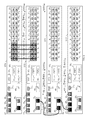
- FIG. 5 is a block diagram that illustrates the relevant fields of a ‘hello’ message 500 , an ‘authentication request’ message 510 , an ‘authentication response’ message 520 , an ‘authentication successful’ message 530 , and an ‘authentication failed’ message 540 , in accordance with one embodiment of the present invention.
- Each ‘hello’ message 500 includes a message-type field 501 , a session-id field 502 , a unit-id field 503 , a protocol revision field 504 and a maximum stack size field 505 .
- the message-type field 501 identifies the associated message as a ‘hello’ message.
- the purpose of the ‘hello’ message is to request information from the neighboring stackable device.
- the session-id field 502 identifies the discovery process currently being implemented.
- the unit-id field 503 includes an ID value that identifies the stackable device that originates the ‘hello’ message (i.e., stackable device ST 1 ).
- the unit-id field 503 of the ‘hello’ messages HEL 1U and HEL 1D will identify stackable device ST 1 .
- This unit-id field 503 may include, for example, the MAC address of stackable device ST 1 .
- the protocol revision field 504 includes information that identifies the current revision of the control protocol being used.
- the maximum stack size field 505 includes a value that identifies the number of times that the ‘hello’ message can be forwarded. In the described examples, the maximum stack size field 505 is initially selected to have a value of ‘7’, such that the corresponding ‘hello’ message can be forwarded up to seven times in either the upstream or downstream direction. The maximum number of stackable devices in the stack is limited to the initial value stored in the maximum stack size field 505 , plus one.
- the ‘hello’ message HEL 1U transmitted on stacking port 25 1 reaches the stacking port 26 2 of stackable device ST 2 at 1 hop via stacking link SL 12 .
- the ‘hello’ message HEL 1D transmitted on stacking port 26 1 reaches the stacking port 27 3 of stackable device ST 3 at 1 hop via stacking link SL 13 .
- stackable device ST 2 Upon receiving the ‘hello’ message HEL 1U on stacking port SP 2D , stackable device ST 2 determines whether its associated protocol revision information matches the protocol revision information included in the protocol revision field 504 of the received ‘hello’ message HEL 1U . Stackable device ST 2 may decide to discontinue the discovery process if a match is not detected. In this case, stackable device ST 2 will not forward the received ‘hello’ message HEL 1U , thereby preventing the discovery of upstream stackable devices through stackable device ST 2 . Stackable device ST 3 performs similar operations in response to the ‘hello’ message HEL 1D received on stacking port 27 3 . The protocol revision information ensures that all members of a stack are configured to implement the same protocol. In the described examples, it is assumed that all of the stackable devices ST 1 -ST 4 implement the same protocol revision.
- stackable device ST 2 upon receiving the ‘hello’ message HEL 1U on stacking port 26 2 , stackable device ST 2 initiates an authentication process, wherein stackable device ST 2 determines whether the stackable device ST 1 that transmitted the ‘hello’ message HEL 1U is an authentic device (i.e., a stackable device that should be allowed to join a stack that includes stackable device ST 2 ). Similarly, upon receiving the ‘hello’ message HEL 1D on stacking port 27 3 , stackable device ST 3 initiates an identical authentication process.
- an authentic device i.e., a stackable device that should be allowed to join a stack that includes stackable device ST 2 .
- a stackable device transmits an ‘authentication request’ message to the stacking link on which the corresponding ‘hello’ message was received.
- stackable device ST 2 transmits an ‘authentication request’ message REQ 2D to stackable device ST 1 via stacking link SL 12 .
- stackable device ST 3 transmits an ‘authentication request’ message REQ 3U to stackable device ST 1 via stacking link SL 13 .
- Each ‘authentication request’ message 510 includes a message-type field 511 and a key field 512 ( FIG. 5 ).
- the message-type field 511 stores a value that identifies the associated message as an ‘authentication request’ message.
- the key field 512 stores a key value that is to be decoded by the stackable device receiving the ‘authentication request’ message.
- ‘authentication request’ message REQ 2D includes a first key value KEY 1
- ‘authentication request’ message REQ 3U includes a second key value KEY 2 .
- a stackable device In response to receiving an ‘authentication request’ message, a stackable device will generate a decoded key value in response to the key value included in the ‘authentication request’ message.
- stackable device ST 1 generates a first decoded key value DKEY 1 in response to the key value KEY 1 included in the received ‘authentication request’ message REQ 2D .
- Stackable device ST 1 also generates a second decoded key value DKEY 2 in response to the key value KEY 2 included in the received ‘authentication request’ message REQ 3U .
- Stackable device ST 1 then returns the decoded key values to the stackable devices that originated the ‘authentication request’ messages. More specifically, stackable device ST 1 generates ‘authentication response’ messages RES 1U and RES 1D , which are transmitted to stackable devices ST 2 and ST 3 , respectively.
- Each ‘authentication response’ message 220 includes message-type field 521 , key field 522 and key-decode field 523 ( FIG. 5 ).
- the message-type field 521 stores a value that identifies the associated message as an ‘authentication response’ message.
- the key field 522 stores the key value that was originally received in the corresponding ‘authentication request’ message.
- the key-decode field 523 includes the decoded key value that was generated in response to the key value of key field 522 .
- stackable device ST 1 provides an ‘authentication response’ message RES 1U to stackable device ST 2 , wherein this message RES 1U includes the key value KEY 1 of the ‘authentication request’ message REQ 2D and the corresponding decoded key value DKEY 1 .
- Stackable device ST 1 also provides an ‘authentication response message RES 1D to stackable device ST 3 , wherein this message RES 1D includes the key value KEY 2 of the ‘authentication request’ message REQ 3U and the corresponding decoded key value DKEY 2 .
- a stackable device Upon receiving an ‘authentication response’ message, a stackable device will determine whether the authentication process was a success or a failure. To accomplish this, the stackable device receiving the ‘authentication response’ message independently generates a decoded key value in response to the original key value. For example, upon receiving the authentication response message RES 1U , stackable device ST 2 independently generates a decoded key value DKEY 1 ′ in response to the original key value KEY 1 . If this independently generated decoded key value DKEY 1 ′ matches the decoded key value DKEY 1 included in the ‘authentication response’ message RES 1U , then the authentication process is successful. Otherwise, the authentication process has failed.
- both stackable devices must implement the same key decoding algorithm in order for the authentication process to be successful. Unauthorized stackable devices will not implement the same key decoding algorithms as authentic stackable devices, thereby preventing the authentication of unauthorized stackable devices. In this manner, the authentication process prevents a malicious device from joining the stack, thereby providing security to the user.
- a stackable device determines that the authentication process has failed because the decoded key values do not match, then this stackable device returns an ‘authentication failed’ message to the neighboring stackable device from which the ‘hello’ message was received. For example, upon determining that the authentication process has failed, stackable device ST 2 will transmit an ‘authentication failed’ message FAIL 2D to stackable device ST 1 . Similarly, upon determining that the authentication process has failed, stackable device ST 3 will transmit an ‘authentication failed’ message FAIL 3U to stackable device ST 1 .
- Each ‘authentication failed’ message 540 includes a message-type field 541 , which indicates that the authentication process was unsuccessful.
- stackable device ST 1 In response to receiving the FAIL 2D message or the FAIL 3U message, stackable device ST 1 will not allow the corresponding stackable device ST 2 or ST 3 to join the stack (or will remove the corresponding stackable device ST 2 or ST 3 from the existing stack). In addition, if the authentication process has failed within a stackable device, then this stackable device will not forward the received ‘hello’ message. For example, if authentication fails within stackable device ST 2 , then stackable device ST 2 will not forward the received ‘hello’ message HEL 1U on its upstream stacking port 1 2 - 8 2 , thereby preventing the discovery of upstream stackable device ST 4 through stackable device ST 2 . However, in the described examples, it is assumed that the authentication process is successful in both of stackable devices ST 2 and ST 3 . Note the authentication process should be successful in stackable devices ST 2 and ST 3 because as these stackable devices are original members of the stack 200 .
- a stackable device that determines that the authentication process was successful returns an ‘authentication successful’ message to the neighboring stackable device from which the ‘hello’ message was received. For example, upon determining that the authentication process was successful, stackable devices ST 2 and ST 3 transmit ‘authentication successful’ messages SUCC 2D and SUCC 3U , respectively, to stackable device ST 1 .
- the successful authentication of a stackable device will expire after a predetermined period (e.g. 1 minute) of inactivity.
- a predetermined period e.g. 1 minute
- the ‘authentication successful’ message must be sent before the predetermined period expires.
- Each ‘authentication successful’ message 530 includes message-type field 531 , hop-count field 532 , unit-type field 533 , priority field 534 , security type field 535 , security information field 536 and unit-id field 537 ( FIG. 5 ).
- the message-type field 531 stores a value that identifies the associated message as an ‘authentication successful’ message.
- the hop count field 532 indicates the number of hops that the ‘authentication successful’ message has traveled.
- the stackable device that originally generates the ‘authentication successful’ message sets the hop count field 532 to a value of ‘1’.
- the hop count field 532 will have a value of ‘1’. If a stackable device that is not the active controller receives an ‘authentication successful’ message on one of its stacking ports, this stackable device will add ‘1’ to the value stored in the hop count field 532 , and then forward the modified ‘authentication successful’ message to its other stacking port.
- the hop count field 532 indicates the number of hops that exist between the stackable device that originated the ‘authentication successful’ message and the active controller.
- the value stored in the hop count field 532 is limited to the value initially stored in the maximum stack size field 505 of ‘hello’ message 500 . (e.g., 7).
- the unit type field 533 includes information that identifies the type (e.g., model number) of the stackable device that originally generates the ‘authentication successful’ message. Note that the stack 200 may support multiple different unit types.
- the priority field 534 includes a priority value that specifies an assigned priority of the stackable device that originally generates the ‘authentication successful’ message 530 .
- the stackable devices ST 2 and ST 3 have assigned priority value lower than the assigned priority value of stackable device ST 1 .
- the security type field 535 and the security information field 536 support further authentication, which may be required by stackable devices other than the active controller.
- the security type field 535 identifies a ‘type’ of security information included in the security information field 536 .
- the security information field 536 includes the actual security information required to access the stackable device that originates the ‘authentication successful’ message.
- the security type field 535 of ‘authentication successful’ message SUCC 2D may indicate that a password is required in order to access stackable device ST 2 .
- the security information field 536 of ‘authentication successful’ message SUCC 2D includes the (encrypted) password required to access stackable device ST 2 .
- stackable device ST 1 decrypts the encrypted password.
- the password is entered via a user console connected to port 31 1 of the stackable device ST 1 .
- stackable device ST 1 allows the password-protected stackable device ST 2 to join in the stack 200 .
- stackable device ST 1 stores the correct password in memory 50 1 , such that a user only has to enter the required password once.
- stackable device ST 1 receives ‘authentication successful’ messages after the initial configuration of the stack 200 , stackable device ST 1 compares the previously stored correct password with the contents of the security information field 536 of these ‘authentication successful’ messages.
- the unit-id field 537 includes a value, such as a MAC address, that identifies the stackable device that originates the ‘authentication successful’ message.
- a value such as a MAC address
- the stackable device ST 1 active controller
- stores the associated information i.e., hop-count, unit-type, priority, security type, security info and unit-id
- Stackable device ST 1 monitors any changes to the connectivity database to determine if there are have been changes to the topology of the stack 200 .
- a stackable device If a stackable device generates an ‘authentication successful’ message in response to a ‘hello’ message received on a first stacking port of the stackable device, then this stackable device will determine whether the value stored in the maximum stack size field 205 of this received ‘hello message’ has a positive value. If so, then this stackable device will decrement the value stored in the maximum stack size field 505 of this ‘hello’ message by one, and forward the modified ‘hello’ message onto the second stacking port of the stackable device.
- stackable device ST 2 determines that the value stored in the maximum stack size field 505 of the received ‘hello’ message HEL 1U has a positive value (i.e., ‘7’). In response, stackable device ST 2 decrements this value by one, such that the maximum stack size field 505 of the ‘hello’ message HEL 1U stores a value of ‘6’. Stackable device then forwards this modified ‘hello’ message HEL 1U to stackable device ST 4 (via stacking port 1 2 - 8 2 , stacking link SL 24 and stacking port 1 4 - 8 4 ).
- stackable device ST 4 initiates the authentication process described above, wherein stackable device ST 4 transmits an ‘authentication request’ message REQ 4D to stackable device ST 2 , stackable device ST 2 returns an ‘authentication response’ message RES 2U to stackable device ST 4 , and stackable device ST 4 determines whether the authentication process was successful or failed. If the authentication is successful (and stackable device ST 4 is not already a member of another stack), stackable device ST 4 generates an ‘authentication successful’ message SUCC 4D in the manner described above. This ‘authentication successful’ message is transmitted to stackable device ST 2 (via stacking port 1 4 - 8 4 , stacking link SL 24 and stacking port 1 2 - 8 2 ).
- Stackable device ST 2 adds ‘1’ to the hop count field 532 of this ‘authentication successful’ message SUCC 4D , such that this hop count field 532 is modified to have a value of ‘2’. Stackable device ST 2 then transmits the modified ‘authentication successful’ message SUCC 4D to stackable device ST 1 (via stacking port 26 2 , stacking link SL 12 and stacking port 25 1 ). Note that the ‘authentication successful’ message received by stackable device ST 1 properly indicates that stackable device ST 4 is 2 hops from stackable device ST 1 in the upstream direction.
- stackable device ST 4 If the authentication fails, then stackable device ST 4 generates an ‘authentication failed’ message FAIL 4D in the manner described above. This ‘authentication failed’ message is transmitted to stackable device ST 2 (via stacking port 1 4 - 8 4 , stacking link SL 24 and stacking port 1 2 - 8 2 ). In response, stackable device ST 2 does not allow stackable device ST 4 to join the stack 200 via stacking link SL 24 . That is, stackable device ST 2 does forward any information about stackable device ST 4 to stackable device ST 1 . In the manner described above, the authentication process is performed between two neighboring stackable devices, and therefore does not always require the participation of the active controller.
- the maximum stack size field 505 of this ‘hello’ message will have a value of ‘0’. If a stackable device receives a ‘hello’ message with a maximum stack size field 505 having a value of ‘0’, this stackable device will neither respond to nor forward this ‘hello’ message, because it is not possible that any stackable device receiving the ‘hello’ message could be added to the stack without exceeding the maximum stack size.
- the maximum number of stackable devices e.g., 8) are connected in a ring topology, then the stackable device ST 1 will receive ‘hello’ messages HEL 1U and HEL 1D having maximum stack size fields 505 that store values of ‘0’. In this case, the stackable device ST 1 may use these received ‘hello’ messages HEL 1U and HEL 1D to determine that the stack is connected in a ring topology.
- stackable device ST 1 Upon receiving the ‘authentication successful’ message SUCC 4D from the newly connected stackable device ST 4 , stackable device ST 1 determines whether this ‘authentication successful’ message includes entries in the security type field 535 and the security information field 536 that require the entry of a password. If so, stackable device ST 1 will prompt the user to enter the required security information. Upon receiving (and storing) the required security information, stackable device ST 1 stores the information included in ‘authentication successful’ message SUCC 4D in the connectivity database. Stackable device ST 1 determines that the identifying information associated with stackable device ST 4 was not previously stored in the connectivity database.
- stackable device ST 1 dynamically determines whether this stackable device ST 4 can join the stack 200 , based on the contents of the connectivity database and the limitations of maximum stack size (i.e., based on the configuration of the stack). If the stackable device ST 1 determines that the newly detected stackable device ST 4 can join the stack 200 , then stackable device ST 1 issues ‘stack port’ instructions that cause flexible stacking ports 1 2 - 8 2 and 1 4 - 8 4 to be configured as actual stacking ports.
- stackable device ST 1 issues a first ‘stack-port’ instruction (on stacking port 25 1 ) that includes a unit-id field 302 that identifies stackable device ST 2 , and a stacking port id field 303 that identifies flexible stacking port 1 2 - 8 2 .
- stackable device ST 2 configures flexible stacking port 1 2 - 8 2 as an actual stacking port.
- Stackable device ST 1 also issues a second ‘stack-port’ instruction (on stacking port 25 1 ) that includes a unit-id field 302 that identifies stackable device ST 4 , and a stacking port id field 303 that identifies flexible stacking port 1 4 - 8 4 , such that flexible stacking port 1 4 - 8 4 is also configured as an actual stacking port. If the stackable device ST 1 determines that the new stackable device ST 4 cannot join the stack 200 , then the flexible stacking ports 1 2 - 8 2 and 1 4 - 8 4 can still function as regular data ports.
Abstract
Description
Claims (18)
Priority Applications (1)
| Application Number | Priority Date | Filing Date | Title |
|---|---|---|---|
| US13/850,118 US9282058B2 (en) | 2009-05-11 | 2013-03-25 | Flexible stacking port |
Applications Claiming Priority (2)
| Application Number | Priority Date | Filing Date | Title |
|---|---|---|---|
| US12/463,964 US9282057B2 (en) | 2009-05-11 | 2009-05-11 | Flexible stacking port |
| US13/850,118 US9282058B2 (en) | 2009-05-11 | 2013-03-25 | Flexible stacking port |
Related Parent Applications (1)
| Application Number | Title | Priority Date | Filing Date |
|---|---|---|---|
| US12/463,964 Continuation US9282057B2 (en) | 2009-05-11 | 2009-05-11 | Flexible stacking port |
Publications (2)
| Publication Number | Publication Date |
|---|---|
| US20130215791A1 US20130215791A1 (en) | 2013-08-22 |
| US9282058B2 true US9282058B2 (en) | 2016-03-08 |
Family
ID=43062296
Family Applications (2)
| Application Number | Title | Priority Date | Filing Date |
|---|---|---|---|
| US12/463,964 Expired - Fee Related US9282057B2 (en) | 2009-05-11 | 2009-05-11 | Flexible stacking port |
| US13/850,118 Active 2029-11-04 US9282058B2 (en) | 2009-05-11 | 2013-03-25 | Flexible stacking port |
Family Applications Before (1)
| Application Number | Title | Priority Date | Filing Date |
|---|---|---|---|
| US12/463,964 Expired - Fee Related US9282057B2 (en) | 2009-05-11 | 2009-05-11 | Flexible stacking port |
Country Status (1)
| Country | Link |
|---|---|
| US (2) | US9282057B2 (en) |
Cited By (10)
| Publication number | Priority date | Publication date | Assignee | Title |
|---|---|---|---|---|
| US20160246618A1 (en) * | 2015-02-20 | 2016-08-25 | Dell Products L.P. | Automatic discovery and configuration of stack ports |
| US9559897B2 (en) | 2012-12-21 | 2017-01-31 | Brocade Communications Systems, Inc. | Device ID assignment in a system of devices |
| US9577932B2 (en) | 2014-02-12 | 2017-02-21 | Brocade Communications Systems, Inc. | Techniques for managing ternary content-addressable memory (TCAM) resources in heterogeneous systems |
| US9660937B2 (en) | 2013-10-31 | 2017-05-23 | Brocade Communications Systems, Inc. | Techniques for simplifying stacking trunk creation and management |
| US9692652B2 (en) | 2014-04-03 | 2017-06-27 | Brocade Communications Systems, Inc. | Framework for reliably communicating port information in a system of devices |
| US9692695B2 (en) | 2014-03-27 | 2017-06-27 | Brocade Communications Systems, Inc. | Techniques for aggregating hardware routing resources in a multi-packet processor networking system |
| US9853889B2 (en) | 2013-05-20 | 2017-12-26 | Brocade Communications Systems, Inc. | Broadcast and multicast traffic reduction in stacking systems |
| US9860133B2 (en) | 2013-05-20 | 2018-01-02 | Brocade Communications Systems, Inc. | Configuration validation in a mixed node topology |
| US10091059B2 (en) | 2014-12-16 | 2018-10-02 | Arris Enterprises Llc | Handling connections between network devices that support multiple port communication modes |
| US10284499B2 (en) | 2013-08-22 | 2019-05-07 | Arris Enterprises Llc | Dedicated control path architecture for systems of devices |
Families Citing this family (69)
| Publication number | Priority date | Publication date | Assignee | Title |
|---|---|---|---|---|
| JP5349816B2 (en) * | 2008-03-18 | 2013-11-20 | 富士通株式会社 | Line monitoring apparatus and line monitoring method |
| US9270486B2 (en) | 2010-06-07 | 2016-02-23 | Brocade Communications Systems, Inc. | Name services for virtual cluster switching |
| US8989186B2 (en) | 2010-06-08 | 2015-03-24 | Brocade Communication Systems, Inc. | Virtual port grouping for virtual cluster switching |
| US9001824B2 (en) | 2010-05-18 | 2015-04-07 | Brocade Communication Systems, Inc. | Fabric formation for virtual cluster switching |
| US9461840B2 (en) | 2010-06-02 | 2016-10-04 | Brocade Communications Systems, Inc. | Port profile management for virtual cluster switching |
| US8867552B2 (en) | 2010-05-03 | 2014-10-21 | Brocade Communications Systems, Inc. | Virtual cluster switching |
| US9716672B2 (en) | 2010-05-28 | 2017-07-25 | Brocade Communications Systems, Inc. | Distributed configuration management for virtual cluster switching |
| US9628293B2 (en) | 2010-06-08 | 2017-04-18 | Brocade Communications Systems, Inc. | Network layer multicasting in trill networks |
| US9246703B2 (en) | 2010-06-08 | 2016-01-26 | Brocade Communications Systems, Inc. | Remote port mirroring |
| US9608833B2 (en) | 2010-06-08 | 2017-03-28 | Brocade Communications Systems, Inc. | Supporting multiple multicast trees in trill networks |
| US9807031B2 (en) | 2010-07-16 | 2017-10-31 | Brocade Communications Systems, Inc. | System and method for network configuration |
| CN102171976B (en) * | 2011-04-14 | 2013-09-11 | 华为技术有限公司 | Data transmission method on switch device and apparatus thereof |
| US9270572B2 (en) | 2011-05-02 | 2016-02-23 | Brocade Communications Systems Inc. | Layer-3 support in TRILL networks |
| US8948056B2 (en) | 2011-06-28 | 2015-02-03 | Brocade Communication Systems, Inc. | Spanning-tree based loop detection for an ethernet fabric switch |
| US9401861B2 (en) | 2011-06-28 | 2016-07-26 | Brocade Communications Systems, Inc. | Scalable MAC address distribution in an Ethernet fabric switch |
| US9407533B2 (en) | 2011-06-28 | 2016-08-02 | Brocade Communications Systems, Inc. | Multicast in a trill network |
| US8885641B2 (en) | 2011-06-30 | 2014-11-11 | Brocade Communication Systems, Inc. | Efficient trill forwarding |
| US9762434B2 (en) * | 2011-08-12 | 2017-09-12 | Rambus Inc. | Temporal redundancy |
| US9736085B2 (en) | 2011-08-29 | 2017-08-15 | Brocade Communications Systems, Inc. | End-to end lossless Ethernet in Ethernet fabric |
| US9699117B2 (en) | 2011-11-08 | 2017-07-04 | Brocade Communications Systems, Inc. | Integrated fibre channel support in an ethernet fabric switch |
| US9450870B2 (en) | 2011-11-10 | 2016-09-20 | Brocade Communications Systems, Inc. | System and method for flow management in software-defined networks |
| US8665704B2 (en) * | 2011-11-25 | 2014-03-04 | Hewlett-Packard Development Company, L.P. | Parallelly coupled stackable network switching device |
| US8995272B2 (en) | 2012-01-26 | 2015-03-31 | Brocade Communication Systems, Inc. | Link aggregation in software-defined networks |
| US9742693B2 (en) | 2012-02-27 | 2017-08-22 | Brocade Communications Systems, Inc. | Dynamic service insertion in a fabric switch |
| CN104205943B (en) * | 2012-03-05 | 2018-03-09 | 富士通株式会社 | Communication system and communication means |
| US9154416B2 (en) | 2012-03-22 | 2015-10-06 | Brocade Communications Systems, Inc. | Overlay tunnel in a fabric switch |
| US9374301B2 (en) | 2012-05-18 | 2016-06-21 | Brocade Communications Systems, Inc. | Network feedback in software-defined networks |
| US10277464B2 (en) | 2012-05-22 | 2019-04-30 | Arris Enterprises Llc | Client auto-configuration in a multi-switch link aggregation |
| EP2853066B1 (en) | 2012-05-23 | 2017-02-22 | Brocade Communications Systems, Inc. | Layer-3 overlay gateways |
| US9602430B2 (en) | 2012-08-21 | 2017-03-21 | Brocade Communications Systems, Inc. | Global VLANs for fabric switches |
| US9401872B2 (en) | 2012-11-16 | 2016-07-26 | Brocade Communications Systems, Inc. | Virtual link aggregations across multiple fabric switches |
| US9548926B2 (en) | 2013-01-11 | 2017-01-17 | Brocade Communications Systems, Inc. | Multicast traffic load balancing over virtual link aggregation |
| US9350680B2 (en) | 2013-01-11 | 2016-05-24 | Brocade Communications Systems, Inc. | Protection switching over a virtual link aggregation |
| US9413691B2 (en) | 2013-01-11 | 2016-08-09 | Brocade Communications Systems, Inc. | MAC address synchronization in a fabric switch |
| US9565113B2 (en) | 2013-01-15 | 2017-02-07 | Brocade Communications Systems, Inc. | Adaptive link aggregation and virtual link aggregation |
| CN103944838B (en) * | 2013-01-22 | 2017-07-14 | 新华三技术有限公司 | Pile system and its implementation |
| US9565099B2 (en) | 2013-03-01 | 2017-02-07 | Brocade Communications Systems, Inc. | Spanning tree in fabric switches |
| US9401818B2 (en) | 2013-03-15 | 2016-07-26 | Brocade Communications Systems, Inc. | Scalable gateways for a fabric switch |
| US9148387B2 (en) | 2013-05-10 | 2015-09-29 | Brocade Communications Systems, Inc. | Hardware hash table virtualization in multi-packet processor networking systems |
| US9699001B2 (en) | 2013-06-10 | 2017-07-04 | Brocade Communications Systems, Inc. | Scalable and segregated network virtualization |
| US9565028B2 (en) | 2013-06-10 | 2017-02-07 | Brocade Communications Systems, Inc. | Ingress switch multicast distribution in a fabric switch |
| US9503322B2 (en) * | 2013-07-31 | 2016-11-22 | Dell Products L.P. | Automatic stack unit replacement system |
| US9806949B2 (en) | 2013-09-06 | 2017-10-31 | Brocade Communications Systems, Inc. | Transparent interconnection of Ethernet fabric switches |
| US9912612B2 (en) | 2013-10-28 | 2018-03-06 | Brocade Communications Systems LLC | Extended ethernet fabric switches |
| US9548873B2 (en) | 2014-02-10 | 2017-01-17 | Brocade Communications Systems, Inc. | Virtual extensible LAN tunnel keepalives |
| US10581758B2 (en) | 2014-03-19 | 2020-03-03 | Avago Technologies International Sales Pte. Limited | Distributed hot standby links for vLAG |
| US10476698B2 (en) | 2014-03-20 | 2019-11-12 | Avago Technologies International Sales Pte. Limited | Redundent virtual link aggregation group |
| CN103856357B (en) * | 2014-03-21 | 2019-03-26 | 迈普通信技术股份有限公司 | A kind of stacking system fault handling method and stacking system |
| US10063473B2 (en) | 2014-04-30 | 2018-08-28 | Brocade Communications Systems LLC | Method and system for facilitating switch virtualization in a network of interconnected switches |
| US9800471B2 (en) | 2014-05-13 | 2017-10-24 | Brocade Communications Systems, Inc. | Network extension groups of global VLANs in a fabric switch |
| US10616108B2 (en) | 2014-07-29 | 2020-04-07 | Avago Technologies International Sales Pte. Limited | Scalable MAC address virtualization |
| US9544219B2 (en) | 2014-07-31 | 2017-01-10 | Brocade Communications Systems, Inc. | Global VLAN services |
| US9807007B2 (en) | 2014-08-11 | 2017-10-31 | Brocade Communications Systems, Inc. | Progressive MAC address learning |
| US9524173B2 (en) | 2014-10-09 | 2016-12-20 | Brocade Communications Systems, Inc. | Fast reboot for a switch |
| US9699029B2 (en) | 2014-10-10 | 2017-07-04 | Brocade Communications Systems, Inc. | Distributed configuration management in a switch group |
| US9912544B2 (en) * | 2014-10-28 | 2018-03-06 | Dell Products L.P. | System and method for master switch election |
| US9628407B2 (en) | 2014-12-31 | 2017-04-18 | Brocade Communications Systems, Inc. | Multiple software versions in a switch group |
| US9626255B2 (en) | 2014-12-31 | 2017-04-18 | Brocade Communications Systems, Inc. | Online restoration of a switch snapshot |
| US10003552B2 (en) | 2015-01-05 | 2018-06-19 | Brocade Communications Systems, Llc. | Distributed bidirectional forwarding detection protocol (D-BFD) for cluster of interconnected switches |
| US9942097B2 (en) | 2015-01-05 | 2018-04-10 | Brocade Communications Systems LLC | Power management in a network of interconnected switches |
| US9807005B2 (en) | 2015-03-17 | 2017-10-31 | Brocade Communications Systems, Inc. | Multi-fabric manager |
| US10038592B2 (en) | 2015-03-17 | 2018-07-31 | Brocade Communications Systems LLC | Identifier assignment to a new switch in a switch group |
| US10579406B2 (en) | 2015-04-08 | 2020-03-03 | Avago Technologies International Sales Pte. Limited | Dynamic orchestration of overlay tunnels |
| CN106161288B (en) * | 2015-04-17 | 2019-08-16 | 新华三技术有限公司 | Realize the method and apparatus that multiple devices stack |
| US10439929B2 (en) | 2015-07-31 | 2019-10-08 | Avago Technologies International Sales Pte. Limited | Graceful recovery of a multicast-enabled switch |
| US10171303B2 (en) | 2015-09-16 | 2019-01-01 | Avago Technologies International Sales Pte. Limited | IP-based interconnection of switches with a logical chassis |
| US9912614B2 (en) | 2015-12-07 | 2018-03-06 | Brocade Communications Systems LLC | Interconnection of switches based on hierarchical overlay tunneling |
| US11032684B2 (en) * | 2016-06-27 | 2021-06-08 | Intel Corporation | Autonomous sharing of data between geographically proximate nodes |
| US20210211351A1 (en) * | 2020-01-07 | 2021-07-08 | Arris Enterprises Llc | Stacking-port configuration using zero-touch provisioning |
Citations (9)
| Publication number | Priority date | Publication date | Assignee | Title |
|---|---|---|---|---|
| US20060023640A1 (en) * | 2004-07-29 | 2006-02-02 | Zarlink Semiconductor Inc. | Remote control of a switching node in a stack of switching nodes |
| US20060072571A1 (en) | 2004-09-29 | 2006-04-06 | Navada Muraleedhara H | Integrated circuit capable of routing multicast data packets using device vectors |
| US20060092853A1 (en) * | 2004-10-28 | 2006-05-04 | Ignatius Santoso | Stack manager protocol with automatic set up mechanism |
| US20060187900A1 (en) * | 2005-02-22 | 2006-08-24 | Akbar Imran M | Method and system for providing private virtual secure Voice over Internet Protocol communications |
| US20060253557A1 (en) * | 2005-05-06 | 2006-11-09 | Broadcom Corporation | Stacking into BCMX |
| US7274694B1 (en) * | 2003-01-09 | 2007-09-25 | Cisco Technology, Inc. | Defining link aggregation across a stack |
| US7480258B1 (en) | 2003-07-03 | 2009-01-20 | Cisco Technology, Inc. | Cross stack rapid transition protocol |
| US7523227B1 (en) | 2003-01-14 | 2009-04-21 | Cisco Technology, Inc. | Interchangeable standard port or stack port |
| US20100172365A1 (en) * | 2005-04-06 | 2010-07-08 | Broadcom Corporation | HiGig AUTOTRUNKING |
-
2009
- 2009-05-11 US US12/463,964 patent/US9282057B2/en not_active Expired - Fee Related
-
2013
- 2013-03-25 US US13/850,118 patent/US9282058B2/en active Active
Patent Citations (9)
| Publication number | Priority date | Publication date | Assignee | Title |
|---|---|---|---|---|
| US7274694B1 (en) * | 2003-01-09 | 2007-09-25 | Cisco Technology, Inc. | Defining link aggregation across a stack |
| US7523227B1 (en) | 2003-01-14 | 2009-04-21 | Cisco Technology, Inc. | Interchangeable standard port or stack port |
| US7480258B1 (en) | 2003-07-03 | 2009-01-20 | Cisco Technology, Inc. | Cross stack rapid transition protocol |
| US20060023640A1 (en) * | 2004-07-29 | 2006-02-02 | Zarlink Semiconductor Inc. | Remote control of a switching node in a stack of switching nodes |
| US20060072571A1 (en) | 2004-09-29 | 2006-04-06 | Navada Muraleedhara H | Integrated circuit capable of routing multicast data packets using device vectors |
| US20060092853A1 (en) * | 2004-10-28 | 2006-05-04 | Ignatius Santoso | Stack manager protocol with automatic set up mechanism |
| US20060187900A1 (en) * | 2005-02-22 | 2006-08-24 | Akbar Imran M | Method and system for providing private virtual secure Voice over Internet Protocol communications |
| US20100172365A1 (en) * | 2005-04-06 | 2010-07-08 | Broadcom Corporation | HiGig AUTOTRUNKING |
| US20060253557A1 (en) * | 2005-05-06 | 2006-11-09 | Broadcom Corporation | Stacking into BCMX |
Non-Patent Citations (6)
| Title |
|---|
| Appeal Brief Dated Jan. 18, 2013; U.S. Appl. No. 12/463,964 (23 p.). |
| Examiner's Answer Dated May 7, 2013; U.S. Appl. No. 12/463,964 (12 p.). |
| Final Office Action Dated Jan. 23, 2012; U.S. Appl. No. 12/463,964 (11 p.). |
| Office Action Dated Mar. 21, 2011; U.S. Appl. No. 12/463,964 (10 p.). |
| Reply Brief Dated Jul. 8, 2013; U.S. Appl. No. 12/463,964 (14 p.). |
| Response to Office Action Dated Mar. 21, 2011; U.S. Appl. No. 12/463,964; Response Filed Sep. 21, 2011 (12 p.). |
Cited By (11)
| Publication number | Priority date | Publication date | Assignee | Title |
|---|---|---|---|---|
| US9559897B2 (en) | 2012-12-21 | 2017-01-31 | Brocade Communications Systems, Inc. | Device ID assignment in a system of devices |
| US9853889B2 (en) | 2013-05-20 | 2017-12-26 | Brocade Communications Systems, Inc. | Broadcast and multicast traffic reduction in stacking systems |
| US9860133B2 (en) | 2013-05-20 | 2018-01-02 | Brocade Communications Systems, Inc. | Configuration validation in a mixed node topology |
| US10284499B2 (en) | 2013-08-22 | 2019-05-07 | Arris Enterprises Llc | Dedicated control path architecture for systems of devices |
| US9660937B2 (en) | 2013-10-31 | 2017-05-23 | Brocade Communications Systems, Inc. | Techniques for simplifying stacking trunk creation and management |
| US9577932B2 (en) | 2014-02-12 | 2017-02-21 | Brocade Communications Systems, Inc. | Techniques for managing ternary content-addressable memory (TCAM) resources in heterogeneous systems |
| US9692695B2 (en) | 2014-03-27 | 2017-06-27 | Brocade Communications Systems, Inc. | Techniques for aggregating hardware routing resources in a multi-packet processor networking system |
| US9692652B2 (en) | 2014-04-03 | 2017-06-27 | Brocade Communications Systems, Inc. | Framework for reliably communicating port information in a system of devices |
| US10091059B2 (en) | 2014-12-16 | 2018-10-02 | Arris Enterprises Llc | Handling connections between network devices that support multiple port communication modes |
| US20160246618A1 (en) * | 2015-02-20 | 2016-08-25 | Dell Products L.P. | Automatic discovery and configuration of stack ports |
| US9961043B2 (en) * | 2015-02-20 | 2018-05-01 | Dell Products L.P. | Automatic discovery and configuration of stack ports |
Also Published As
| Publication number | Publication date |
|---|---|
| US20130215791A1 (en) | 2013-08-22 |
| US20100284414A1 (en) | 2010-11-11 |
| US9282057B2 (en) | 2016-03-08 |
Similar Documents
| Publication | Publication Date | Title |
|---|---|---|
| US9282058B2 (en) | Flexible stacking port | |
| US9294350B2 (en) | Secure stacking setup | |
| EP1782580B1 (en) | Method and apparatus for detecting support for a protocol defining supplemental headers | |
| CN111865779B (en) | Route synchronization method and cross-device link aggregation group | |
| US7978595B2 (en) | Method for processing multiple active devices in stacking system and stacking member device | |
| US8670349B2 (en) | System and method for floating port configuration | |
| US9397747B2 (en) | Method and apparatus for connectivity control in a data center network | |
| EP1742430A1 (en) | Router redundancy in data communication networks | |
| CN104506513B (en) | Fire wall flow table backup method, fire wall and firewall system | |
| US9479484B2 (en) | Mechanism for co-ordinated authentication key transition for IS-IS protocol | |
| AU2004305790A1 (en) | Virtual network device | |
| US20080155157A1 (en) | Hot-swappable multi-configuration modular network service system | |
| CN105340230A (en) | Virtual chassis topology management | |
| JP2005354362A (en) | Network repeater and its controlling method | |
| US20120063299A1 (en) | Highly available virtual packet network device | |
| EP3059910B1 (en) | Method and system for redundancy protection | |
| CN101692654B (en) | Method, system and equipment for HUB-Spoken networking | |
| CN112995027B (en) | Route publishing method and VTEP node | |
| US9596129B2 (en) | Communication system, control apparatus, communication apparatus, information-relaying method, and program | |
| CN102811153A (en) | VLAN state negotiating method and edge device | |
| Cisco | Message and Recovery Procedures | |
| CN112398731B (en) | Method for processing message and first network equipment | |
| CN116055393A (en) | Private line communication method, device and system | |
| CN112751767B (en) | Routing information transmission method and device and data center internet | |
| EP3979570A1 (en) | Method for achieving network communication based on neighbor negotiation and device |
Legal Events
| Date | Code | Title | Description |
|---|---|---|---|
| FEPP | Fee payment procedure |
Free format text: PAYOR NUMBER ASSIGNED (ORIGINAL EVENT CODE: ASPN); ENTITY STATUS OF PATENT OWNER: LARGE ENTITY |
|
| STCF | Information on status: patent grant |
Free format text: PATENTED CASE |
|
| AS | Assignment |
Owner name: BROCADE COMMUNICATIONS SYSTEMS LLC, CALIFORNIA Free format text: CHANGE OF NAME;ASSIGNOR:BROCADE COMMUNICATIONS SYSTEMS, INC.;REEL/FRAME:044861/0618 Effective date: 20171128 |
|
| AS | Assignment |
Owner name: ARRIS ENTERPRISES LLC, GEORGIA Free format text: ASSIGNMENT OF ASSIGNORS INTEREST;ASSIGNORS:BROCADE COMMUNICATIONS SYSTEMS LLC F/K/A BROCADE COMMUNICATIONS SYSTEMS, INC;FOUNDRY NETWORKS LLC F/K/A FOUNDRY NETWORKS INC.;REEL/FRAME:045600/0755 Effective date: 20171201 |
|
| AS | Assignment |
Owner name: WILMINGTON TRUST, NATIONAL ASSOCIATION, AS COLLATE Free format text: PATENT SECURITY AGREEMENT;ASSIGNOR:ARRIS ENTERPRISES LLC;REEL/FRAME:049820/0495 Effective date: 20190404 Owner name: JPMORGAN CHASE BANK, N.A., NEW YORK Free format text: TERM LOAN SECURITY AGREEMENT;ASSIGNORS:COMMSCOPE, INC. OF NORTH CAROLINA;COMMSCOPE TECHNOLOGIES LLC;ARRIS ENTERPRISES LLC;AND OTHERS;REEL/FRAME:049905/0504 Effective date: 20190404 Owner name: JPMORGAN CHASE BANK, N.A., NEW YORK Free format text: ABL SECURITY AGREEMENT;ASSIGNORS:COMMSCOPE, INC. OF NORTH CAROLINA;COMMSCOPE TECHNOLOGIES LLC;ARRIS ENTERPRISES LLC;AND OTHERS;REEL/FRAME:049892/0396 Effective date: 20190404 Owner name: WILMINGTON TRUST, NATIONAL ASSOCIATION, AS COLLATERAL AGENT, CONNECTICUT Free format text: PATENT SECURITY AGREEMENT;ASSIGNOR:ARRIS ENTERPRISES LLC;REEL/FRAME:049820/0495 Effective date: 20190404 |
|
| MAFP | Maintenance fee payment |
Free format text: PAYMENT OF MAINTENANCE FEE, 4TH YEAR, LARGE ENTITY (ORIGINAL EVENT CODE: M1551); ENTITY STATUS OF PATENT OWNER: LARGE ENTITY Year of fee payment: 4 |
|
| AS | Assignment |
Owner name: WILMINGTON TRUST, DELAWARE Free format text: SECURITY INTEREST;ASSIGNORS:ARRIS SOLUTIONS, INC.;ARRIS ENTERPRISES LLC;COMMSCOPE TECHNOLOGIES LLC;AND OTHERS;REEL/FRAME:060752/0001 Effective date: 20211115 |
|
| MAFP | Maintenance fee payment |
Free format text: PAYMENT OF MAINTENANCE FEE, 8TH YEAR, LARGE ENTITY (ORIGINAL EVENT CODE: M1552); ENTITY STATUS OF PATENT OWNER: LARGE ENTITY Year of fee payment: 8 |
|
| AS | Assignment |
Owner name: RUCKUS IP HOLDINGS LLC, NORTH CAROLINA Free format text: ASSIGNMENT OF ASSIGNORS INTEREST;ASSIGNOR:ARRIS ENTERPRISES LLC;REEL/FRAME:066399/0561 Effective date: 20240103 |