US9282041B2 - Congestion profiling of computer network devices - Google Patents
Congestion profiling of computer network devices Download PDFInfo
- Publication number
- US9282041B2 US9282041B2 US13/943,136 US201313943136A US9282041B2 US 9282041 B2 US9282041 B2 US 9282041B2 US 201313943136 A US201313943136 A US 201313943136A US 9282041 B2 US9282041 B2 US 9282041B2
- Authority
- US
- United States
- Prior art keywords
- congestion
- data
- point
- identifier
- profile
- Prior art date
- Legal status (The legal status is an assumption and is not a legal conclusion. Google has not performed a legal analysis and makes no representation as to the accuracy of the status listed.)
- Active, expires
Links
Images


Classifications
-
- H—ELECTRICITY
- H04—ELECTRIC COMMUNICATION TECHNIQUE
- H04L—TRANSMISSION OF DIGITAL INFORMATION, e.g. TELEGRAPHIC COMMUNICATION
- H04L47/00—Traffic control in data switching networks
- H04L47/10—Flow control; Congestion control
- H04L47/11—Identifying congestion
Definitions
- the field of the disclosure relates to computer networks, and more specifically, to computer networks enabled to support the quantized congestion notification (QCN) protocol.
- QCN quantized congestion notification
- Computer systems typically include a combination of computer programs and hardware, such as semiconductors, transistors, chips, circuit boards, storage devices, and processors.
- the computer programs are stored in the storage devices and are executed by the processors.
- Computer systems often send and receive data.
- a computer network is a telecommunications network that allows computer systems to exchange that data.
- a method and computer system for mitigating congestion in a computer network from a source device may include transmitting data frames from a reaction point of a source device.
- the method may also include receiving, at the reaction point, congestion notification messages corresponding to the transmitted data frames and containing congestion feedback data regarding a particular network switching device and an identifier of the particular network switching device.
- the method may also include modifying a congestion profile for the particular network switching device by correlating the identifier of the particular network switching device to a profile entry, and updating the profile entry with the congestion feedback data.
- a method and computer system for mitigating congestion in a computer network at a switching device may include receiving, at a congestion point, data frames from a reaction point of a source device, wherein the data frames contain data regarding the source device and an identifier of the source device.
- the method may also include modifying a congestion profile for the source device by correlating the identifier of the source device to a profile entry, and updating the profile entry with the data.
- FIG. 1 depicts a high-level block diagram representation of a data transmission pathway through a computer network, according to embodiments of the present disclosure.
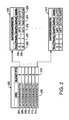
- FIG. 2 depicts block diagram of an example data structure for congestion point profile data, according to embodiments of the present disclosure.
- FIG. 3 depicts a flow chart of example process for modifying congestion point profiles, according to embodiments of the present disclosure.
- FIG. 4 depicts a flow chart of example process for modifying reaction point profiles, according to embodiments of the present disclosure.
- FIG. 5 depicts a high-level block diagram of an exemplary computer system for implementing embodiments of the present disclosure.
- QCN quantized congestion notification
- CNM congestion notification message
- Embodiments of the present disclosure are directed towards a system for mitigating congestion in a computer network.
- This system may include generating congestion profiles for network switching devices that are configured to switch data between source and destination devices.
- the profiles may be generated or updated as congestion notification messages are received from congestion points within the network. These profiles may then be used to proactively control the rate and course of data transmission and thereby, mitigate network congestion.
- FIG. 1 depicts a high-level block diagram representation of a data transmission pathway 100 , according to embodiments of the present disclosure.
- the pathway 100 may represent one possible course through a computer network consisting of any number of end points, such as servers, and switching devices, such as switches, connected in a variety of configurations.
- the pathway 100 may include a source 104 , a reaction point 106 , and a profile database 107 .
- the source 104 , reaction point 106 , and profile database 107 may be located within a single computer system 102 , such as a network server or client.
- the computer system 102 may be considered a source device.
- the pathway may also consist of a network switching devices 110 located within the computer network 112 and communicatively connected to the computer system 102 .
- the device 110 may be a switch, a bridge, or any other network switching device.
- the network 112 may consist of any number of switching devices such as the device 110 communicatively connected to any number of computer systems such as computer system 102 .
- the network 112 may be a local area network (LAN), which can use various communication protocols, such as Ethernet-base protocols.
- the network 112 can be a wide area network (WAN), such as the Internet.
- WAN wide area network
- Embodiments include multiple LANs and/or WANs as part of network 112 .
- the pathway 100 may also include a reflection point 122 and a destination 124 .
- the reflection point 122 and the destination 124 may also be located within a single computer system 120 , such as a server or client.
- the computer system 120 may be considered a destination device.
- the system 120 may also be communicatively connected to the switching device 110 . This connection allows the system 102 and the system 120 to communicate with each other. An example of this communication may include data frames 108 transmitted from the source 104 through the reaction point 106 . The frames 108 pass through the device 110 located within the network 112 . The frames 108 may be received by the reflection point 122 .
- the data frames 108 may include a congestion notification tag to indicate that the reaction point 106 is a quantized congestion notification enabled so as to have the ability to react to congestion notification messages by algorithmically altering the flow rate of data frames 108 .
- the congestion notification tag is not included in the congestion controlled flow frames but the congestion point switches can still react to congestion due to such frames.
- the switching device 110 may be connected to any number of systems, at various times it may experience congestion due to a large amounts of data frames 108 passing through the device 110 . Due to this congestion, the device 110 may also be referred to as a congestion point.
- the device 110 may include one or more queues 114 which serve as buffer where frames 108 may be stored while waiting to pass through the device 110 .
- the device 110 may generate and send a congestion notification message (CNM) 126 back to the reaction point 106 .
- the CNM 126 may include data regarding the congestion.
- An example of congestion data is the quantized congestion notification (QCN) protocol of the Institute of Electrical and Electronics Engineers (IEEE) standard 802.1Qau.
- QCN quantized congestion notification
- IEEE Institute of Electrical and Electronics Engineers
- congestion managed flows of data frames may be restricted to unicast flows where data frames are transmitted with a single specific destination.
- the pathway 100 may serve to generate congestion profiles for network switching devices 100 .
- these switching devices 100 may be configured to switch data between a source 104 and a destination 124 . This operation may begin with the source 104 transmitting data frames 108 from a reaction point 106 . The switching device 100 may then receive the data frames 108 while experience some level of network congestion.
- the device 110 may be considered a congestion point and generate a congestion notification message 126 corresponding to the transmitted data frames 108 , and containing congestion feedback data regarding the congestion experienced at the congestion point 110 and an identifier of the congestion point 110 .
- the switching device may receive the CNM 126 and modify a congestion profile for the congestion point 110 by correlating the identifier to a profile entry, and updating the profile entry with the congestion feedback data.
- FIG. 2 depicts block diagram of an example data structure for congestion point profile data 202 , according to embodiments of the disclosure.
- the profile data 202 may be stored within the profile database 107 of the computer system 102 . Every computer system connected to the network 112 which transmits data frames 108 may contain a profile database 107 which stores profile data 202 .
- the profile data 202 may include records 204 , 206 , 208 , 210 , 212 , and 214 . Each record may represent a congestion point 110 which has returned a CNM 126 to the reaction point 106 .
- Each congestion point 110 may be identified by a congestion point identifier 216 .
- a congestion point identifier 216 may be considered an identifier of a particular network switching device and may be an identifier having a 64 bit value.
- the profile data 202 may also include a bucket pointer 218 for each record.
- the bucket pointer 218 may be a pointer to a congestion point data sub-table 220 .
- Each sub-table 220 may include data contained with each CNM 126 from the respective congestion point 110 .
- the sub-table 220 may include any number of entries such as 224 and 226 . These entries represent a CNM 126 received from the respective congestion point 110 . Each entry may include a time 228 , an encapsulated priority value 230 , a quantized feedback value 232 , a Qoffset value 234 , and a Qdelta value 236 .
- the time 228 may be the time at which the entry was added in the profile table 220 .
- the encapsulated priority value 230 may be a value which represents a data frame's congestion notification priority value which corresponds to IEEE 802.1P bits in the original data frame sent by the reaction point.
- the quantized feedback value 232 , the Qoffset value 234 , and the Qdelta 236 may be values which represent the parameters of the congestion experienced at the congestion point 110 . As previously stated, these values may be calculated using the QCN protocol of the IEEE standard 802.1Qau.
- the congestion point 110 may be configured to store profile data about sources and reaction points. Similar to profile data 202 , the reaction point profile may include data pertaining to various reaction points such as the computer system 102 . The reaction point profile data may use a reaction point identifier in place of the congestion point identifier. A reaction point identifier may be an identifier having a 16 bit value. The reaction point profile would not contain the congestion information of the profile for a congestion point, rather it would include data specific to the reaction point, such as data regarding the data link layer, or layer 2, of the Open Systems Interconnection (OSI) model of computer networking. A result of the collection and analysis of reaction point data is to configure the congestion point 110 to types of data flow as they are received, which is further discussed in FIG. 4 .
- OSI Open Systems Interconnection
- FIG. 3 depicts a flow chart of process 300 for modifying congestion profiles according to embodiments of the present disclosure.
- the process 300 may begin within the computer system 102 .
- the reaction point 106 may transmit data frames 108 .
- the data frames 108 may be received by the congestion point 110 .
- a deciding operation may determine if the congestion point 110 is experiencing congestion. This congestion may be experienced when the congestion point 110 is receiving more data frames 108 than it can transmit. The parameters of the congestion may be determined by referring to the amount of data frames 108 within the queue 114 . If the congestion point 110 is not experiencing congestion, then the process 300 may return to block 306 and the congestion point 110 may continue to receive data frames 108 . If the congestion point 110 is experiencing congestion then the process 300 may proceed to block 312 .
- the congestion may be quantized. As previously stated, the quantization of the congestion may be done using QCN protocol of the IEEE standard 802.1Qau.
- the congestion point 110 may generate a congestion notification message 126 .
- the CNM 126 may include the congestion data from block 312 and a congestion point identifier (CPID) 216 .
- the CNM 126 may be transmitted by the congestion point 110 .
- the CNM 126 may be received by the reaction point 106 of the system 102 .
- the congestion point may use the CPID 216 to correlate the CNM 126 to an entry within the profile data 202 .
- the profile of the congestion point 110 may be modified by updating the congestion point data sub-table 220 corresponding to the congestion point 110 by creating a new entry in the sub-table 220 with the data contained in the CNM 126 . If the profile data 202 does not contain a correlating entry to the CPID 216 , then a new entry may be made with a corresponding sub-table 220 to log the received CNM 126 .
- an analysis of the profile data 202 may be done by the computer system 102 in order to assess the various switching devices of the network 112 .
- the computer system 102 may discover that a particular switch regularly experiences congestion at a particular time of day.
- the computer system 102 may adjust the rate at which it transmits data frames and/or the route in which it transmits data frames based on an analysis of the profile data 202 .
- the result of these adjustments and data frame transmission may have the overall result of mitigating (or completely avoiding) congestion within the network 112 .
- the system 102 may use the analysis from block 324 to adjust how it uses that particular switch.
- the system 102 may determine not to use that switch at all during that particular time of day, it may send low priority data during that time, or it may merely decrease the amount of data it sends though that route at that particular time.
- the system 102 may use a system wide analysis to improve overall network performance by adjusting the rate and routing of its own data transmissions.
- FIG. 4 depicts a flow chart of example process 400 for modifying reaction point profiles, according to embodiments of the present disclosure.
- the process 400 may begin within the computer system 102 .
- the reaction point 106 may transmit data frames 108 .
- the data frames 108 may be received by the congestion point 110 .
- the congestion point may use the reaction point identifier contained in the data frames 108 to correlate the data frames to an entry within reaction point profile data stored in the congestion point 110 .
- the profile of the reaction point 106 may be modified by updating the reaction point data corresponding to the reaction point 106 by creating a new entry with the data contained in the data frames 108 . If the reaction point profile data does not contain a correlating entry to the reaction point 106 , then a new entry may be made with a corresponding sub-table to log the received information.
- an analysis of the reaction point profile data may be done by the congestion point 110 .
- the congestion point 110 may use the analysis of the reaction point profiles to determine how the resources of the congestion point 110 are allocated. By using the reaction point profile analysis to determine congestion point 110 resource allocation, a congestion point 110 may be able to direct data transmission flow in relation to both the origination and the destination of the data frames.
- FIG. 5 depicts a high-level block diagram of a computer system 102 for implementing embodiments of the present disclosure.
- the computer system 102 may be connected to another computer system 120 via a network 112 , according to an embodiment of the present disclosure.
- the terms “server” and “client” are used herein for convenience only, and in various embodiments a computer system that operates as a client computer in one environment may operate as a server computer in another environment, and vice versa.
- the mechanisms and apparatus of embodiments of the present disclosure apply equally to any appropriate computing system, including a network switching devices such as switches or hubs.
- the major components of the computer system 102 comprise one or more processors 502 , a main memory 504 , a terminal interface 512 , a storage interface 514 , an I/O (Input/Output) device interface 516 , and a network interface controller 518 , all of which are communicatively coupled, directly or indirectly, for inter-component communication via a memory bus 506 , an I/O bus 508 , and an I/O bus interface unit 510 .
- the computer system 102 contains one or more general-purpose programmable central processing units (CPUs) 502 A, 502 B, 502 C, and 502 D, herein generically referred to as the processor 502 .
- the computer system 102 contains multiple processors typical of a relatively large system; however, in another embodiment the computer system 102 may alternatively be a single CPU system.
- Each processor 502 executes instructions stored in the main memory 504 and may comprise one or more levels of on-board cache.
- the main memory 504 may comprise a random-access semiconductor memory, storage device, or storage medium (either volatile or non-volatile) for storing or encoding data and programs.
- the main memory 504 represents the entire virtual memory of the computer system 102 , and may also include the virtual memory of other computer systems coupled to the computer system 102 or connected via a network.
- the main memory 504 is conceptually a single monolithic entity, but in other embodiments the main memory 504 is a more complex arrangement, such as a hierarchy of caches and other memory devices.
- memory may exist in multiple levels of caches, and these caches may be further divided by function, so that one cache holds instructions while another holds non-instruction data, which is used by the processor or processors.
- Memory may be further distributed and associated with different CPUs or sets of CPUs, as is known in any of various so-called non-uniform memory access (NUMA) computer architectures.
- NUMA non-uniform memory access
- the main memory 504 may store all or a portion of the following: a source 104 , hereafter collectively referred to as “stored programs and data.” Also, the main memory 504 located within the computer system 120 may store all or a portion of a destination 124 . Although the stored programs and data are illustrated as being contained within the memory 504 in the computer system 102 , in other embodiments some or all of them may be on different computer systems and may be accessed remotely, e.g., via a network. The computer system 102 may use virtual addressing mechanisms that allow the programs of the computer system 102 to behave as if they only have access to a large, single storage entity instead of access to multiple, smaller storage entities.
- stored programs and data are illustrated as being contained within the main memory 504 , these components are not necessarily all completely contained in the same storage device at the same time. Further, although the stored programs and data are illustrated as being separate entities, in other embodiments some of them, portions of some of them, or all of them may be packaged together.
- the stored programs and data comprise instructions or statements that execute on the processor 502 or instructions or statements that are interpreted by instructions or statements that execute on the processor 302 , to carry out the functions as further described with reference to FIGS. 1 , 2 , 3 , and 4 .
- the stored programs and data are implemented in hardware via semiconductor devices, chips, logical gates, circuits, circuit cards, and/or other physical hardware devices in lieu of, or in addition to, a processor-based system.
- the stored programs and data comprise data in addition to instructions or statements.
- the memory bus 506 provides a data communication path for transferring data among the processor 502 , the main memory 504 , and the I/O bus interface 510 .
- the I/O bus interface 510 is further coupled to the I/O bus 508 for transferring data to and from the various I/O units.
- the I/O bus interface unit 510 communicates with multiple I/O interface units 512 , 514 , 516 , and 518 , which are also known as I/O processors (IOPs) or I/O adapters (IOAs), through the I/O bus 508 .
- IOPs I/O processors
- IOAs I/O adapters
- the I/O interface units support communication with a variety of storage and I/O devices.
- the terminal interface unit 512 supports the attachment of one or more user I/O devices 520 , which may comprise user output devices (such as a video display device, speaker, and/or television set) and user input devices (such as a keyboard, mouse, keypad, touchpad, trackball, buttons, light pen, or other pointing device).
- user input devices such as a keyboard, mouse, keypad, touchpad, trackball, buttons, light pen, or other pointing device.
- a user may manipulate the user input devices using a user interface, in order to provide input data and commands to the user I/O device 520 and the computer system 102 , and may receive output data via the user output devices.
- a user interface may be presented via the user I/O device 520 , such as displayed on a display device, played via a speaker, or printed via a printer.
- the storage interface 514 supports the attachment of one or more disk drives or direct access storage devices 522 (which are typically rotating magnetic disk drive storage devices, although they could alternatively be other storage devices, including arrays of disk drives configured to appear as a single large storage device to a host computer).
- the storage device 522 may be implemented via any type of secondary storage device.
- the contents of the main memory 504 , or any portion thereof, may be stored to and retrieved from the storage device 522 , as needed.
- the I/O device interface 516 provides an interface to any of various other input/output devices or devices of other types, such as printers or fax machines.
- the network interface controller 518 provides one or more communications paths from the computer system 102 to other digital devices and computer systems; such paths may comprise, e.g., one or more networks.
- the network interface controller 518 may also store a reaction point 106 and a profile database 107 .
- the network interface controller 518 located within the computer system 120 may store a reflection point 122 .
- the memory bus 506 is shown in FIG. 5 as a relatively simple, single bus structure providing a direct communication path among the processors 502 , the main memory 504 , and the I/O bus interface 510 , in fact the memory bus 506 may comprise multiple different buses or communication paths, which may be arranged in any of various forms, such as point-to-point links in hierarchical, star or web configurations, multiple hierarchical buses, parallel and redundant paths, or any other appropriate type of configuration.
- the I/O bus interface 510 and the I/O bus 508 are shown as single respective units, the computer system 102 may, in fact, contain multiple I/O bus interface units 510 and/or multiple I/O buses 508 . While multiple I/O interface units are shown, which separate the I/O bus 508 from various communications paths running to the various I/O devices, in other embodiments some or all of the I/O devices are connected directly to one or more system I/O buses.
- the computer system 102 is a multi-user mainframe computer system, a single-user system, or a server computer or similar device that has little or no direct user interface, but receives requests from other computer systems (clients).
- the computer system 102 is implemented as a desktop computer, portable computer, laptop or notebook computer, tablet computer, pocket computer, telephone, smart phone, or any other appropriate type of electronic device.
- FIG. 5 is intended to depict the representative major components of the computer system 102 . But, individual components may have greater complexity than represented in FIG. 5 , components other than or in addition to those shown in FIG. 5 may be present, and the number, type, and configuration of such components may vary. Several particular examples of such additional complexity or additional variations are disclosed herein; these are by way of example only and are not necessarily the only such variations.
- the various program components illustrated in FIG. 5 and implementing various embodiments of the disclosure may be implemented in a number of manners, including using various computer applications, routines, components, programs, objects, modules, data structures, etc., and are referred to herein as “software,” “computer programs,” or simply “programs.”
- the computer programs comprise one or more instructions or statements that are resident at various times in various memory and storage devices in the computer system 102 and that, when read and executed by one or more processors in the computer system 102 or when interpreted by instructions that are executed by one or more processors, cause the computer system 102 to perform the actions necessary to execute steps or operations comprising the various aspects of embodiments of the disclosure.
- aspects of embodiments of the disclosure may be embodied as a system, method, or computer program product.
- aspects of embodiments of the disclosure may take the form of an entirely hardware embodiment, an entirely program embodiment (including firmware, resident programs, micro-code, etc., which are stored in a storage device) or an embodiment combining program and hardware aspects that may all generally be referred to herein as a “circuit,” “module,” or “system.” Further, embodiments of the disclosure may take the form of a computer program product embodied in one or more computer-readable medium(s) having computer-readable program code embodied thereon.
- the computer-readable medium may be a computer-readable signal medium or a computer-readable storage medium.
- a computer-readable storage medium may be, for example, but not limited to, an electronic, magnetic, optical, electromagnetic, infrared, or semiconductor system, apparatus, or device, or any suitable combination of the foregoing.
- the computer-readable storage media may comprise: an electrical connection having one or more wires, a portable computer diskette, a hard disk, a random access memory (RAM), a read-only memory (ROM), an erasable programmable read-only memory (EPROM) or Flash memory, an optical fiber, a portable compact disc read-only memory (CD-ROM), an optical storage device, a magnetic storage device, or any suitable combination of the foregoing.
- a computer-readable storage medium may be any tangible medium that can contain, or store, a program for use by or in connection with an instruction execution system, apparatus, or device.
- a computer-readable signal medium may comprise a propagated data signal with computer-readable program code embodied thereon, for example, in baseband or as part of a carrier wave. Such a propagated signal may take any of a variety of forms, including, but not limited to, electro-magnetic, optical, or any suitable combination thereof.
- a computer-readable signal medium may be any computer-readable medium that is not a computer-readable storage medium and that communicates, propagates, or transports a program for use by, or in connection with, an instruction execution system, apparatus, or device.
- Program code embodied on a computer-readable medium may be transmitted using any appropriate medium, including but not limited to, wireless, wire line, optical fiber cable, Radio Frequency, or any suitable combination of the foregoing.
- Computer program code for carrying out operations for aspects of embodiments of the present disclosure may be written in any combination of one or more programming languages, including object oriented programming languages and conventional procedural programming languages.
- the program code may execute entirely on the user's computer, partly on a remote computer, or entirely on the remote computer or server.
- the remote computer may be connected to the user's computer through any type of network, including a local area network (LAN) or a wide area network (WAN), or the connection may be made to an external computer (for example, through the Internet using an Internet Service Provider).
- LAN local area network
- WAN wide area network
- Internet Service Provider for example, AT&T, MCI, Sprint, EarthLink, MSN, GTE, etc.
- These computer program instructions may also be stored in a computer-readable medium that can direct a computer, other programmable data processing apparatus, or other devices to function in a particular manner, such that the instructions stored in the computer-readable medium produce an article of manufacture, including instructions that implement the function/act specified by the flowchart and/or block diagram block or blocks.
- the computer programs defining the functions of various embodiments of the disclosure may be delivered to a computer system via a variety of tangible computer-readable storage media that may be operatively or communicatively connected (directly or indirectly) to the processor or processors.
- the computer program instructions may also be loaded onto a computer, other programmable data processing apparatus, or other devices to cause a series of operational steps to be performed on the computer, other programmable apparatus, or other devices to produce a computer-implemented process, such that the instructions, which execute on the computer or other programmable apparatus, provide processes for implementing the functions/acts specified in the flowcharts and/or block diagram block or blocks.
- each block in the flowcharts or block diagrams may represent a module, segment, or portion of code, which comprises one or more executable instructions for implementing the specified logical function(s).
- the functions noted in the block may occur out of the order noted in the figures.
- two blocks shown in succession may, in fact, be executed substantially concurrently, or the blocks may sometimes be executed in the reverse order, depending upon the functionality involved.
- Each block of the block diagrams and/or flowchart illustration, and combinations of blocks in the block diagrams and/or flow chart illustrations can be implemented by special purpose hardware-based systems that perform the specified functions or acts, in combinations of special purpose hardware and computer instructions.
- Embodiments of the disclosure may also be delivered as part of a service engagement with a client corporation, nonprofit organization, government entity, or internal organizational structure. Aspects of these embodiments may comprise configuring a computer system to perform, and deploying computing services (e.g., computer-readable code, hardware, and web services) that implement, some or all of the methods described herein. Aspects of these embodiments may also comprise analyzing the client company, creating recommendations responsive to the analysis, generating computer-readable code to implement portions of the recommendations, integrating the computer-readable code into existing processes, computer systems, and computing infrastructure, metering use of the methods and systems described herein, allocating expenses to users, and billing users for their use of these methods and systems.
- computing services e.g., computer-readable code, hardware, and web services
Abstract
Description
Claims (28)
Priority Applications (1)
| Application Number | Priority Date | Filing Date | Title |
|---|---|---|---|
| US13/943,136 US9282041B2 (en) | 2013-07-16 | 2013-07-16 | Congestion profiling of computer network devices |
Applications Claiming Priority (1)
| Application Number | Priority Date | Filing Date | Title |
|---|---|---|---|
| US13/943,136 US9282041B2 (en) | 2013-07-16 | 2013-07-16 | Congestion profiling of computer network devices |
Publications (2)
| Publication Number | Publication Date |
|---|---|
| US20150023172A1 US20150023172A1 (en) | 2015-01-22 |
| US9282041B2 true US9282041B2 (en) | 2016-03-08 |
Family
ID=52343494
Family Applications (1)
| Application Number | Title | Priority Date | Filing Date |
|---|---|---|---|
| US13/943,136 Active 2034-04-28 US9282041B2 (en) | 2013-07-16 | 2013-07-16 | Congestion profiling of computer network devices |
Country Status (1)
| Country | Link |
|---|---|
| US (1) | US9282041B2 (en) |
Cited By (1)
| Publication number | Priority date | Publication date | Assignee | Title |
|---|---|---|---|---|
| US20150372918A1 (en) * | 2014-06-19 | 2015-12-24 | Google Inc. | System and method for providing congestion notification in layer 3 networks |
Families Citing this family (3)
| Publication number | Priority date | Publication date | Assignee | Title |
|---|---|---|---|---|
| US9419900B2 (en) * | 2013-12-31 | 2016-08-16 | International Business Machines Corporation | Multi-bit indicator set according to feedback based on an equilibrium length of a queue |
| EP3942398A4 (en) * | 2019-05-23 | 2023-04-05 | Hewlett Packard Enterprise Development LP | System and method for facilitating data request management in a network interface controller (nic) |
| US11329922B2 (en) * | 2019-12-31 | 2022-05-10 | Opanga Networks, Inc. | System and method for real-time mobile networks monitoring |
Citations (14)
| Publication number | Priority date | Publication date | Assignee | Title |
|---|---|---|---|---|
| US20010048664A1 (en) | 2000-05-23 | 2001-12-06 | Nec Corporation | Cell flow control in square-grid expanded ATM switch |
| US6405256B1 (en) | 1999-03-31 | 2002-06-11 | Lucent Technologies Inc. | Data streaming using caching servers with expandable buffers and adjustable rate of data transmission to absorb network congestion |
| US6603719B1 (en) | 1999-07-20 | 2003-08-05 | Tung-Ke Wu | Speed control of optical information reproducing apparatus based on storage quantity of a buffer memory during access operation |
| US6665751B1 (en) | 1999-04-17 | 2003-12-16 | International Business Machines Corporation | Streaming media player varying a play speed from an original to a maximum allowable slowdown proportionally in accordance with a buffer state |
| US6918005B1 (en) | 2001-10-18 | 2005-07-12 | Network Equipment Technologies, Inc. | Method and apparatus for caching free memory cell pointers |
| US20060168292A1 (en) * | 2004-11-22 | 2006-07-27 | Takanori Yukimatsu | Apparatus and method for receiving or transmitting contents |
| US20060203730A1 (en) * | 2005-03-14 | 2006-09-14 | Zur Uri E | Method and system for reducing end station latency in response to network congestion |
| US20090113069A1 (en) * | 2007-10-25 | 2009-04-30 | Balaji Prabhakar | Apparatus and method for providing a congestion measurement in a network |
| US20090238070A1 (en) * | 2008-03-20 | 2009-09-24 | Nuova Systems, Inc. | Method and system to adjust cn control loop parameters at a congestion point |
| US7743183B2 (en) | 2005-05-23 | 2010-06-22 | Microsoft Corporation | Flow control for media streaming |
| US20110296064A1 (en) | 2010-06-01 | 2011-12-01 | Qualcomm Incorporated | Uplink data throttling by buffer status report (bsr) scaling |
| US8346999B2 (en) | 2009-12-15 | 2013-01-01 | Intel Corporation | Dynamic receive queue balancing with high and low thresholds |
| US20130215750A1 (en) * | 2010-07-07 | 2013-08-22 | Gnodal Limited | Apparatus & method |
| US20140269271A1 (en) * | 2013-03-14 | 2014-09-18 | Mellanox Technologies, Ltd. | Methods and systems for network congestion management |
-
2013
- 2013-07-16 US US13/943,136 patent/US9282041B2/en active Active
Patent Citations (14)
| Publication number | Priority date | Publication date | Assignee | Title |
|---|---|---|---|---|
| US6405256B1 (en) | 1999-03-31 | 2002-06-11 | Lucent Technologies Inc. | Data streaming using caching servers with expandable buffers and adjustable rate of data transmission to absorb network congestion |
| US6665751B1 (en) | 1999-04-17 | 2003-12-16 | International Business Machines Corporation | Streaming media player varying a play speed from an original to a maximum allowable slowdown proportionally in accordance with a buffer state |
| US6603719B1 (en) | 1999-07-20 | 2003-08-05 | Tung-Ke Wu | Speed control of optical information reproducing apparatus based on storage quantity of a buffer memory during access operation |
| US20010048664A1 (en) | 2000-05-23 | 2001-12-06 | Nec Corporation | Cell flow control in square-grid expanded ATM switch |
| US6918005B1 (en) | 2001-10-18 | 2005-07-12 | Network Equipment Technologies, Inc. | Method and apparatus for caching free memory cell pointers |
| US20060168292A1 (en) * | 2004-11-22 | 2006-07-27 | Takanori Yukimatsu | Apparatus and method for receiving or transmitting contents |
| US20060203730A1 (en) * | 2005-03-14 | 2006-09-14 | Zur Uri E | Method and system for reducing end station latency in response to network congestion |
| US7743183B2 (en) | 2005-05-23 | 2010-06-22 | Microsoft Corporation | Flow control for media streaming |
| US20090113069A1 (en) * | 2007-10-25 | 2009-04-30 | Balaji Prabhakar | Apparatus and method for providing a congestion measurement in a network |
| US20090238070A1 (en) * | 2008-03-20 | 2009-09-24 | Nuova Systems, Inc. | Method and system to adjust cn control loop parameters at a congestion point |
| US8346999B2 (en) | 2009-12-15 | 2013-01-01 | Intel Corporation | Dynamic receive queue balancing with high and low thresholds |
| US20110296064A1 (en) | 2010-06-01 | 2011-12-01 | Qualcomm Incorporated | Uplink data throttling by buffer status report (bsr) scaling |
| US20130215750A1 (en) * | 2010-07-07 | 2013-08-22 | Gnodal Limited | Apparatus & method |
| US20140269271A1 (en) * | 2013-03-14 | 2014-09-18 | Mellanox Technologies, Ltd. | Methods and systems for network congestion management |
Cited By (2)
| Publication number | Priority date | Publication date | Assignee | Title |
|---|---|---|---|---|
| US20150372918A1 (en) * | 2014-06-19 | 2015-12-24 | Google Inc. | System and method for providing congestion notification in layer 3 networks |
| US9807009B2 (en) * | 2014-06-19 | 2017-10-31 | Google Inc. | System and method for providing congestion notification in layer 3 networks |
Also Published As
| Publication number | Publication date |
|---|---|
| US20150023172A1 (en) | 2015-01-22 |
Similar Documents
| Publication | Publication Date | Title |
|---|---|---|
| US11601359B2 (en) | Resilient network communication using selective multipath packet flow spraying | |
| US9553782B2 (en) | Dynamically modifying quality of service levels for resources running in a networked computing environment | |
| US10291416B2 (en) | Network traffic tuning | |
| CN101095308B (en) | Communication device for packet exchange of system packet interface of queue cascade and logic mark | |
| CN110915172A (en) | Access node for a data center | |
| US9256640B2 (en) | Streaming delay patterns in a streaming environment | |
| US9219691B2 (en) | Source-driven switch probing with feedback request | |
| US20160191392A1 (en) | Data packet processing | |
| CN107645407B (en) | Method and device for adapting QoS | |
| US20200259763A1 (en) | Intelligent resource selection for received content | |
| WO2015174988A1 (en) | Network scheduling | |
| US20180097696A1 (en) | System, method and computer program product for network function optimization based on locality and function type | |
| US9282041B2 (en) | Congestion profiling of computer network devices | |
| WO2014001927A1 (en) | Incremental preparation of videos for delivery | |
| US9998377B2 (en) | Adaptive setting of the quantized congestion notification equilibrium setpoint in converged enhanced ethernet networks | |
| US9692703B2 (en) | Network traffic management in high bandwidth applications | |
| US9912563B2 (en) | Traffic engineering of cloud services | |
| US20140279965A1 (en) | Compressing tuples in a streaming application | |
| US11533362B1 (en) | Network interface controller aware placement of virtualized workloads | |
| US11784944B2 (en) | Dynamic bandwidth allocation in cloud network switches based on traffic demand prediction | |
| US20170185551A1 (en) | System and method for preventing time out in input/output systems | |
| US20220271992A1 (en) | Delayed instantiation of network slices | |
| Zhao et al. | Training Job Placement in Clusters with Statistical In-Network Aggregation | |
| Victor | Leveraging Proactive Flow to Improve Scalability in Software Defined Networking | |
| Oseghale | Leveraging proactive flow to improve scalability in software defined networking/Oseghale Osemudiamen Victor |
Legal Events
| Date | Code | Title | Description |
|---|---|---|---|
| AS | Assignment |
Owner name: INTERNATIONAL BUSINESS MACHINES CORPORATION, NEW Y Free format text: ASSIGNMENT OF ASSIGNORS INTEREST;ASSIGNORS:CALAVREZO, DAN-ALEXANDRU;DECUSATIS, CASIMER M.;KAMBLE, KESHAV G.;AND OTHERS;SIGNING DATES FROM 20130620 TO 20130716;REEL/FRAME:030806/0456 |
|
| AS | Assignment |
Owner name: LENOVO ENTERPRISE SOLUTIONS (SINGAPORE) PTE. LTD., SINGAPORE Free format text: ASSIGNMENT OF ASSIGNORS INTEREST;ASSIGNOR:INTERNATIONAL BUSINESS MACHINES CORPORATION;REEL/FRAME:034194/0353 Effective date: 20140926 Owner name: LENOVO ENTERPRISE SOLUTIONS (SINGAPORE) PTE. LTD., Free format text: ASSIGNMENT OF ASSIGNORS INTEREST;ASSIGNOR:INTERNATIONAL BUSINESS MACHINES CORPORATION;REEL/FRAME:034194/0353 Effective date: 20140926 |
|
| STCF | Information on status: patent grant |
Free format text: PATENTED CASE |
|
| AS | Assignment |
Owner name: LENOVO INTERNATIONAL LIMITED, HONG KONG Free format text: ASSIGNMENT OF ASSIGNORS INTEREST;ASSIGNOR:LENOVO ENTERPRISE SOLUTIONS (SINGAPORE) PTE. LTD.;REEL/FRAME:038483/0940 Effective date: 20160505 |
|
| MAFP | Maintenance fee payment |
Free format text: PAYMENT OF MAINTENANCE FEE, 4TH YEAR, LARGE ENTITY (ORIGINAL EVENT CODE: M1551); ENTITY STATUS OF PATENT OWNER: LARGE ENTITY Year of fee payment: 4 |
|
| AS | Assignment |
Owner name: LENOVO INTERNATIONAL LIMITED, HONG KONG Free format text: ASSIGNMENT OF ASSIGNORS INTEREST;ASSIGNOR:LENOVO ENTERPRISE SOLUTIONS (SINGAPORE) PTE LTD.;REEL/FRAME:050301/0033 Effective date: 20160401 |
|
| MAFP | Maintenance fee payment |
Free format text: PAYMENT OF MAINTENANCE FEE, 8TH YEAR, LARGE ENTITY (ORIGINAL EVENT CODE: M1552); ENTITY STATUS OF PATENT OWNER: LARGE ENTITY Year of fee payment: 8 |