US9279151B2 - Disposable thermal in-vitro diagnostic apparatus and method of conducting an in-vitro diagnostic test - Google Patents
Disposable thermal in-vitro diagnostic apparatus and method of conducting an in-vitro diagnostic test Download PDFInfo
- Publication number
- US9279151B2 US9279151B2 US13/855,331 US201313855331A US9279151B2 US 9279151 B2 US9279151 B2 US 9279151B2 US 201313855331 A US201313855331 A US 201313855331A US 9279151 B2 US9279151 B2 US 9279151B2
- Authority
- US
- United States
- Prior art keywords
- reaction
- thermal
- fluid
- reaction chamber
- chamber
- Prior art date
- Legal status (The legal status is an assumption and is not a legal conclusion. Google has not performed a legal analysis and makes no representation as to the accuracy of the status listed.)
- Active, expires
Links
- 238000000034 method Methods 0.000 title claims abstract description 29
- 238000000338 in vitro Methods 0.000 title claims abstract description 24
- 238000002405 diagnostic procedure Methods 0.000 title claims abstract description 7
- 238000006243 chemical reaction Methods 0.000 claims abstract description 118
- 239000012530 fluid Substances 0.000 claims abstract description 55
- 239000012429 reaction media Substances 0.000 claims abstract description 18
- 238000004891 communication Methods 0.000 claims abstract description 6
- 239000012528 membrane Substances 0.000 claims description 6
- ARUVKPQLZAKDPS-UHFFFAOYSA-L copper(II) sulfate Chemical compound [Cu+2].[O-][S+2]([O-])([O-])[O-] ARUVKPQLZAKDPS-UHFFFAOYSA-L 0.000 claims description 5
- 229910000366 copper(II) sulfate Inorganic materials 0.000 claims description 5
- 230000000881 depressing effect Effects 0.000 claims description 3
- XLYOFNOQVPJJNP-UHFFFAOYSA-N water Substances O XLYOFNOQVPJJNP-UHFFFAOYSA-N 0.000 claims description 3
- 230000003139 buffering effect Effects 0.000 claims description 2
- 230000004044 response Effects 0.000 claims description 2
- 239000000376 reactant Substances 0.000 description 23
- 238000005382 thermal cycling Methods 0.000 description 19
- 230000004888 barrier function Effects 0.000 description 16
- 230000007246 mechanism Effects 0.000 description 15
- 239000002131 composite material Substances 0.000 description 10
- 238000001816 cooling Methods 0.000 description 10
- 230000001105 regulatory effect Effects 0.000 description 8
- 238000010438 heat treatment Methods 0.000 description 7
- 238000003556 assay Methods 0.000 description 6
- KRKNYBCHXYNGOX-UHFFFAOYSA-N citric acid Chemical compound OC(=O)CC(O)(C(O)=O)CC(O)=O KRKNYBCHXYNGOX-UHFFFAOYSA-N 0.000 description 6
- 239000007788 liquid Substances 0.000 description 6
- 239000000463 material Substances 0.000 description 6
- 239000007787 solid Substances 0.000 description 6
- 239000000126 substance Substances 0.000 description 6
- 230000001351 cycling effect Effects 0.000 description 5
- 150000007523 nucleic acids Chemical class 0.000 description 5
- 102000039446 nucleic acids Human genes 0.000 description 5
- 108020004707 nucleic acids Proteins 0.000 description 5
- 230000008569 process Effects 0.000 description 5
- 229910001285 shape-memory alloy Inorganic materials 0.000 description 5
- 238000012360 testing method Methods 0.000 description 5
- RGHNJXZEOKUKBD-SQOUGZDYSA-N D-gluconic acid Chemical compound OC[C@@H](O)[C@@H](O)[C@H](O)[C@@H](O)C(O)=O RGHNJXZEOKUKBD-SQOUGZDYSA-N 0.000 description 4
- XEEYBQQBJWHFJM-UHFFFAOYSA-N Iron Chemical compound [Fe] XEEYBQQBJWHFJM-UHFFFAOYSA-N 0.000 description 4
- UIIMBOGNXHQVGW-UHFFFAOYSA-M Sodium bicarbonate Chemical compound [Na+].OC([O-])=O UIIMBOGNXHQVGW-UHFFFAOYSA-M 0.000 description 4
- 239000011324 bead Substances 0.000 description 4
- 239000011248 coating agent Substances 0.000 description 4
- 238000000576 coating method Methods 0.000 description 4
- 238000003752 polymerase chain reaction Methods 0.000 description 4
- 238000012546 transfer Methods 0.000 description 4
- WQZGKKKJIJFFOK-GASJEMHNSA-N Glucose Natural products OC[C@H]1OC(O)[C@H](O)[C@@H](O)[C@@H]1O WQZGKKKJIJFFOK-GASJEMHNSA-N 0.000 description 3
- 238000004458 analytical method Methods 0.000 description 3
- 238000001514 detection method Methods 0.000 description 3
- 239000008103 glucose Substances 0.000 description 3
- 238000004519 manufacturing process Methods 0.000 description 3
- RGHNJXZEOKUKBD-UHFFFAOYSA-N D-gluconic acid Natural products OCC(O)C(O)C(O)C(O)C(O)=O RGHNJXZEOKUKBD-UHFFFAOYSA-N 0.000 description 2
- QVGXLLKOCUKJST-UHFFFAOYSA-N atomic oxygen Chemical compound [O] QVGXLLKOCUKJST-UHFFFAOYSA-N 0.000 description 2
- 230000008901 benefit Effects 0.000 description 2
- 239000008280 blood Substances 0.000 description 2
- 210000004369 blood Anatomy 0.000 description 2
- 239000000872 buffer Substances 0.000 description 2
- 230000008859 change Effects 0.000 description 2
- 239000003795 chemical substances by application Substances 0.000 description 2
- 238000013461 design Methods 0.000 description 2
- 230000006870 function Effects 0.000 description 2
- 239000007789 gas Substances 0.000 description 2
- 239000000174 gluconic acid Substances 0.000 description 2
- 235000012208 gluconic acid Nutrition 0.000 description 2
- 229910052742 iron Inorganic materials 0.000 description 2
- 230000000670 limiting effect Effects 0.000 description 2
- 239000001301 oxygen Substances 0.000 description 2
- 229910052760 oxygen Inorganic materials 0.000 description 2
- 230000009467 reduction Effects 0.000 description 2
- 229910000030 sodium bicarbonate Inorganic materials 0.000 description 2
- 235000017557 sodium bicarbonate Nutrition 0.000 description 2
- 239000002470 thermal conductor Substances 0.000 description 2
- 239000002699 waste material Substances 0.000 description 2
- 230000004543 DNA replication Effects 0.000 description 1
- 102000016928 DNA-directed DNA polymerase Human genes 0.000 description 1
- 108010014303 DNA-directed DNA polymerase Proteins 0.000 description 1
- 108010015776 Glucose oxidase Proteins 0.000 description 1
- 239000004366 Glucose oxidase Substances 0.000 description 1
- 230000009471 action Effects 0.000 description 1
- 230000004913 activation Effects 0.000 description 1
- 239000013543 active substance Substances 0.000 description 1
- 230000003321 amplification Effects 0.000 description 1
- 238000013459 approach Methods 0.000 description 1
- 230000033228 biological regulation Effects 0.000 description 1
- 239000006227 byproduct Substances 0.000 description 1
- 230000005465 channeling Effects 0.000 description 1
- 230000002860 competitive effect Effects 0.000 description 1
- 230000007123 defense Effects 0.000 description 1
- 230000000994 depressogenic effect Effects 0.000 description 1
- 238000009795 derivation Methods 0.000 description 1
- 238000004090 dissolution Methods 0.000 description 1
- 230000005489 elastic deformation Effects 0.000 description 1
- YAGKRVSRTSUGEY-UHFFFAOYSA-N ferricyanide Chemical compound [Fe+3].N#[C-].N#[C-].N#[C-].N#[C-].N#[C-].N#[C-] YAGKRVSRTSUGEY-UHFFFAOYSA-N 0.000 description 1
- 210000003811 finger Anatomy 0.000 description 1
- 229940116332 glucose oxidase Drugs 0.000 description 1
- 235000019420 glucose oxidase Nutrition 0.000 description 1
- 230000002209 hydrophobic effect Effects 0.000 description 1
- 230000002401 inhibitory effect Effects 0.000 description 1
- 238000009413 insulation Methods 0.000 description 1
- 244000144972 livestock Species 0.000 description 1
- 229910001000 nickel titanium Inorganic materials 0.000 description 1
- HLXZNVUGXRDIFK-UHFFFAOYSA-N nickel titanium Chemical compound [Ti].[Ti].[Ti].[Ti].[Ti].[Ti].[Ti].[Ti].[Ti].[Ti].[Ti].[Ni].[Ni].[Ni].[Ni].[Ni].[Ni].[Ni].[Ni].[Ni].[Ni].[Ni].[Ni].[Ni].[Ni] HLXZNVUGXRDIFK-UHFFFAOYSA-N 0.000 description 1
- 238000003199 nucleic acid amplification method Methods 0.000 description 1
- 230000003287 optical effect Effects 0.000 description 1
- 230000036961 partial effect Effects 0.000 description 1
- 230000002093 peripheral effect Effects 0.000 description 1
- 239000000047 product Substances 0.000 description 1
- 230000001737 promoting effect Effects 0.000 description 1
- 230000009257 reactivity Effects 0.000 description 1
- 230000010076 replication Effects 0.000 description 1
- 238000005070 sampling Methods 0.000 description 1
- 230000035945 sensitivity Effects 0.000 description 1
- 239000001509 sodium citrate Substances 0.000 description 1
- 210000003813 thumb Anatomy 0.000 description 1
- 230000000007 visual effect Effects 0.000 description 1
Images


Classifications
-
- B—PERFORMING OPERATIONS; TRANSPORTING
- B01—PHYSICAL OR CHEMICAL PROCESSES OR APPARATUS IN GENERAL
- B01L—CHEMICAL OR PHYSICAL LABORATORY APPARATUS FOR GENERAL USE
- B01L7/00—Heating or cooling apparatus; Heat insulating devices
- B01L7/52—Heating or cooling apparatus; Heat insulating devices with provision for submitting samples to a predetermined sequence of different temperatures, e.g. for treating nucleic acid samples
-
- B—PERFORMING OPERATIONS; TRANSPORTING
- B01—PHYSICAL OR CHEMICAL PROCESSES OR APPARATUS IN GENERAL
- B01L—CHEMICAL OR PHYSICAL LABORATORY APPARATUS FOR GENERAL USE
- B01L3/00—Containers or dishes for laboratory use, e.g. laboratory glassware; Droppers
- B01L3/50—Containers for the purpose of retaining a material to be analysed, e.g. test tubes
- B01L3/502—Containers for the purpose of retaining a material to be analysed, e.g. test tubes with fluid transport, e.g. in multi-compartment structures
- B01L3/5027—Containers for the purpose of retaining a material to be analysed, e.g. test tubes with fluid transport, e.g. in multi-compartment structures by integrated microfluidic structures, i.e. dimensions of channels and chambers are such that surface tension forces are important, e.g. lab-on-a-chip
-
- B—PERFORMING OPERATIONS; TRANSPORTING
- B01—PHYSICAL OR CHEMICAL PROCESSES OR APPARATUS IN GENERAL
- B01L—CHEMICAL OR PHYSICAL LABORATORY APPARATUS FOR GENERAL USE
- B01L3/00—Containers or dishes for laboratory use, e.g. laboratory glassware; Droppers
- B01L3/50—Containers for the purpose of retaining a material to be analysed, e.g. test tubes
- B01L3/508—Containers for the purpose of retaining a material to be analysed, e.g. test tubes rigid containers not provided for above
-
- C—CHEMISTRY; METALLURGY
- C12—BIOCHEMISTRY; BEER; SPIRITS; WINE; VINEGAR; MICROBIOLOGY; ENZYMOLOGY; MUTATION OR GENETIC ENGINEERING
- C12Q—MEASURING OR TESTING PROCESSES INVOLVING ENZYMES, NUCLEIC ACIDS OR MICROORGANISMS; COMPOSITIONS OR TEST PAPERS THEREFOR; PROCESSES OF PREPARING SUCH COMPOSITIONS; CONDITION-RESPONSIVE CONTROL IN MICROBIOLOGICAL OR ENZYMOLOGICAL PROCESSES
- C12Q1/00—Measuring or testing processes involving enzymes, nucleic acids or microorganisms; Compositions therefor; Processes of preparing such compositions
- C12Q1/68—Measuring or testing processes involving enzymes, nucleic acids or microorganisms; Compositions therefor; Processes of preparing such compositions involving nucleic acids
- C12Q1/6844—Nucleic acid amplification reactions
- C12Q1/686—Polymerase chain reaction [PCR]
-
- B—PERFORMING OPERATIONS; TRANSPORTING
- B01—PHYSICAL OR CHEMICAL PROCESSES OR APPARATUS IN GENERAL
- B01L—CHEMICAL OR PHYSICAL LABORATORY APPARATUS FOR GENERAL USE
- B01L2200/00—Solutions for specific problems relating to chemical or physical laboratory apparatus
- B01L2200/14—Process control and prevention of errors
- B01L2200/143—Quality control, feedback systems
- B01L2200/147—Employing temperature sensors
-
- B—PERFORMING OPERATIONS; TRANSPORTING
- B01—PHYSICAL OR CHEMICAL PROCESSES OR APPARATUS IN GENERAL
- B01L—CHEMICAL OR PHYSICAL LABORATORY APPARATUS FOR GENERAL USE
- B01L2200/00—Solutions for specific problems relating to chemical or physical laboratory apparatus
- B01L2200/16—Reagents, handling or storing thereof
-
- B—PERFORMING OPERATIONS; TRANSPORTING
- B01—PHYSICAL OR CHEMICAL PROCESSES OR APPARATUS IN GENERAL
- B01L—CHEMICAL OR PHYSICAL LABORATORY APPARATUS FOR GENERAL USE
- B01L2300/00—Additional constructional details
- B01L2300/04—Closures and closing means
- B01L2300/041—Connecting closures to device or container
- B01L2300/044—Connecting closures to device or container pierceable, e.g. films, membranes
-
- B—PERFORMING OPERATIONS; TRANSPORTING
- B01—PHYSICAL OR CHEMICAL PROCESSES OR APPARATUS IN GENERAL
- B01L—CHEMICAL OR PHYSICAL LABORATORY APPARATUS FOR GENERAL USE
- B01L2300/00—Additional constructional details
- B01L2300/04—Closures and closing means
- B01L2300/046—Function or devices integrated in the closure
- B01L2300/048—Function or devices integrated in the closure enabling gas exchange, e.g. vents
-
- B—PERFORMING OPERATIONS; TRANSPORTING
- B01—PHYSICAL OR CHEMICAL PROCESSES OR APPARATUS IN GENERAL
- B01L—CHEMICAL OR PHYSICAL LABORATORY APPARATUS FOR GENERAL USE
- B01L2300/00—Additional constructional details
- B01L2300/08—Geometry, shape and general structure
- B01L2300/0809—Geometry, shape and general structure rectangular shaped
- B01L2300/0816—Cards, e.g. flat sample carriers usually with flow in two horizontal directions
-
- B—PERFORMING OPERATIONS; TRANSPORTING
- B01—PHYSICAL OR CHEMICAL PROCESSES OR APPARATUS IN GENERAL
- B01L—CHEMICAL OR PHYSICAL LABORATORY APPARATUS FOR GENERAL USE
- B01L2300/00—Additional constructional details
- B01L2300/08—Geometry, shape and general structure
- B01L2300/0887—Laminated structure
-
- B—PERFORMING OPERATIONS; TRANSPORTING
- B01—PHYSICAL OR CHEMICAL PROCESSES OR APPARATUS IN GENERAL
- B01L—CHEMICAL OR PHYSICAL LABORATORY APPARATUS FOR GENERAL USE
- B01L2300/00—Additional constructional details
- B01L2300/12—Specific details about materials
-
- B—PERFORMING OPERATIONS; TRANSPORTING
- B01—PHYSICAL OR CHEMICAL PROCESSES OR APPARATUS IN GENERAL
- B01L—CHEMICAL OR PHYSICAL LABORATORY APPARATUS FOR GENERAL USE
- B01L2300/00—Additional constructional details
- B01L2300/16—Surface properties and coatings
- B01L2300/161—Control and use of surface tension forces, e.g. hydrophobic, hydrophilic
- B01L2300/165—Specific details about hydrophobic, oleophobic surfaces
-
- B—PERFORMING OPERATIONS; TRANSPORTING
- B01—PHYSICAL OR CHEMICAL PROCESSES OR APPARATUS IN GENERAL
- B01L—CHEMICAL OR PHYSICAL LABORATORY APPARATUS FOR GENERAL USE
- B01L2300/00—Additional constructional details
- B01L2300/18—Means for temperature control
- B01L2300/1877—Means for temperature control using chemical reactions
-
- B—PERFORMING OPERATIONS; TRANSPORTING
- B01—PHYSICAL OR CHEMICAL PROCESSES OR APPARATUS IN GENERAL
- B01L—CHEMICAL OR PHYSICAL LABORATORY APPARATUS FOR GENERAL USE
- B01L2400/00—Moving or stopping fluids
- B01L2400/06—Valves, specific forms thereof
- B01L2400/0633—Valves, specific forms thereof with moving parts
- B01L2400/0661—Valves, specific forms thereof with moving parts shape memory polymer valves
-
- B—PERFORMING OPERATIONS; TRANSPORTING
- B01—PHYSICAL OR CHEMICAL PROCESSES OR APPARATUS IN GENERAL
- B01L—CHEMICAL OR PHYSICAL LABORATORY APPARATUS FOR GENERAL USE
- B01L2400/00—Moving or stopping fluids
- B01L2400/06—Valves, specific forms thereof
- B01L2400/0677—Valves, specific forms thereof phase change valves; Meltable, freezing, dissolvable plugs; Destructible barriers
- B01L2400/0683—Valves, specific forms thereof phase change valves; Meltable, freezing, dissolvable plugs; Destructible barriers mechanically breaking a wall or membrane within a channel or chamber
Definitions
- This invention relates generally to in-vitro diagnostics, and more particularly to apparatus and methods for conducting thermally controlled in-vitro diagnostics.
- Biological diagnostic tests are a fundamental component in the process of determining the state or condition of a biological environment. These environments include, but are not limited to, human healthcare, agriculture, live stock management, municipal systems management, and national defense. Molecular tests that utilize nucleic acid detection provide an incredibly competitive level of specificity, sensitivity, and rapid timing from sampling to result. Nearly all nucleic acid detection approaches require signal amplification, such as Polymerase Chain Reaction (PCR), to generate detectable amounts of the targeted nucleic acid segment.
- PCR Polymerase Chain Reaction
- Traditional mechanisms used in nucleic acid detection tests requiring PCR utilize high powered, immobile, non-disposable equipment to achieve large temperature gradients with high resolution. Although, these mechanism prove useful to obtain the test results desired, they are costly and are limited to use in fixed locations, given they require large, immobile equipment.
- An assay is a sequence of steps or procedures used measure the presence or absence of a substance in a sample, the amount of a substance in a sample, or the characteristics of a sample.
- An example of a common point of care assay, or an assay conducted by a layperson is a blood glucose test. In this test, the blood is mixed with glucose oxidase, which reacts with the glucose in the sample, creating gluconic acid, gluconic acid in turn, reacts with a chemical in the assay called ferricyanide, producing ferrocyanide. Current is passed through the ferrocyanide and the impedance reflects the amount of glucose present.
- Thermal cycling is a common method of accelerating a chemical reaction or promoting a biological event.
- Thermal cycling is a used to amplify segments of nucleic acid by via PCR.
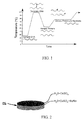
- FIG. 1 in an example of a thermal cycling process, high temperature thermal cycling is used to physically separate two stands of a double helix DNA. This process is commonly referred to as denaturing, wherein the linked strands of the DNA are separated into two single strands. Temperatures maintained during denaturing are typically in the range of 94° to 96° C. The two separated strands from the denatured DNA are used as templates to logarithmically replicate identical copies of the targeted segment of DNA.
- primers Upon reducing the temperature to approximately 52° C., synthetically designed primers bind to, or “anneal” to the template DNA strands such that they flank both sides of a target segment of denatured strands of DNA. DNA Polymerase and other cofactors then cause the primer to extend fully along the denatured strands of DNA and thus, a new double stranded piece of DNA is generated, wherein a lower controlled temperature in the range of 70° to 80° C. is maintained.
- the thermal cycling discussed above during denaturing and DNA replication is typically controlled in a laboratory machine.
- the machine includes electrical heating and cooling elements configured in electrical communication with thermal sensors in a closed loop control scheme. These machines are relatively large, immobile and expensive.
- a portable, disposable, low-powered thermal cycling in-vitro diagnostic apparatus is provided in accordance with one aspect of the invention.
- the apparatus is economical and it provides a quick, reliable and economical method for performing a thermally activated in-vitro diagnostic test on a selected specimen, such as DNA, for example.
- the apparatus automatically provides a predetermined thermal cycle over a predetermined time to allow a desired analysis of the specimen contained within the apparatus to be performed without need of human intervention.
- the apparatus produces exothermic and endothermic thermal energy, in a balanced and controlled environment via a chemical reaction between reactants contained within the apparatus.
- the reactants are provided and automatically combined in a predetermined manner to provide the desired thermal cycle needed to analyze the particular specimen. Accordingly, the apparatus in accordance with one aspect of the invention is wholly self-contained, and thus, is fully functional to perform the desired analysis without need of external apparatus.
- the apparatus can be configured for operable attachment to an external source of power.
- the external source of power can be provided as a hand held device that is configured for attachment to the in-vitro diagnostic apparatus.
- the separate source of power can be re-used, while the apparatus remains disposable.
- the external energy source can be configured to produce the desired energy profile within the apparatus.
- a simple circuit may provide for intermittent, or cycling of the energy source, resulting in a thermal cycling profile in the reaction chamber of the apparatus.
- a portable, disposable in-vitro diagnostic apparatus in accordance with another aspect of the invention, includes a body configured to be hand held.
- the body has a reaction medium supply chamber configured in selective fluid communication with a reaction chamber via a fluid conveying channel.
- the reaction chamber is located beneath a sample reaction chamber.
- the reaction medium supply chamber contains a reaction fluid therein and the reaction chamber contains a thermal reaction medium therein.
- the reaction fluid is selectively reactive with the thermal reaction medium to produce one of an endothermic or exothermic reaction beneath the sample reaction chamber.
- a conductive barrier separates the sample reaction chamber from the reaction chamber.
- the portable, disposable in-vitro diagnostic apparatus includes an overflow chamber downstream from the reaction chamber.
- a rupturable membrane selectively closes off the fluid conveying channel from the reaction medium supply chamber.
- a self-actuatable valve is disposed between the fluid conveying channel and the reaction chamber.
- the self-actuatable valve is movable between a closed position to close off the fluid conveying channel from the reaction chamber and an open position to allow fluid to flow from the fluid conveying channel into the reaction chamber.
- a method of conducting an in-vitro diagnostic test includes providing a body configured to be hand held having a reaction medium supply chamber with a reaction fluid contained therein in selective fluid communication with a thermal reaction medium contained in a reaction chamber via a fluid conveying channel wherein the reaction chamber is beneath a sample reaction chamber; disposing a sample in the sample reaction chamber; and dispensing a reaction fluid from the reaction medium supply chamber into the reaction chamber and producing one of an endothermic or exothermic reaction within the reaction chamber beneath the sample reaction chamber.
- the method further includes depressing a bulb and causing the reaction fluid to rupture a membrane and flow into the reaction chamber.
- the method further includes causing a self-actuable valve to move between open and closed positions to respectively allow and prevent the flow of the reaction fluid into the reaction chamber in response to the endothermic or exothermic reaction.
- the method further includes causing the self-actuable valve to move between the open and closed positions by buffering a portion of the thermal reaction medium.
- the method further includes reacting water with CuSO4 to produce an exothermic reaction.
- the method further includes reacting oxygen with iron to produce an exothermic reaction.
- the method further includes reacting citric acid with sodium bicarbonate to produce an endothermic reaction.
- FIG. 1 illustrates an example of a typical thermal cycle profile used in a denaturing and replication process of DNA
- FIG. 2 illustrates a perspective view of an exothermic or endothermic reaction member constructed in accordance with one aspect of the invention
- FIG. 3A illustrates a partial cross-sectional view of an exothermic or endothermic reaction member constructed in accordance with another aspect of the invention
- FIGS. 3B-3C illustrate cross-sectional views of an exothermic or endothermic reaction members constructed in accordance with further aspects of the invention
- FIGS. 4A-4B illustrate respective cross-sectional plan and perspective views of a deactivated disposable in-vitro diagnostic apparatus constructed in accordance with one aspect of the invention utilizing an exothermic or endothermic reaction member of FIG. 2 ;
- FIG. 5A illustrates the apparatus of FIGS. 4A-4B in an activated state
- FIG. 5B is a view similar to FIG. 5A illustrating a disposable in-vitro diagnostic apparatus constructed in accordance with another aspect of the invention utilizing exothermic or endothermic reaction members of at least one of FIGS. 3A-3C ;
- FIG. 6 is a perspective view of thermal transfer mechanism constructed in accordance with another aspect of the invention in combination with an exothermic or endothermic reaction member;
- FIGS. 7A-7C illustrate various states of a thermal control mechanism constructed in accordance with another aspect of the invention for regulating the thermal energy in an apparatus constructed in accordance with another aspect of the invention
- FIG. 8A illustrates a portion of a disposable in-vitro diagnostic apparatus constructed in accordance with the invention incorporating the thermal control mechanism of FIGS. 7A-7C with the thermal control mechanism shown in a maximum thermal energy conveying conduction state corresponding to FIG. 7B ;
- FIG. 8B shows the apparatus of FIG. 8A with the thermal control mechanism shown in a minimum thermal energy conveying convection state corresponding to FIG. 7C ;
- FIGS. 9A-9C illustrate a valve for regulating the flow of a reactant in a disposable in-vitro diagnostic apparatus constructed in accordance with another aspect of the invention
- FIGS. 10A-10B illustrate a disposable in-vitro diagnostic apparatus incorporating the valve of FIGS. 9A-9B with the valve being shown in respective open and closed states;
- FIG. 11A illustrates a perspective view of a fluid activation system of a disposable in-vitro diagnostic apparatus constructed in accordance with another aspect of the invention
- FIG. 11B is a cross-sectional plan view of the apparatus of claim 11 A;
- FIG. 12A illustrates an exploded perspective view of a disposable in-vitro diagnostic apparatus constructed in accordance with yet another aspect of the invention
- FIG. 12B illustrates the apparatus of FIG. 12A in combination with an external energy supply device
- FIG. 13A is a schematic of energy supply device for use on a disposable in-vitro diagnostic apparatus constructed in accordance with another aspect of the invention.
- FIG. 13B is exploded perspective view of a disposable in-vitro diagnostic apparatus constructed in accordance with yet another aspect of the invention including the energy supply device of FIG. 13A .
- disposable in-vitro diagnostic apparatus constructed in accordance with various presently preferred embodiments of the invention are illustrated, by way of example and without limitation.
- the apparatus 10 provide a quick, reliable and economical method for performing a thermally activated in-vitro diagnostic test on a selected specimen.
- the apparatus 10 is both economical in manufacture and in use, is readily portable, such that it is sized to be hand held for single use, whereupon the apparatus 10 is disposable after use, particularly given the low cost associated with its manufacture.
- the apparatus 10 can be provided as an all inclusive device, including an integral exothermic reaction heat producing or endothermic heat reducing and regulating mechanism, or it can be configured for operable electrical connection to a separate energy source to power a thermal reaction within the apparatus ( FIGS. 12A-12B ). If configured for operable attachment to a separate energy source, the energy source and/or the apparatus 10 can be configured to regulate the thermodynamics within the apparatus 10 , as discussed further below.
- the heat production via the exothermic chemical reaction or heat reduction via the endothermic reaction may be achieved by combining two or more elements or chemical substances, known as reactants, provided and contained entirely and integrally within the apparatus 10 .
- the combination of the reactants produces a product and a release of energy or a reduction of energy from the surrounding environment.
- the change in enthalpy, (thermodynamic potential) for an exothermic reaction is less than zero ( ⁇ 0), and thus, a larger value of energy released in the reaction is subtracted from a smaller value of energy used to initiate the reaction, the opposite being true for an endothermic reaction.
- exothermic reactants may be provided individually as, or as a combination of, solids, liquids and gasses. Some examples include:
- the endothermic reactants may be provided individually as, or as a combination of, solids, liquids and gasses. Some examples include:
- heat or cooling can be generated remotely from the sample being heated or cooled.
- Remote transport of thermal energy is provided by conduction through a material of high thermal conductivity, expressed in units of power per distance multiplied by temperature; W/m ⁇ K or W/m ° C., Btu/(hr ° F. ft 2 /ft).
- Remote heat transfer provides distribution of the thermal energy throughout the disposable device to locations desired, and also provides a source of varying temperature gradient to one or more points.
- the apparatus 10 can include a thermal cycling mechanism 12 to regulate and vary the heat or subtraction of energy transferred to or from to the sample.
- the thermal cycling mechanism 12 can be configured via a multi-layered composite, producing a thermal cycle based on the rate of reaction, quantity of reactants present and desired thermal cycling frequency.
- the thermal regulating mechanism 12 can include a valve member 13 , such as a bimetallic member, located between the thermal source and the sample being heated or cooled.
- the bimetallic member 13 is designed to move between an actuated and non-actuated position at predetermined temperatures, thus, providing an automated temperature regulation and a thermal cycling profile. This function can be applied to the above described remote thermal transport element ( FIG. 6 ) and to an electrical thermal energy control by acting as an electric switch ( FIGS. 12 and 13 ).
- thermal cycling within the apparatus 10 can be provided via a bimetallic, thermally actuated valve 14 , which, at a predetermined temperature, changes from concave ( FIG. 9A ) to convex ( FIG. 9B ) with respect to a valve port 16 .
- the valve 14 moves to a closed convex configuration ( FIG. 9B ), thus closing off flow of the reactant through the valve port 16 , and upon cooling the valve 14 moves to an open concave configuration ( FIGS. 9A and 9C ), thus restoring the flow of the reactant through the valve port 16 .
- the mechanical threshold of actuation results in a “snapping action” upon the valve member 13 “crossing over center”.
- heat may be generated by placement of an electrical heating element 18 proximal to the sample being heated.
- the heating element 18 may be actuated by an energy source 20 , such as a DC battery, by way of example, located integrally within the disposable apparatus 10 ( FIG. 13A-13B ), or from a separate energy source 20 external to the apparatus 10 , such as a DC battery, by way of example, which is configured to interface electrically with the disposable device ( FIGS. 12A-12B ).
- An electrical switch can be provided by a manual switch or by a low-level resistive or capacitance switch via contact with the sample fluid and coupled with a transistor on the apparatus 10 .
- a temperature reactive bimetallic switch may be employed, proximal to the fluid sample, such as discussed with regard to FIGS. 7A-7C , to regulate the temperature, or to produce a thermal cycling profile.
- the fluid reactant channeled to promote the thermal reaction may be introduced to the reaction chamber by a wick member 22 , and/or a controlled capillary channel.
- This mechanism and method of channeling the reactant can be configured to regulate the rate of fluid transfer as desired, thereby allowing the heat or cooling generated to be controlled, as desired.
- One or more fluid blisters 24 containing the fluid reactant F, or other sources of reactant, are provided to initiate the thermal reaction cycle.
- fluid reactants having different reactivity can be provided via the different sources of reactant, which provide a mechanism and method for varying thermal profiles. The sequential introduction of the fluid reactants at prescribed time intervals further facilitate regulating the thermal profile and timing thereof.
- an exothermic multi-layered composite medium shown as a disk stack 26 of alternating exothermic values, is illustrated in accordance with one aspect of the invention.
- the quantitative level of exothermic energy produced alternates in accordance to the desired thermal output level, thus, achieving the desired thermal cycle.
- the outer peripheral sides of the stack 26 can be shielded from the chemical reactant, such as by an inert coating, not subject to dissolution upon exposure to the reactive fluid.
- the exothermal reactant chemical discussed above, CuSO4 is provided as an example, and thus, it should be recognized that additional endothermic and exothermic reactive solids could be used.
- an exothermal or endothermal composite medium shown as a bead or sphere 28
- a bead or sphere 28 is illustrated in accordance with another aspect of the invention, which is a derivation of the exothermic composite disk stack 26 , with the primary difference of surface area and the number of individual points of reaction.
- a plurality of the composite spheres 28 provides an increased outer reactive surface area, and thus, provides a more intense reaction.
- the plurality of reactive spheres 28 can be provided in a predetermined configuration and quantity to produce the desired thermal cycling effect.
- exothermal or endothermal composite beads or spheres 30 are illustrated in accordance with another aspect of the invention.
- the exothermal or endothermal spheres 30 are similar to the previously discussed composite beads or spheres 28 of FIG. 3A , however, they are buffered with a coating 32 .
- the buffered coating 32 provides a timed-release of the active agent 34 in the exothermic reaction.
- Reactive spheres 30 having differing buffers 32 and thicknesses of buffer 32 result in a staged thermal cycle, as desired.
- a further difference with the buffered exothermal or endothermal composite spheres 30 over the spheres 28 of FIG. 3A is that the buffered spheres 30 of FIGS. 3B-3C each consist of only one reactive element 34 internal to the buffered coating 32 .
- an apparatus 10 constructed in accordance with one aspect of the invention, includes a unitized housing or body 11 sized to be hand held, and thus, the body 11 is readily carried in a palm of a hand.
- the body 11 can be constructed of any suitable materials, preferably relatively inexpensive moldable polymeric materials.
- the body 11 carries and provides the components of the apparatus 10 as a unitized, portable and disposable assembly.
- the body 11 carries an exothermal or endothermal composite series of plates or disks 26 , also referred to as a “reaction” stack, such as discussed and shown in FIG. 2 , residing under a sample reaction chamber 36 .
- the chamber 36 is separated from the thermal reaction stack 26 by a thermally conductive barrier 38 , thus isolating the byproducts of the thermal reaction from the sample 40 being heated or cooled.
- a self-contained reactive fluid F is encapsulated and contained in a flexible and sealed elastic bulb or blister, also referred to as a reaction fluid supply chamber 24 , shown as a “blister pack”, that is in selective fluid communication with the thermal reaction medium or stack 26 contained in a reaction chamber 50 via a fluid conveying channel 42 , and to a distal (downstream of the sample 40 ) waste/overflow chamber 44 , which is vented to atmosphere or another chamber.
- the sample chamber 36 may be covered and seal off by an optically clear cover window 46 to permit visual or optical analysis of the reaction within the chamber 36 .
- the blister 24 containing the reactive fluid F is depressed via an externally applied force, such as by manually depressing the blister 24 with a thumb or finger, for example, thereby causing the reactive fluid to selectively rupture a membrane 48 closing off the channel 42 .
- the fluid passes through the channel 42 to the reaction chamber 50 containing the thermal reaction stack 26 .
- the stack 26 reacts with the reactive fluid F, thereby producing an endothermic or exothermic release of energy.
- the thermally conductive barrier 38 conducts or removes the thermal energy to or from the sample 40 being heated or cooled.
- FIG. 5 B is similar to FIG. 5A , however, it incorporates at least one or more types of the exothermal or endothermal reactive beads or spheres 28 , 30 discussed above and shown in FIGS. 3A-3C .
- the reaction is vented, thus balancing the pressures present within the disposable apparatus 10 .
- FIG. 6 depicts the use of a thermal conductor 54 to transfer the thermal energy to or from the point of an assay reaction. This allows remote generation of energy, thus, multiple sources of energy may be directed to a single point or location. The figure discussed above represent only a single location of energy.
- FIG. 7A depicts the thermally cycling mechanism in the form of a deformable bimetallic or shape memory alloy disk 12 .
- the objective of this component is to regulate the level of thermal energy extended to or from the assay chamber 36 .
- the thermal barriers 38 shown in FIGS. 4A-4B and 5 A- 5 B can be provided as such, such as via a bimetallic, shape memory alloy or other thermally deformable material, thus allowing for the thermal barrier 12 to automatically change its configuration at a prescribed temperature.
- the deformable thermal barrier 12 is in contact with the thermally conductive member 38 prior to the thermal reaction.
- the bias shape of FIG. 7B provides positive physical abutment of the thermal barrier 12 with the thermally conductive member 38 upon assembly of the thermal barrier 12 and prior to heating or cooling. It should be recognized that the thermal barrier 12 can be constructed having any desired shape.
- FIG. 7C depicts the thermally deformable, or shape memory alloy barrier 12 , deflected at a prescribed temperature, lifting off of the thermally conductive member 38 , thus limiting the conduction of energy from the thermal reaction chamber 50 via an insulation gap G.
- the natural resonate frequency governing the period between deflection and non-deflection is a function of design and temperature. This frequency results in the desired thermal cycling between the configurations shown in FIGS. 7B and 7C .
- FIG. 8A illustrates an apparatus 10 including the thermally deformable barrier 12 of FIGS. 7A-7C , in the un-actuated state. While, in its un-actuated state, thermal energy resulting from a combination of the fluid reactant F and the exothermal or endothermal composite medium is conducted through the thermally conductive barrier 38 and through the thermally deformable barrier 12 .
- FIG. 8B depicts the thermally deformable barrier 12 deflected (actuated) at a prescribed temperature to provide the gap G, thus limiting the conduction of energy from the thermal reaction chamber 50 to the sample chamber 36 .
- the thermally deformable barrier 12 looses physical conduct with the thermally conductive barrier 38 , thus eliminating conduction of heat or cooling from the reaction chamber 50 to the sample chamber 36 .
- the thermally deformed material 12 returns to its physically conductive position ( FIG. 8A ) upon cooling. The cooling process occurs due to the lack of physical contact with the heated or cooled conduction surface 38 .
- FIGS. 9A-9B depict the valve 14 comprised of a thermally deformable or shape memory alloy device 13 , capable of deflecting at a prescribed temperature, thus regulating the flow of reaction fluid F to the reaction chamber 50 .
- the valve 14 is shown in the open position, wherein the fluid F is able to flow to the reaction chamber 50 .
- a thermal conductor 54 as described and shown in FIG. 6 , may be adapted to this design to allow control of the valve 14 from a remote location. This valve 14 would also produce a thermal cycling, upon opening and closing, to regulate a thermal reaction.
- FIG. 9B depicts the valve 14 in the closed position, thereby preventing the flow of the fluid reactant F to the reaction chamber 50 .
- the thermal reaction “down-stream” of the valve 14 is impeded, thus reducing the thermal energy the valve 14 is exposed to, resulting in a reopening of the valve 14 .
- FIG. 9C depicts a thermally deformable shape memory valve 14 with electrical contacts 56 for electrical actuation.
- Nitinol a common shape memory alloy undergoes elastic deformation upon thermal or electrical exposure. The valve 14 deflects upon passing current through the valve 14 .
- FIG. 10A illustrates an apparatus 10 incorporating the valve 14 in FIGS. 9A-9C , and also the thermally deformable member 12 described in FIGS. 7A-8B .
- the valve 14 is shown in the open position, permitting flow of the liquid reaction agent F to the solid reactant.
- FIG. 10B depicts the integrated thermal valve 14 in the closed position, thus inhibiting the flow of the liquid reaction agent into fluid contact with the solid reactant 26 .
- FIG. 11A depicts a device for introducing the reaction fluid into the reaction chamber remotely via the wick member 22 .
- the wick 22 regulates the flow of the reaction fluid into the reaction chamber 50 , thus regulating the rate of the reaction.
- the wick 22 can be provided having any desired cross-sectional shape along its length, and further, can be formed from any desired wicking material, thereby allowing the flow rate of wicking of the reaction fluid to be precisely controlled.
- FIG. 11B is a cross-section of an apparatus 10 incorporating the remote fluid wicking device 22 of FIG. 11A .
- FIG. 12A depicts a disposable apparatus 10 constructed in accordance with another aspect of the invention including the embedded thermal element 18 and electrical contacts 58 for interface with the electrical energy source 20 .
- the thermal element 18 includes a resistive element 60 embedded in the reaction chamber 50 .
- the external energy source 20 provides the current to heat the resistive elements 60 .
- FIG. 12B shows the apparatus 10 in FIG. 12A interfacing with an external energy source 20 .
- the energy source 20 is capable of producing an energy profile, which in turn, produces the desired thermal profile.
- a simple circuit may provide for intermittent, or cycling of the energy source 20 , resulting in a thermal cycling profile in the reaction chamber 50 .
- FIG. 13A is a schematic of a “on-device”, battery powered heating element, with a simple transistor relay.
- the transistor receives its signal from a pair of contacts embedded in the reaction chamber 50 which are “connected” upon contact with the fluid sample being heated.
- the fluid sample provides and electrical path between the contacts, thus completing the circuit.
- the addition of a thermal switch would provide a thermal cycling profile.
- FIG. 13B depicts an embodiment of the schematic in FIG. 13A in a disposable apparatus 10 .
- the switching transistor provides the means to turn on and of the heating element, and when coupled with one of the thermally cycling devices describe prior, may also yield the thermal cycling profile.
Landscapes
- Chemical & Material Sciences (AREA)
- Health & Medical Sciences (AREA)
- Chemical Kinetics & Catalysis (AREA)
- Life Sciences & Earth Sciences (AREA)
- General Health & Medical Sciences (AREA)
- Organic Chemistry (AREA)
- Clinical Laboratory Science (AREA)
- Analytical Chemistry (AREA)
- Molecular Biology (AREA)
- Zoology (AREA)
- Biochemistry (AREA)
- Engineering & Computer Science (AREA)
- Proteomics, Peptides & Aminoacids (AREA)
- Wood Science & Technology (AREA)
- Hematology (AREA)
- Bioinformatics & Cheminformatics (AREA)
- Microbiology (AREA)
- Biotechnology (AREA)
- General Engineering & Computer Science (AREA)
- Biophysics (AREA)
- Genetics & Genomics (AREA)
- Physics & Mathematics (AREA)
- Immunology (AREA)
- Dispersion Chemistry (AREA)
- Apparatus Associated With Microorganisms And Enzymes (AREA)
Abstract
Description
CuSO4+5H2O→CuS4·5H2O+HEAT; or
4Fe+3O2→2Fe2O3+HEAT.
H3C6H5O7(aq)+3NaHCO3(s)→3CO2(g)+3H2O(l)+Na3C6H5O7(aq).
Claims (7)
Priority Applications (2)
| Application Number | Priority Date | Filing Date | Title |
|---|---|---|---|
| US13/855,331 US9279151B2 (en) | 2012-04-02 | 2013-04-02 | Disposable thermal in-vitro diagnostic apparatus and method of conducting an in-vitro diagnostic test |
| US15/044,852 US9561507B2 (en) | 2012-04-02 | 2016-02-16 | Disposable thermal in-vitro diagnostic apparatus |
Applications Claiming Priority (2)
| Application Number | Priority Date | Filing Date | Title |
|---|---|---|---|
| US201261619406P | 2012-04-02 | 2012-04-02 | |
| US13/855,331 US9279151B2 (en) | 2012-04-02 | 2013-04-02 | Disposable thermal in-vitro diagnostic apparatus and method of conducting an in-vitro diagnostic test |
Related Child Applications (1)
| Application Number | Title | Priority Date | Filing Date |
|---|---|---|---|
| US15/044,852 Division US9561507B2 (en) | 2012-04-02 | 2016-02-16 | Disposable thermal in-vitro diagnostic apparatus |
Publications (2)
| Publication Number | Publication Date |
|---|---|
| US20130288257A1 US20130288257A1 (en) | 2013-10-31 |
| US9279151B2 true US9279151B2 (en) | 2016-03-08 |
Family
ID=49477632
Family Applications (2)
| Application Number | Title | Priority Date | Filing Date |
|---|---|---|---|
| US13/855,331 Active 2033-07-08 US9279151B2 (en) | 2012-04-02 | 2013-04-02 | Disposable thermal in-vitro diagnostic apparatus and method of conducting an in-vitro diagnostic test |
| US15/044,852 Active US9561507B2 (en) | 2012-04-02 | 2016-02-16 | Disposable thermal in-vitro diagnostic apparatus |
Family Applications After (1)
| Application Number | Title | Priority Date | Filing Date |
|---|---|---|---|
| US15/044,852 Active US9561507B2 (en) | 2012-04-02 | 2016-02-16 | Disposable thermal in-vitro diagnostic apparatus |
Country Status (1)
| Country | Link |
|---|---|
| US (2) | US9279151B2 (en) |
Families Citing this family (5)
| Publication number | Priority date | Publication date | Assignee | Title |
|---|---|---|---|---|
| US10335786B2 (en) * | 2013-05-31 | 2019-07-02 | Pixcell Medical Technologies Ltd. | Cartridge for preparing a sample fluid containing cells for analysis |
| US9527077B2 (en) * | 2015-01-29 | 2016-12-27 | David W. Wright | Diagnostic cartridge, fluid storage and delivery apparatus therefor and methods of construction thereof |
| NZ735303A (en) | 2015-03-06 | 2023-06-30 | Microgem Int Plc | Method and device for preparing and extracting a biomolecule |
| US20220254528A1 (en) * | 2016-04-19 | 2022-08-11 | Matthew J. Memmott | Emergency Heat Removal in a Light Water Reactor Using a Passive Endothermic Reaction Cooling System (PERCS) |
| US20210170396A1 (en) * | 2018-01-16 | 2021-06-10 | Hewlett-Packard Development Company, L.P. | Fluid testing |
Citations (2)
| Publication number | Priority date | Publication date | Assignee | Title |
|---|---|---|---|---|
| US4753241A (en) * | 1984-06-01 | 1988-06-28 | Fastencold, Inc. | Method of forming and using a therapeutic device |
| US20050129582A1 (en) * | 2003-06-06 | 2005-06-16 | Micronics, Inc. | System and method for heating, cooling and heat cycling on microfluidic device |
-
2013
- 2013-04-02 US US13/855,331 patent/US9279151B2/en active Active
-
2016
- 2016-02-16 US US15/044,852 patent/US9561507B2/en active Active
Patent Citations (2)
| Publication number | Priority date | Publication date | Assignee | Title |
|---|---|---|---|---|
| US4753241A (en) * | 1984-06-01 | 1988-06-28 | Fastencold, Inc. | Method of forming and using a therapeutic device |
| US20050129582A1 (en) * | 2003-06-06 | 2005-06-16 | Micronics, Inc. | System and method for heating, cooling and heat cycling on microfluidic device |
Non-Patent Citations (2)
| Title |
|---|
| Ahn et al., Proceedings of the IEEE, vol. 92, No. 1, pp. 154-170, Jan. 2004. * |
| Emdtadmin., European medical Device technology, http://www.emdt.co.uk/article/microfluidics-platform-vitro-testing., pp. 1-2, Mar. 1, 2008. * |
Also Published As
| Publication number | Publication date |
|---|---|
| US9561507B2 (en) | 2017-02-07 |
| US20130288257A1 (en) | 2013-10-31 |
| US20160158760A1 (en) | 2016-06-09 |
Similar Documents
| Publication | Publication Date | Title |
|---|---|---|
| US9561507B2 (en) | Disposable thermal in-vitro diagnostic apparatus | |
| Zhang et al. | Point-of-care multiplexed assays of nucleic acids using microcapillary-based loop-mediated isothermal amplification | |
| US8722417B2 (en) | Thermoelectric sensor for analytes in a fluid and related method | |
| TWI271218B (en) | Microfluidic system for analyzing nucleic acids | |
| JPWO2004029241A1 (en) | Method for amplifying nucleic acid by electromagnetic induction heating, reaction vessel and reaction apparatus used therefor | |
| JP2013172724A (en) | Method and device for conducting biochemical or chemical reaction at multiple temperatures | |
| US20140287414A1 (en) | System and method for analyzing dna using application of mobile device | |
| CN107923927A (en) | The method of drop microfluidic device and sensing measurement result therein | |
| JP6576439B2 (en) | Flow assay having at least one valve for controlling flow rate with an electric drive and method thereof | |
| Prakash et al. | Droplet microfluidic chip based nucleic acid amplification and real-time detection of influenza viruses | |
| EP3380239B1 (en) | Systems and devices for microfluidic instrumentation | |
| Stetter et al. | Sensors: engineering structures and materials from micro to nano | |
| US20120091335A1 (en) | Surface sampling systems for collecting volatilized samples | |
| Mavraki et al. | A continuous flow μPCR device with integrated microheaters on a flexible polyimide substrate | |
| Dhatterwal et al. | Digital flow-based cyber-physical microfluidic biochips | |
| Futane et al. | Emerging Trends In Computational Biosensors: Challenges And Future Directions | |
| KR101577524B1 (en) | Ion selective micropore device and fabrication method thereof | |
| Lee et al. | Thermal feedback system from robot hand for telepresence | |
| Sridharamurthy et al. | A microfluidic device to acquire gaseous samples via surface tension held gas-liquid interface | |
| KR20140028431A (en) | Pcr chip for detecting electrochemcial signal comprising heating block of repetitively disposed heater unit, real-time pcr device comprising the same, and real-time pcr using the same | |
| Khaji et al. | Integrated cooling system for microfluidic PDMS devices used in biological microscopy studies | |
| TW201215451A (en) | Liquid droplet device capable of being heated | |
| Park et al. | A simple on-chip self-diagnosis/self-calibration method of oxygen microsensor using electrochemically generated bubbles | |
| Warden et al. | Portable Infrared Isothermal PCR Platform for Multiple Sexually Transmitted Diseases Strand Detection | |
| KR20140013462A (en) | Real-time pcr device for detecting electrochemcial signal comprising heating block of repetitively disposed heater unit, and real-time pcr using the same |
Legal Events
| Date | Code | Title | Description |
|---|---|---|---|
| STCF | Information on status: patent grant |
Free format text: PATENTED CASE |
|
| MAFP | Maintenance fee payment |
Free format text: PAYMENT OF MAINTENANCE FEE, 4TH YR, SMALL ENTITY (ORIGINAL EVENT CODE: M2551); ENTITY STATUS OF PATENT OWNER: SMALL ENTITY Year of fee payment: 4 |
|
| AS | Assignment |
Owner name: WI, INC., COLORADO Free format text: ASSIGNMENT OF ASSIGNORS INTEREST;ASSIGNOR:WRIGHT, DAVID W.;REEL/FRAME:056735/0272 Effective date: 20210629 |
|
| AS | Assignment |
Owner name: CREGANNA UNLIMITED COMPANY, IRELAND Free format text: ASSIGNMENT OF ASSIGNORS INTEREST;ASSIGNOR:WI INC.;REEL/FRAME:058700/0111 Effective date: 20211126 |
|
| MAFP | Maintenance fee payment |
Free format text: PAYMENT OF MAINTENANCE FEE, 8TH YR, SMALL ENTITY (ORIGINAL EVENT CODE: M2552); ENTITY STATUS OF PATENT OWNER: SMALL ENTITY Year of fee payment: 8 |
|
| FEPP | Fee payment procedure |
Free format text: ENTITY STATUS SET TO UNDISCOUNTED (ORIGINAL EVENT CODE: BIG.); ENTITY STATUS OF PATENT OWNER: LARGE ENTITY |
|
| MAFP | Maintenance fee payment |
Free format text: PAYMENT OF MAINTENANCE FEE UNDER 1.28(C) (ORIGINAL EVENT CODE: M1559); ENTITY STATUS OF PATENT OWNER: LARGE ENTITY |