US9276507B2 - Rotary drive system, method for controlling an inverter and associated computer program - Google Patents
Rotary drive system, method for controlling an inverter and associated computer program Download PDFInfo
- Publication number
- US9276507B2 US9276507B2 US14/247,587 US201414247587A US9276507B2 US 9276507 B2 US9276507 B2 US 9276507B2 US 201414247587 A US201414247587 A US 201414247587A US 9276507 B2 US9276507 B2 US 9276507B2
- Authority
- US
- United States
- Prior art keywords
- formula
- point
- zone
- homopolar
- drive system
- Prior art date
- Legal status (The legal status is an assumption and is not a legal conclusion. Google has not performed a legal analysis and makes no representation as to the accuracy of the status listed.)
- Active, expires
Links
Images
Classifications
-
- H—ELECTRICITY
- H02—GENERATION; CONVERSION OR DISTRIBUTION OF ELECTRIC POWER
- H02P—CONTROL OR REGULATION OF ELECTRIC MOTORS, ELECTRIC GENERATORS OR DYNAMO-ELECTRIC CONVERTERS; CONTROLLING TRANSFORMERS, REACTORS OR CHOKE COILS
- H02P25/00—Arrangements or methods for the control of AC motors characterised by the kind of AC motor or by structural details
- H02P25/02—Arrangements or methods for the control of AC motors characterised by the kind of AC motor or by structural details characterised by the kind of motor
- H02P25/022—Synchronous motors
- H02P25/03—Synchronous motors with brushless excitation
-
- H02P6/002—
-
- H—ELECTRICITY
- H02—GENERATION; CONVERSION OR DISTRIBUTION OF ELECTRIC POWER
- H02M—APPARATUS FOR CONVERSION BETWEEN AC AND AC, BETWEEN AC AND DC, OR BETWEEN DC AND DC, AND FOR USE WITH MAINS OR SIMILAR POWER SUPPLY SYSTEMS; CONVERSION OF DC OR AC INPUT POWER INTO SURGE OUTPUT POWER; CONTROL OR REGULATION THEREOF
- H02M7/00—Conversion of AC power input into DC power output; Conversion of DC power input into AC power output
- H02M7/42—Conversion of DC power input into AC power output without possibility of reversal
- H02M7/44—Conversion of DC power input into AC power output without possibility of reversal by static converters
- H02M7/48—Conversion of DC power input into AC power output without possibility of reversal by static converters using discharge tubes with control electrode or semiconductor devices with control electrode
- H02M7/53—Conversion of DC power input into AC power output without possibility of reversal by static converters using discharge tubes with control electrode or semiconductor devices with control electrode using devices of a triode or transistor type requiring continuous application of a control signal
- H02M7/537—Conversion of DC power input into AC power output without possibility of reversal by static converters using discharge tubes with control electrode or semiconductor devices with control electrode using devices of a triode or transistor type requiring continuous application of a control signal using semiconductor devices only, e.g. single switched pulse inverters
- H02M7/5387—Conversion of DC power input into AC power output without possibility of reversal by static converters using discharge tubes with control electrode or semiconductor devices with control electrode using devices of a triode or transistor type requiring continuous application of a control signal using semiconductor devices only, e.g. single switched pulse inverters in a bridge configuration
- H02M7/53871—Conversion of DC power input into AC power output without possibility of reversal by static converters using discharge tubes with control electrode or semiconductor devices with control electrode using devices of a triode or transistor type requiring continuous application of a control signal using semiconductor devices only, e.g. single switched pulse inverters in a bridge configuration with automatic control of output voltage or current
- H02M7/53875—Conversion of DC power input into AC power output without possibility of reversal by static converters using discharge tubes with control electrode or semiconductor devices with control electrode using devices of a triode or transistor type requiring continuous application of a control signal using semiconductor devices only, e.g. single switched pulse inverters in a bridge configuration with automatic control of output voltage or current with analogue control of three-phase output
-
- H—ELECTRICITY
- H02—GENERATION; CONVERSION OR DISTRIBUTION OF ELECTRIC POWER
- H02P—CONTROL OR REGULATION OF ELECTRIC MOTORS, ELECTRIC GENERATORS OR DYNAMO-ELECTRIC CONVERTERS; CONTROLLING TRANSFORMERS, REACTORS OR CHOKE COILS
- H02P21/00—Arrangements or methods for the control of electric machines by vector control, e.g. by control of field orientation
- H02P21/0003—Control strategies in general, e.g. linear type, e.g. P, PI, PID, using robust control
- H02P21/0021—Control strategies in general, e.g. linear type, e.g. P, PI, PID, using robust control using different modes of control depending on a parameter, e.g. the speed
Definitions
- the present invention relates to a rotary drive system, a method for controlling an inverter and an associated computer program.
- control device In some drive systems, the control device is intended to control the inverter so as to obtain a zero homopolar current in the electric motor, so as to meet some objectives, whereas in other drive systems, the control device is intended to control the inverter so as to obtain a non-zero homopolar current in the electric motor, so as to meet other objectives.
- control device comprises:
- the means for selecting a formula are intended to make the selection based on at least one parameter relating to the rotary drive system.
- the parameter(s) relating to the rotary drive system include an operating characteristic of the electric motor, for example the rotational speed thereof.
- the means for selecting a formula comprise:
- the means for selecting a formula comprise at least one definition of a zone associated with a formula for calculating a homopolar current set-point.
- the means for selecting a formula comprise at least one definition of a zone associated with a formula for calculating a homopolar voltage set-point.
- the means for selecting a formula comprise at least one definition of a zone associated with a formula for calculating a set-point in the form of a homopolar harmonic, for example in the form of the first homopolar harmonic.
- the means for selecting a formula comprise at least one definition of a zone associated with a formula for supplying a zero set-point.
- the invention also relates to a method for controlling an inverter for connecting, to a direct voltage source, each phase of an electric motor having an axis of rotation, and comprising independent phases having directions about the axis of rotation, the method comprising:
- the invention also relates to a computer program comprising instructions which, when run on a computer, cause the computer to perform the steps of a method according to the invention.
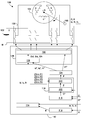
- FIG. 1 is a diagram of a rotary drive system according to the invention
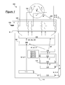
- FIG. 2 is a diagram illustrating a plurality of operating zones
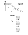
- FIG. 3 is a block diagram of a method for controlling an inverter of the system in FIG. 1 .
- the rotary drive system 100 firstly comprises a direct voltage source 102 for supplying a direct voltage V in relation to a reference electric potential M (ground).
- the rotary drive system 100 further comprises an electric motor 104 .
- the electric motor 104 comprise a stator (not shown) and a rotor (not shown) for rotating in relation to the stator about an axis of rotation A, at a speed ⁇ and supplying a torque, referred to as an electromagnetic torque C.
- the electric motor 104 further comprises three phases a, b, c having directions evenly distributed about the axis of rotation A, and p poles.
- Each phase a, b, c has two terminals, and the phases a, b, c are independent, i.e. they are not connected by one of the terminals thereof to a common point, commonly referred to as “neutral”.
- the phases a, b, c are intended to be respectively traversed by phase currents ia, ib, is and to have phase voltages va, vb, vc between the terminals thereof.
- the rotary drive system 100 further comprises an inverter 106 for connecting each phase a, b, c of the electric motor 104 to the direct voltage source 102 .
- the inverter 106 comprises six arms, each associated with a respective terminal of the phases a, b, c. Each arm is intended to connect the associated terminal thereof with the voltage V or the ground M. Each arm thus comprises two switches controlled in series, connected at the centre thereof to the associated terminal.
- the inverter 106 is thus intended to apply to each phase a, b, c: the voltage +V, the reverse thereof ⁇ V, or zero voltage when the two terminals of the phase in question are both connected to the same point (V or M).
- the rotary drive system 100 further comprises a sensor 108 for measuring the rotation speed ⁇ of the rotor in relation to the stator, the phase currents ia, ib, ic and the angle, annotated ⁇ , between the rotor and the stator.
- the rotary drive system 100 further comprises a control device 110 for controlling the inverter 106 , the control device 110 being intended to supply a command to the inverter 106 for controlling the inverter 106 according to the speed ⁇ , the phase currents ia, ib, ic, the angle ⁇ and a rotational speed set-point ⁇ * of the rotor in relation to the stator.
- the speed set-point ⁇ * is for example received from a speed regulator when the system 100 is implemented in a motor vehicle.
- the command of the inverter 106 generally consists of very high-frequency switch opening/closing commands.
- the control device 110 is for example embodied in the form of a computer. In this case, the means of the control device 110 detailed hereinafter are for example embodied in the form of computer programs recorded on a computer medium and run by the computer, and/or in the form of dedicated electronic circuits of the computer.
- the control device 110 firstly comprises means 112 for determining a useful angle ⁇ ′ based on the mechanical angle ⁇ .
- the useful angle ⁇ ′ is for example equal to this mechanical angle ⁇ , or equal to the electrical angle equal to this mechanical angle ⁇ multiplied by the number of pairs of poles p of the electric motor 104 .
- the control device 110 further comprises means 114 for applying Park's transformation (also referred to as dq0 transformation) to the phase current ia, ib, ic for determining the direct current id, the quadrature current iq and the homopolar current ih.
- Park's transformation also referred to as dq0 transformation
- the currents id, iq and ih are given according to the formula:
- each phase current ia, ib is comprises one component from the direct current id and quadrature current iq, and one component from the homopolar current ih.
- the control device 110 further comprises means 116 for determining an electromagnetic torque set-point C* of the electric motor 104 based on the speed ⁇ and the speed set-point ⁇ *.
- the control device 110 further comprises means 118 for selecting a formula, said means 118 being intended to select a formula F from different predefined formulas, for example saved in a memory.
- the predefined formulas are four in number in the example described and annotated F 1 , F 2 , F 3 , F 4 .
- Each predefined formula F 1 , F 2 , F 3 , F 4 is intended to calculate either a homopolar voltage set-point, or a homopolar current set-point.
- each formula defines the homopolar electrical quantity to be controlled: either the homopolar current ih, or the homopolar voltage vh.
- at least one formula is intended to calculate a homopolar current set-point, and at least one other formula is intended to calculate a homopolar voltage set-point.
- the formulas F 1 , F 2 are intended to calculate a homopolar current set-point, whereas the formulas F 3 , F 4 are intended to calculate a homopolar voltage set-point.
- the formulas F 1 , F 2 , F 3 , F 4 will be described in more detail hereinafter.
- the selection is made based on at least one parameter relating to the rotary drive system 100 . More specifically, in the example described, two parameters relating to the electric motor 104 are used: the speed ⁇ and the torque set-point C*.
- the speed ⁇ is an operating characteristic of the electric motor 104
- the torque set-point C* is a control characteristic of the electric motor 104 .
- the means 118 for selecting a formula comprise definitions of zones of the space defined by the parameters relating to the drive system 100 . These definitions are for example saved in a memory. In the example described wherein two parameters relating to the electric motor 104 are used, this space is two-dimensional, i.e. plane. In the example described, four zones Z 1 , Z 2 , Z 3 , Z 4 are defined and each zone Z 1 , Z 2 , Z 3 , Z 4 is respectively associated with one of the formulas F 1 , F 2 , F 3 , F 4 . Furthermore, in the example described, each zone Z 1 , Z 2 , Z 3 , Z 4 is associated with a formula for calculating the direct current set-point id* and with a formula for calculating the quadrature current set-point iq*.
- the means 118 for selecting a formula firstly comprise means 120 for determining a zone, said means 120 being intended to determine, from the predefined zones, the zone Z corresponding to the parameters relating to the electric motor 104 , i.e. in the example described, corresponding to the speed ⁇ and to the torque set-point C*.
- the means 118 for selecting a formula further comprise means 122 for retrieving the formula F associated with the zone Z determined by the means 120 for determining the zone, and retrieving the formulas for calculating the direct and quadrature current set-point.
- the control device 110 further comprises means 124 for determining a set-point, said means 124 being intended to determine a direct current set-point id*, a quadrature current set-point iq* and either a homopolar current set-point ih, or a homopolar voltage set-point vh, by applying the formulas selected and particularly the formula F selected for the homopolar quantity.
- the control device 110 further comprises means 126 for determining a command, said means 126 being intended to determine the command of the inverter 106 based on the set-points determined, and in particular the homopolar current set-point, or the homopolar voltage set-point, according to the circumstances.
- the means 126 for determining a command comprises means 128 for determining deviations, said means 128 being intended to determine direct current deviations ⁇ id, a quadrature current deviation ⁇ iq and, when the homopolar electrical quantity to be controlled is the homopolar current ih, a homopolar current deviation ⁇ ih. These deviations are determined based on the comparison, respectively, of the direct current id with the direct current set-point id*, of the quadrature current iq with the quadrature current set-point iq*, and of the homopolar current ih with the homopolar current set-point ih*.
- the means 126 for determining a command further comprise means 130 for calculating a command, said means 130 being intended to calculate the command of the inverter 106 based on the deviations ⁇ id, ⁇ iq and ⁇ ih when the homopolar electrical quantity to be controlled is the homopolar current set-point ih, or based on the previous deviations ⁇ id, ⁇ iq and the homopolar voltage set-point vh* when the homopolar electrical quantity to be controlled is the homopolar voltage vh.
- zones Z 1 , Z 2 , Z 3 , Z 4 are defined in the plane of the parameters relating to the electric motor 104 , i.e. in the plane C* ⁇ .
- the zone Z 1 corresponds to a torque set-point C* less than a threshold C 1 and to a speed ⁇ less than a threshold ⁇ 1 .
- the speed threshold ⁇ 1 preferably corresponds to phase voltages va, vb, vc all equal to voltage V of the direct voltage source 102 .
- the zone Z 2 corresponds to a torque set-point C* between the threshold C 1 and a threshold C 2 , and to a speed ⁇ less than the threshold ⁇ 1 .
- the homopolar current set-point ih* is in the form of a third harmonic, i.e. a frequency wave three times higher than the fundamental frequency of the phase currents, this fundamental frequency having a frequency equal to the rotational speed ⁇ multiplied by the number of pairs of poles p of the electric motor 104 .
- the coefficient k 2 and the phase shift ⁇ 2 are chosen so as to reduce the peak value of the phase currents ia, ib, ic. In theory, the optimal case is obtained when the phase shift ⁇ 2 is zero.
- each phase current ia, ib, ic is limited by a current limit imax corresponding to the structure of the inverter 106 .
- the fundamental component, annotated H 1 is thus also limited by this limit imax.
- each phase current ia, ib, ic supplied by the inverter 106 comprises a fundamental component H 1 and a homopolar component H 3 .
- the direct and quadrature current set-points id*, iq* give rise to the presence of a fundamental component H 1 greater than imax, whereas the set-point of the homopolar component H 3 is chosen to reduce the peak value of the current, such that the sum of the fundamental component H 1 and the homopolar component H 3 remains below the current limit imax.
- the following formulas sum up the above: H 1+ H 3 ⁇ i max Max( H 1)> i max
- the electric motor 104 responding to the fundamental current component H 1 received (and very slightly to the homopolar component H 3 ), can attain greater torques in the zone Z 2 than in the zone Z 1 since the fundamental component is higher, at the expense of losses arising from the presence of the homopolar component H 3 .
- the zone Z 3 corresponds to a speed ⁇ between the threshold ⁇ 1 and a threshold ⁇ 2 , and to a torque set-point C* less than a threshold C 3 which decreases when the speed ⁇ increases, from the threshold C 1 when the speed ⁇ is equal to the threshold ⁇ 1 up to a zero threshold when the speed ⁇ is equal to the threshold ⁇ 2 .
- the homopolar voltage set-point vh* is in the form of a third harmonic, i.e. a frequency wave three times higher than the fundamental frequency of the phase currents, this fundamental frequency having a frequency equal to the rotational speed ⁇ multiplied by the number of pairs of poles p of the electric motor 104 .
- each phase voltage va, vb, vc is limited by the voltage V of the direct voltage source 102 .
- the fundamental component, annotated H 1 is thus also limited by this voltage V.
- each phase voltage va, vb, vc supplied by the inverter 106 comprises a fundamental component H 1 and a homopolar component H 3 .
- the direct and quadrature current set-points id*, iq* give rise to the presence of a fundamental component H 1 greater than V, whereas the set-point of the homopolar component H 3 is chosen to reduce the peak value of the voltage, such that the sum of the fundamental component H 1 and the homopolar component H 3 remains below the voltage limit V.
- the following formulas sum up the above: H 1+ H 3 ⁇ V Max( H 1)> V
- the electric motor 104 responding to the fundamental voltage component H 1 received (and very slightly to the homopolar component H 3 ), can attain greater speeds in the zone Z 3 than in the zone Z 1 since the fundamental component is higher, at the expense of losses arising from the presence of the homopolar component H 3 .
- the zone Z 4 corresponds to a speed ⁇ between the threshold ⁇ 1 and a threshold ⁇ 3 , and a torque set-point C* between the zone 3 and a threshold C 4 which decreases when the speed ⁇ increases, from the threshold C 2 when the speed ⁇ is equal to the threshold ⁇ 1 up to a zero threshold when the speed ⁇ is equal to the threshold ⁇ 3 .
- each phase voltage va, vb, vc supplied by the inverter 106 comprises a fundamental component H 1 and a homopolar component H 3 .
- each phase current ia, ib, is supplied by the inverter 106 comprises a fundamental component H′ 1 and a homopolar component H′ 3 .
- the direct and quadrature current set-points id*, iq* give rise to the presence of a fundamental component H 1 greater than V, and, at the same time, the presence of a fundamental component H′ 1 greater than imax.
- the set-point of the homopolar component H 3 is chosen, on the one hand, so as to reduce the peak value of the voltage, such that the sum of the fundamental component H 1 and the homopolar component H 3 remains below the voltage limit V, and, on the other hand, so as to induce a homopolar component H′ 3 decreasing the peak current value such that the sum of the fundamental component H′ 1 and the homopolar component H′ 3 remains below the current limit imax.
- the following formulas sum up the above: H 1+ H 3 ⁇ V H′ 1+ H′ 3 ⁇ i max Max( H 1)> V Max( H′ 1)> i max
- the electric motor 104 responding to the fundamental components H 1 , H′ 1 received (and very slightly to the homopolar components H 3 , H′ 3 ), can attain greater speeds and torques in the zone Z 4 than in the zone Z 3 since the fundamental components H 1 , H′ 1 are higher therein, at the expense of losses arising from the presence of the homopolar components H 3 , H′ 3 .
- the sensor 108 measures the speed ⁇ , the angle ⁇ and the phase currents ia, ib, ic, and supplies these measurements to the control device 110 .
- the means 112 for determining a useful angle determine the useful angle ⁇ ′ based on the mechanical angle ⁇ .
- the means 114 for applying Park's transformation determine the direct id, quadrature iq and homopolar ih current.
- the means 116 for determining a set-point determine a torque set-point C* based on the speed ⁇ and the speed set-point ⁇ *.
- the means 118 for selecting a formula select a formula F from the predefined formulas F 1 , F 2 , F 3 , F 4 .
- the means 124 for determining a set-point determine a direct current set-point id*, a quadrature current set-point iq* and either a homopolar current or homopolar voltage set-point, by applying the formula F selected.
- the means 126 for determining a command determine a command of the inverter 106 , particularly based on the homopolar set-point defined in step 312 , and apply this command to the inverter 106 .
- each phase current ia, ib, ic, and each phase voltage va, vb, vc has a component from the homopolar current ih, or the homopolar voltage.
- the homopolar current, or the homopolar voltage by means of a suitably chosen set-point, it is possible to modify the shape of the phase currents ia, ib, ic, or phase voltages va, vb, vc, as required.
Landscapes
- Engineering & Computer Science (AREA)
- Power Engineering (AREA)
- Control Of Ac Motors In General (AREA)
Abstract
Description
-
- a direct voltage source,
- an electric motor having an axis of rotation, and comprising independent phases having directions about the axis of rotation,
- an inverter for connecting each phase to the direct voltage source, and
- a control device for supplying a command to the inverter.
-
- means for selecting a formula, said means being intended to select a formula from predefined formulas, each predefined formula being intended to calculate either a homopolar voltage set-point, or a homopolar current set-point,
- means for determining a set-point, said means being intended to apply the selected formula to determine, according to the formula selected, either a homopolar voltage set-point, or a homopolar current set-point, and
- means for determining a command, said means being intended to determine the command of the inverter based on the set-point determined.
-
- definitions of zones of the space defined by the parameter(s) relating to the rotary drive system, each zone being associated with one of the predefined formulas,
- means for determining a zone, said means being intended to determine, from the predefined zones, the zone corresponding to the parameter(s) relating to the rotary drive system, and
- means for retrieving the formula associated with the zone determined by the means for determining a zone.
-
- selecting a formula from predefined formulas, each predefined formula being intended to calculate either a homopolar voltage set-point, or a homopolar current set-point,
- applying the selected formula to determine, according to the formula selected, either a homopolar voltage set-point, or a homopolar current set-point,
- determining a command of the inverter based on the set-point defined.
ih*=0 F1:
id*=0
iq*=k C*, where C*≦C1
ih*=k2 sin(3p Ωt+φ2) F2:
id*=0
iq*=k C*, where C*≦C2
H1+H3≦imax
Max(H1)>imax
vh*=k3 sin(3p Ωt+φ3) F3:
id*=f(iq*,ih*,Ω,V)
iq*=k C*
-
- where f is a suitably chosen function, and where C*≦C3.
H1+H3≦V
Max(H1)>V
vh*=k4 sin(3p Ωt+φ4) F4:
id*=g(iq*,ih*,Ω,V)
iq*=k C*
where g is a suitably chosen function, and where C*≦C4.
H1+H3≦V
H′1+H′3≦imax
Max(H1)>V
Max(H′1)>imax
ih*=k′4 sin(3p Ωt+φ′4) F4:
Claims (18)
Applications Claiming Priority (2)
| Application Number | Priority Date | Filing Date | Title |
|---|---|---|---|
| FR1353229 | 2013-04-10 | ||
| FR1353229A FR3004603B1 (en) | 2013-04-10 | 2013-04-10 | ROTARY DRIVE SYSTEM, INVERTER CONTROL METHOD, AND COMPUTER PROGRAM |
Publications (2)
| Publication Number | Publication Date |
|---|---|
| US20140306627A1 US20140306627A1 (en) | 2014-10-16 |
| US9276507B2 true US9276507B2 (en) | 2016-03-01 |
Family
ID=49667237
Family Applications (1)
| Application Number | Title | Priority Date | Filing Date |
|---|---|---|---|
| US14/247,587 Active 2034-08-27 US9276507B2 (en) | 2013-04-10 | 2014-04-08 | Rotary drive system, method for controlling an inverter and associated computer program |
Country Status (6)
| Country | Link |
|---|---|
| US (1) | US9276507B2 (en) |
| EP (1) | EP2790315B1 (en) |
| JP (1) | JP2014207854A (en) |
| KR (1) | KR102315116B1 (en) |
| CN (1) | CN104104300B (en) |
| FR (1) | FR3004603B1 (en) |
Cited By (1)
| Publication number | Priority date | Publication date | Assignee | Title |
|---|---|---|---|---|
| US10998782B2 (en) | 2016-04-19 | 2021-05-04 | Nidec Corporation | Motor and electric power steering apparatus |
Families Citing this family (3)
| Publication number | Priority date | Publication date | Assignee | Title |
|---|---|---|---|---|
| FR3015804B1 (en) * | 2013-12-20 | 2016-01-29 | Valeo Sys Controle Moteur Sas | DRIVE SYSTEM, INVERTER CONTROL METHOD, AND COMPUTER PROGRAM |
| JP6488192B2 (en) * | 2015-05-25 | 2019-03-20 | 日立オートモティブシステムズ株式会社 | Inverter control device |
| FR3047857B1 (en) * | 2016-02-17 | 2018-03-16 | Valeo Siemens Eautomotive France Sas | INVERTER CONTROL DEVICE, ELECTRICAL INSTALLATION COMPRISING SUCH DEVICE, INVERTER CONTROL METHOD, AND CORRESPONDING COMPUTER PROGRAM |
Citations (5)
| Publication number | Priority date | Publication date | Assignee | Title |
|---|---|---|---|---|
| US20020036860A1 (en) * | 2000-07-26 | 2002-03-28 | Seagate Technology Llc | Method for linearizing microactuator hysteresis for a disc drive |
| US20040135534A1 (en) * | 2003-01-14 | 2004-07-15 | Cullen Christopher P. | Electric motor controller |
| US20060030972A1 (en) * | 2003-06-27 | 2006-02-09 | Robert Schlueter | Voltage collapse diagnostic and ATC system |
| US20070168065A1 (en) * | 2004-05-04 | 2007-07-19 | Fisher-Rosemount Systems, Inc. | System for configuring graphic display elements and process modules in process plants |
| US20130013122A1 (en) * | 2011-06-13 | 2013-01-10 | Gridpoint, Inc. | Controlling the setback and setback recovery of a power-consuming device |
Family Cites Families (5)
| Publication number | Priority date | Publication date | Assignee | Title |
|---|---|---|---|---|
| US5663631A (en) * | 1994-07-19 | 1997-09-02 | Nippondenso Co., Ltd. | Generator with circuitry for controlling power generation based on rotational speed |
| DE69530828T2 (en) * | 1994-12-16 | 2004-01-22 | Delphi Technologies, Inc., Troy | Torque and output control of an internal combustion engine |
| US6605912B1 (en) * | 1998-06-25 | 2003-08-12 | Delphi Technologies, Inc. | Method for controlling a permanent magnet motor |
| DE19849889A1 (en) * | 1998-10-29 | 2000-05-04 | Bosch Gmbh Robert | Process for the performance and efficiency-optimized control of synchronous machines |
| FR2974466B1 (en) * | 2011-04-19 | 2013-12-20 | Valeo Sys Controle Moteur Sas | METHOD FOR CONTROLLING AN ELECTRIC MOTOR AND CORRESPONDING ELECTRICAL DEVICE |
-
2013
- 2013-04-10 FR FR1353229A patent/FR3004603B1/en active Active
-
2014
- 2014-04-08 US US14/247,587 patent/US9276507B2/en active Active
- 2014-04-09 CN CN201410140881.7A patent/CN104104300B/en active Active
- 2014-04-09 JP JP2014080313A patent/JP2014207854A/en active Pending
- 2014-04-10 EP EP14164154.8A patent/EP2790315B1/en active Active
- 2014-04-10 KR KR1020140043263A patent/KR102315116B1/en active Active
Patent Citations (5)
| Publication number | Priority date | Publication date | Assignee | Title |
|---|---|---|---|---|
| US20020036860A1 (en) * | 2000-07-26 | 2002-03-28 | Seagate Technology Llc | Method for linearizing microactuator hysteresis for a disc drive |
| US20040135534A1 (en) * | 2003-01-14 | 2004-07-15 | Cullen Christopher P. | Electric motor controller |
| US20060030972A1 (en) * | 2003-06-27 | 2006-02-09 | Robert Schlueter | Voltage collapse diagnostic and ATC system |
| US20070168065A1 (en) * | 2004-05-04 | 2007-07-19 | Fisher-Rosemount Systems, Inc. | System for configuring graphic display elements and process modules in process plants |
| US20130013122A1 (en) * | 2011-06-13 | 2013-01-10 | Gridpoint, Inc. | Controlling the setback and setback recovery of a power-consuming device |
Cited By (1)
| Publication number | Priority date | Publication date | Assignee | Title |
|---|---|---|---|---|
| US10998782B2 (en) | 2016-04-19 | 2021-05-04 | Nidec Corporation | Motor and electric power steering apparatus |
Also Published As
| Publication number | Publication date |
|---|---|
| EP2790315A1 (en) | 2014-10-15 |
| CN104104300B (en) | 2018-10-16 |
| FR3004603A1 (en) | 2014-10-17 |
| CN104104300A (en) | 2014-10-15 |
| KR102315116B1 (en) | 2021-10-21 |
| JP2014207854A (en) | 2014-10-30 |
| KR20140122690A (en) | 2014-10-20 |
| EP2790315B1 (en) | 2017-03-15 |
| FR3004603B1 (en) | 2015-07-03 |
| US20140306627A1 (en) | 2014-10-16 |
Similar Documents
| Publication | Publication Date | Title |
|---|---|---|
| US7589486B2 (en) | Control system for multiphase rotary electric machines | |
| EP2686949B1 (en) | Method for generating an initial controller lookup table for an ipm machine and a controller using the table | |
| US7960927B2 (en) | Electric motor control device and drive unit | |
| US9136789B2 (en) | Synchronous motor control apparatus | |
| US8744794B2 (en) | Method and apparatus for characterizing an interior permanent magnet machine | |
| US10090788B2 (en) | Optimal torque ripple reduction through current shaping | |
| BR112016018514B1 (en) | METHOD AND SYSTEM TO CONTROL AN AC MACHINE | |
| EP3070836B1 (en) | Methods of auto tuning machine parameters and systems thereof | |
| US8552673B2 (en) | Interior permanent magnet machine systems and methods for controlling interior permanent magnet machines | |
| US20050253550A1 (en) | Leakage inductance saturation compensation for a slip control technique of a motor drive | |
| US9276507B2 (en) | Rotary drive system, method for controlling an inverter and associated computer program | |
| US20230299700A1 (en) | Power Conversion Device | |
| US7145311B2 (en) | Vector control device of winding field type synchronous machine | |
| US6313599B2 (en) | Method for controlling an inverter | |
| Hao et al. | Impact of position sensor accuracy on the performance of IPM drives | |
| Binkowski | Universal high speed induction motor driver | |
| US11770085B2 (en) | Method for operating an electric machine | |
| CN107615641A (en) | Power conversion device, quadratic time constant measurement method, and speed control method for induction motor | |
| JP4781933B2 (en) | Electric motor control device | |
| US10044300B2 (en) | Method for supplying power to an electric motor, associated computer program, inverter control device and electrical rotating machine | |
| CN109818540A (en) | The field weakening control method and motor of motor | |
| JP6696456B2 (en) | Motor drive | |
| Jin et al. | Online Stator Resistance Estimation Method for a SPMSM Sensorless Drive using Adaptive Flux Observer in Stationary Reference Frame | |
| CN110460284A (en) | Food processor, motor drive system, control method and device for induction motor |
Legal Events
| Date | Code | Title | Description |
|---|---|---|---|
| AS | Assignment |
Owner name: VALEO SYSTEMES DE CONTROLE MOTEUR, FRANCE Free format text: ASSIGNMENT OF ASSIGNORS INTEREST;ASSIGNORS:BRUYERE, ANTOINE;KESTELYN, XAVIER;SEMAIL, ERIC;SIGNING DATES FROM 20140506 TO 20140629;REEL/FRAME:033483/0035 Owner name: ARTS, FRANCE Free format text: ASSIGNMENT OF ASSIGNORS INTEREST;ASSIGNORS:BRUYERE, ANTOINE;KESTELYN, XAVIER;SEMAIL, ERIC;SIGNING DATES FROM 20140506 TO 20140629;REEL/FRAME:033483/0035 |
|
| AS | Assignment |
Owner name: VALEO SYSTEMES DE CONTROLE MOTEUR, FRANCE Free format text: ASSIGNMENT OF ASSIGNORS INTEREST;ASSIGNORS:SANDULESCU, PAUL;MEINGUET, FABIEN;SIGNING DATES FROM 20140424 TO 20140425;REEL/FRAME:037381/0497 Owner name: ARTS, FRANCE Free format text: ASSIGNMENT OF ASSIGNORS INTEREST;ASSIGNORS:SANDULESCU, PAUL;MEINGUET, FABIEN;SIGNING DATES FROM 20140424 TO 20140425;REEL/FRAME:037381/0497 |
|
| STCF | Information on status: patent grant |
Free format text: PATENTED CASE |
|
| MAFP | Maintenance fee payment |
Free format text: PAYMENT OF MAINTENANCE FEE, 4TH YEAR, LARGE ENTITY (ORIGINAL EVENT CODE: M1551); ENTITY STATUS OF PATENT OWNER: LARGE ENTITY Year of fee payment: 4 |
|
| MAFP | Maintenance fee payment |
Free format text: PAYMENT OF MAINTENANCE FEE, 8TH YEAR, LARGE ENTITY (ORIGINAL EVENT CODE: M1552); ENTITY STATUS OF PATENT OWNER: LARGE ENTITY Year of fee payment: 8 |