US9272329B2 - Sand knock-out head clamping assembly - Google Patents
Sand knock-out head clamping assembly Download PDFInfo
- Publication number
- US9272329B2 US9272329B2 US14/244,989 US201414244989A US9272329B2 US 9272329 B2 US9272329 B2 US 9272329B2 US 201414244989 A US201414244989 A US 201414244989A US 9272329 B2 US9272329 B2 US 9272329B2
- Authority
- US
- United States
- Prior art keywords
- insert
- holder
- flange structure
- assembly
- sidewall
- Prior art date
- Legal status (The legal status is an assumption and is not a legal conclusion. Google has not performed a legal analysis and makes no representation as to the accuracy of the status listed.)
- Expired - Fee Related, expires
Links
- 239000004576 sand Substances 0.000 title claims abstract description 23
- 238000005266 casting Methods 0.000 claims abstract description 60
- 230000007246 mechanism Effects 0.000 claims abstract description 28
- 230000000712 assembly Effects 0.000 description 3
- 238000000429 assembly Methods 0.000 description 3
- 239000000463 material Substances 0.000 description 3
- 238000005058 metal casting Methods 0.000 description 2
- 238000000034 method Methods 0.000 description 2
- 238000012986 modification Methods 0.000 description 2
- 230000004048 modification Effects 0.000 description 2
- 229910000838 Al alloy Inorganic materials 0.000 description 1
- 239000004677 Nylon Substances 0.000 description 1
- 229910052782 aluminium Inorganic materials 0.000 description 1
- XAGFODPZIPBFFR-UHFFFAOYSA-N aluminium Chemical compound [Al] XAGFODPZIPBFFR-UHFFFAOYSA-N 0.000 description 1
- 239000011230 binding agent Substances 0.000 description 1
- 230000000694 effects Effects 0.000 description 1
- 230000003028 elevating effect Effects 0.000 description 1
- 239000012634 fragment Substances 0.000 description 1
- 230000005484 gravity Effects 0.000 description 1
- 238000010438 heat treatment Methods 0.000 description 1
- 229910052751 metal Inorganic materials 0.000 description 1
- 239000002184 metal Substances 0.000 description 1
- 229920001778 nylon Polymers 0.000 description 1
- 238000000926 separation method Methods 0.000 description 1
Images


Classifications
-
- B—PERFORMING OPERATIONS; TRANSPORTING
- B22—CASTING; POWDER METALLURGY
- B22D—CASTING OF METALS; CASTING OF OTHER SUBSTANCES BY THE SAME PROCESSES OR DEVICES
- B22D29/00—Removing castings from moulds, not restricted to casting processes covered by a single main group; Removing cores; Handling ingots
- B22D29/001—Removing cores
- B22D29/005—Removing cores by vibrating or hammering
-
- B—PERFORMING OPERATIONS; TRANSPORTING
- B22—CASTING; POWDER METALLURGY
- B22D—CASTING OF METALS; CASTING OF OTHER SUBSTANCES BY THE SAME PROCESSES OR DEVICES
- B22D29/00—Removing castings from moulds, not restricted to casting processes covered by a single main group; Removing cores; Handling ingots
- B22D29/04—Handling or stripping castings or ingots
- B22D29/08—Strippers actuated mechanically
Definitions
- a traditional casting process for forming metal castings generally employs a mold or die, such as a permanent, metal die or a sand mold, having the exterior features of a desired casting, such as a cylinder head, formed on its interior surfaces.
- a sand core comprised of sand and a suitable binder material and defining the interior features of the casting is typically placed within the die to further define the features of the casting.
- Sand cores generally are used to produce contours and interior features within the metal castings, and the removal and reclaiming of the sand materials of the cores from the castings after the casting process is completed is a necessity.
- the sand molds and/or cores are removed from the respective castings prior to completion of heat treatment and are typically separated from their castings by one or a combination of methods.
- sand may be chiseled away from the casting or the casting may be physically shaken or vibrated to break-up the sand molds and internal sand cores within the castings to remove the sand.
- separation of the sand is commonly carried out through a vibratory apparatus which subjects the casting to a hammering so as to detach the sand cores, then to vibrations so as to disintegrate the sand cores and discharge the fragments of the cores by the effect of gravity.
- the vibratory apparatus typically includes a pad to hold pressure against the casting as pneumatic hammers pound on the casting.
- the known pad is fully machined, and both sides of the pad are used for processing of the castings. However, upon wear, the pad is typically discarded which increases the costs associated with the casting process.
- a sand knock-out head clamping assembly of an associated casting vibratory apparatus for engaging an associated casting to be vibrated comprises a holder configured to be releasably mounted to an associated vibratory mechanism of the associated vibratory apparatus.
- the holder includes a body having a first face in contact with the associated vibratory mechanism and a second face opposite the first face.
- the holder body includes an engagement member extending outwardly from the second face.
- An insert is removably mounted only to the holder. The insert is configured to at least partially receive the engagement member.
- a sand knock-out head clamping assembly of an associated casting vibratory apparatus for engaging an associated casting to be vibrated comprises a holder and an insert removably mounted only to the holder.
- the holder includes a holder body having a plurality of mounting holes extending therethrough. The mounting holes are dimensioned to receive associated fasteners which fasten the holder to an associated vibrating mechanism of the associated vibratory apparatus.
- the holder body includes a first sidewall and a second sidewall opposite the first sidewall.
- a first flange structure is provided adjacent the first sidewall and a second flange structure is provided adjacent the second side wall.
- the insert is dimensioned to be slidingly received between the first and second flange structures.
- the insert includes an insert body having a first side configured to at least partially receive one of the first flange structure and second flange structure and a second side configured to at least partially receive the other of the first flange structure and the second flange structure.
- the vibrating mechanism is operable to vibrate the associated casting.
- a sand knock-out head clamping assembly is mounted to the vibrating mechanism.
- the assembly includes a holder including a holder body having a plurality of mounting holes extending therethrough. The mounting holes are dimensioned to receive fasteners which fasten the holder to the vibrating mechanism.
- the holder body includes a first sidewall and a second sidewall opposite the first sidewall.
- a first flange structure and a second flange structure spaced from the first flange structure extend outwardly from the body opposite the connection of the body to the vibrating mechanism.
- An insert is removably mounted to the holder.
- the insert includes an insert body having a first side and a second side opposite the first side.
- a first elongated channel is provided on the first side for at least partially receiving one of the first flange structure and second flange structure.
- a second elongated channel is provided on the second side for at least partially receiving the other of the first flange structure and the second flange structure.
- a retainer engages both a top wall of the holder body and a top wall of the insert body.
- the insert is configured such that the fasteners do not directly engage the insert body.
- the insert has a first mounting position on the holder where a first surface of the insert body engages the associated casting and a second mounting position on the holder where a second surface of the insert body engages the associated casting.
- FIG. 1 is a front view of a vibrating apparatus including a pair of exemplary sand knock-out head clamping assemblies, each assembly engaging a casting to be vibrated.
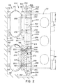
- FIG. 2 is a partial cross-sectional view of one of the sand knock-out head clamping assemblies of FIG. 1 .
- FIG. 3 is a perspective view of one of the sand knock-out head clamping assemblies of FIG. 1 .
- FIG. 4 is a partial exploded view of the assembly of FIG. 3 .
- FIG. 5 is a perspective view of an exemplary insert of the assembly of FIG. 3 .
- FIG. 6 is a partial cross-sectional view of the vibrating apparatus of FIG. 1 with a known pad for engaging the casting to be vibrated.
- FIG. 1 illustrates a vibrating apparatus 100 for vibrating at least one casting 102 , such as the depicted cylinder heads for V-6 engine blocks, mounted thereto during a casting process.
- the vibrating apparatus 100 includes a frame 104 and a vibrating mechanism 106 mounted to the frame 104 and operable to vibrate the casting.
- the frame 104 can include a base member 110 , a pair of uprights or vertical supports 112 , 114 secured to opposed end portions 116 , 118 of the base member 110 , and a central upright or support 120 .
- each support 112 , 114 is a pair of spaced clamping members 126 , 128 configured to engage the casting 102 .
- Each clamping member 126 , 128 can be selectively vertically positioned on their respective support 112 , 114 which allows for different sized castings 102 to be mounted to the vibrating apparatus 100 .
- the vibrating mechanism 106 may be realized by various forms, and in the depicted apparatus 100 , includes plate springs 136 mounted at the end portions 116 , 118 of the base member 110 , the plate springs 136 elevating the frame 104 from a supporting surface 138 .
- a vibrating device (not shown) is operably connected to the base member 110 and actuation of the vibrating device imparts vibrations to the base member.
- the vibrating mechanism 106 further includes a pair of pneumatic hammers or bellows 140 , 142 mounted to opposite sides 144 , 146 of the central support 120 .
- the bellows 140 , 142 are selectively expandable by way of pressurized air flowing into the central support 120 via air lines 150 , 152 .
- each bellow 140 is sandwiched between support plates 156 , 158 , with support plates 156 being fastened to the central support.
- each bellow 142 is sandwiched between support plates 160 , 162 , with support plate 160 being fastened to the central support 120 .
- FIG. 6 depicts the vibrating apparatus 100 with a known pad 170 interposed between the casting 102 and the support plates 158 , 162 for holding pressure against the casting 102 as the vibrating mechanism 106 shakes the casting 102 to remove sand remained in the casting process.
- the pad 170 includes a body 172 having a first surface 174 and a second surface 176 opposite the first surface.
- the first surface 174 is in direct contact with the casting 102 .
- the second surface 176 is in direct contact with the support plates 158 , 162 .
- a plurality of mounting holes 180 extend through the body 172 of the pad 170 .
- Each of the mounting holes 180 is provided with a counterbore 182 located on each of the first and second surfaces 174 , 176 .
- the pad 170 is attached to the support plates 156 , 162 by fasteners 186 , such as the depicted bolts, which extend through corresponding mounting holes 190 provided on the supports 158 , 162 and the mounting holes 180 of the pad 170 .
- An end of each fastener 186 is secured to a nut 194 located in the counterbore 182 , which ensures that the casting 102 is not damaged by the nuts during operation of the vibrating apparatus 100 .
- each of the first and second surfaces 174 , 176 of the pad 170 can become damaged and/or worn during shaking of the casting 102 by the vibrating mechanism 106 .
- the pad 170 cannot be turned and must be discarded.
- the present disclosure is directed to a sand knock-out head clamping assembly 200 to be used with the vibrating apparatus 100 for engaging the casting 102 instead of the known pad 170 .
- the assembly 200 comprises a holder 202 configured to be releasably mounted to the associated vibratory mechanism 106 and an insert or pad 204 removably mounted only to the holder 202 .
- the holder 202 can be formed from aluminum/aluminum alloy and the insert 204 can be formed from a nylon material.
- the holder 202 includes a body 210 having a first face 212 and a second face 214 opposite the first face.
- the body 210 further includes a first sidewall 216 and a second sidewall 218 opposite the first sidewall, the first and second sidewalls extending along a length of the body 210 .
- the first face 212 of each holder 210 mounted to the vibrating apparatus 100 is in contact with the vibratory mechanism 106 , and particularly, is in direct contact with the support plates 158 , 160 .
- the holder body 210 includes a plurality of mounting holes 226 extending therethrough. Each of the mounting holes 226 is provided with a counterbore 228 located on the second face 214 .
- the mounting holes 226 are dimensioned to receive fasteners 230 , such as the depicted bolts, which fasten the holder to the support plates 158 , 160 of the vibrating mechanism 106 .
- the fasteners 230 extend through the mounting holes 190 provided on the support plates 158 , 162 and the mounting holes 226 of the holder 202 .
- An end of each fastener 230 is secured to a nut 232 located in the counterbore 228 , which ensures that the insert 204 is not damaged by the fasteners and/or nuts during operation of the vibrating apparatus 100 .
- the fasteners may be any type of mechanical fastening devices commonly known in the art so long as an end of the fastener does not engage the insert 204 .
- the holder body 210 includes an engagement member 240 extending outwardly from the second face 214 opposite the connection of the holder body 210 to the vibrating mechanism 106 .
- the insert 204 is configured to at least partially receive the engagement member 240 .
- the engagement member 240 can include a first flange structure 242 located adjacent the first sidewall 216 of the holder body 210 .
- the first flange structure 242 can extend approximately an entire length of the first sidewall 216 and includes a first section 250 extending perpendicularly from the second face 214 of the holder body 210 and a second section 252 extending perpendicularly from the first section 250 .
- the engagement member 240 can also include a second flange structure 244 located adjacent the second sidewall 218 of the holder body 210 . Similar to the first flange structure, the second flange structure 244 can extend approximately an entire length of the second sidewall 218 of the holder body 210 and includes a first section 258 extending perpendicularly from the second face 214 of the holder body 210 and a second section 260 extending perpendicularly from the first section 258 . According to one aspect, the first flange structure 242 is L-shaped, and the second section 252 extends toward the second sidewall 218 of the holder body 210 .
- the second flange structure 244 is also L-shaped, and the second section 260 extends toward the first sidewall 216 of the holder body 210 .
- first and second flange structures 242 , 244 are contemplated.
- each of the first and second flange structures can include a single section extending outwardly from the second face 214 and canted toward the other flange structure.
- the insert 204 is removably mounted only to the holder 202 and is dimensioned to be slidingly received between the first and second flange structures 242 , 244 .
- the insert 204 includes an insert body 270 having a first surface 272 and a second surface 274 opposite the first surface, and one of the first and second surfaces 272 , 274 directly contacts or engages the casting 102 .
- the insert body 270 further includes a first side 276 and a second side 278 opposite the first side, each side being configured to engage the first and second flange structures 242 , 244 of the holder 202 .
- the first side 276 is configured to at least partially receive one of the first and second flange structures 242 , 244 of the holder 202 and the second side 278 is configured to receive the other of the first and second flange structures 242 , 244 .
- the first side 276 of the insert body 270 includes an elongated channel 280 extending approximately an entire length of the first side
- the second side 278 of the insert body includes a second elongated channel 282 extending approximately an entire length of the second side.
- Each of the channels 280 , 282 can be centered with respect to the first and second sides 276 , 278 and is dimensioned to at least partially receive one of the first and second flange structures 242 , 244 of the holder body 210 . Particularly, each of the channels 280 , 282 is dimensioned to slidingly receive the second section 252 of the first flange structure 242 . Each of the channels 280 , 282 is also dimensioned to slidingly receive the second section 260 of the second flange structure 244 . This allows the insert 204 to be flipped and/or rotated in the holder 202 upon wear of one of the first and second surface 272 , 274 .
- the insert 204 is configured to have a first mounting position on the holder 202 where the first surface 272 engages the casting 102 and a second mounting position on the holder 202 where the second surface 274 engages the casting.
- the insert body 270 can also include a plurality of apertures 286 extending therethrough. Once inserted into the holder 202 , the apertures 286 of the insert 204 are aligned with the plurality of mounting holes 226 of the holder body 210 , and the apertures 286 allow for inspecting of the fasteners 230 .
- the holder 202 and insert 204 are configured such that the fasteners 230 do not directly contact or engage the insert.
- the holder 202 includes a lower shelf 290 for supporting one of a bottom wall 292 or a top wall 302 of the insert body 270 .
- the insert body 270 can include chamfered corners; although, this is not required.
- a retainer 296 is provided for engaging both a top wall 300 of the holder body 210 and the top wall 302 of the insert body 270 .
- the retainer 296 is mounted only to the top wall 300 of the holder body 210 and can include a pair of fasteners 306 which extend through washers 310 and threadingly engage holes 312 provided on the top wall 300 .
- the present assembly 200 is only provided with the retainer 296 which allows for ease of insert 204 removal and/or replacement from the holder 202 .
Landscapes
- Engineering & Computer Science (AREA)
- Mechanical Engineering (AREA)
- Casting Devices For Molds (AREA)
Abstract
Description
Claims (20)
Priority Applications (1)
| Application Number | Priority Date | Filing Date | Title |
|---|---|---|---|
| US14/244,989 US9272329B2 (en) | 2014-04-04 | 2014-04-04 | Sand knock-out head clamping assembly |
Applications Claiming Priority (1)
| Application Number | Priority Date | Filing Date | Title |
|---|---|---|---|
| US14/244,989 US9272329B2 (en) | 2014-04-04 | 2014-04-04 | Sand knock-out head clamping assembly |
Publications (2)
| Publication Number | Publication Date |
|---|---|
| US20150283608A1 US20150283608A1 (en) | 2015-10-08 |
| US9272329B2 true US9272329B2 (en) | 2016-03-01 |
Family
ID=54208924
Family Applications (1)
| Application Number | Title | Priority Date | Filing Date |
|---|---|---|---|
| US14/244,989 Expired - Fee Related US9272329B2 (en) | 2014-04-04 | 2014-04-04 | Sand knock-out head clamping assembly |
Country Status (1)
| Country | Link |
|---|---|
| US (1) | US9272329B2 (en) |
Families Citing this family (1)
| Publication number | Priority date | Publication date | Assignee | Title |
|---|---|---|---|---|
| CN111957928B (en) * | 2020-08-31 | 2021-04-02 | 江西维海机械设备有限公司 | Precoated sand casting method for large casting |
Citations (9)
| Publication number | Priority date | Publication date | Assignee | Title |
|---|---|---|---|---|
| GB562442A (en) | 1943-03-15 | 1944-07-03 | Hopkinsons Ltd | Improvements in foundry moulding machines |
| DE3239262A1 (en) | 1982-10-23 | 1984-04-26 | Alb. Klein Gmbh & Co Kg, 5241 Niederfischbach | Method and device for decoring castings |
| EP0493999A1 (en) | 1990-12-19 | 1992-07-08 | Automobiles Peugeot | Apparatus for removing sand from castings |
| US5213150A (en) * | 1990-11-07 | 1993-05-25 | Doehler-Jarvis Limited Partnership | Core knock-out fixture |
| JPH07308751A (en) | 1994-05-20 | 1995-11-28 | Aisin Takaoka Ltd | Method for removing residual foreign matter in inner part of hollow casting |
| JPH08174191A (en) * | 1994-12-26 | 1996-07-09 | Daihatsu Motor Co Ltd | Device for shaking out sand from casting |
| US6644382B1 (en) | 1997-12-13 | 2003-11-11 | Yoshitaka Aoyama | Casting sand shake-out method and its apparatus |
| JP2010064082A (en) | 2008-09-09 | 2010-03-25 | Sintokogio Ltd | Core sand shake-out apparatus for casting |
| US20130014909A1 (en) * | 2011-07-12 | 2013-01-17 | Sintokogio, Ltd. | Method and apparatus for loosening a jacket |
-
2014
- 2014-04-04 US US14/244,989 patent/US9272329B2/en not_active Expired - Fee Related
Patent Citations (9)
| Publication number | Priority date | Publication date | Assignee | Title |
|---|---|---|---|---|
| GB562442A (en) | 1943-03-15 | 1944-07-03 | Hopkinsons Ltd | Improvements in foundry moulding machines |
| DE3239262A1 (en) | 1982-10-23 | 1984-04-26 | Alb. Klein Gmbh & Co Kg, 5241 Niederfischbach | Method and device for decoring castings |
| US5213150A (en) * | 1990-11-07 | 1993-05-25 | Doehler-Jarvis Limited Partnership | Core knock-out fixture |
| EP0493999A1 (en) | 1990-12-19 | 1992-07-08 | Automobiles Peugeot | Apparatus for removing sand from castings |
| JPH07308751A (en) | 1994-05-20 | 1995-11-28 | Aisin Takaoka Ltd | Method for removing residual foreign matter in inner part of hollow casting |
| JPH08174191A (en) * | 1994-12-26 | 1996-07-09 | Daihatsu Motor Co Ltd | Device for shaking out sand from casting |
| US6644382B1 (en) | 1997-12-13 | 2003-11-11 | Yoshitaka Aoyama | Casting sand shake-out method and its apparatus |
| JP2010064082A (en) | 2008-09-09 | 2010-03-25 | Sintokogio Ltd | Core sand shake-out apparatus for casting |
| US20130014909A1 (en) * | 2011-07-12 | 2013-01-17 | Sintokogio, Ltd. | Method and apparatus for loosening a jacket |
Also Published As
| Publication number | Publication date |
|---|---|
| US20150283608A1 (en) | 2015-10-08 |
Similar Documents
| Publication | Publication Date | Title |
|---|---|---|
| CN101330997A (en) | Vibration shakeout device | |
| US9272329B2 (en) | Sand knock-out head clamping assembly | |
| CN111546226B (en) | Casing cavity/oil path vibration polishing device | |
| JP2019217525A (en) | Workpiece support device for casting sand removal | |
| JP5126019B2 (en) | Vibration welding equipment | |
| CN103842114A (en) | Universal boxing device for casting molds and general boxing method for casting molds using the same | |
| US10081051B2 (en) | Variable method for using cloth filters in automated vertical molding | |
| JPH07308751A (en) | Method for removing residual foreign matter in inner part of hollow casting | |
| JPH04172170A (en) | Device for collapsing and removing sand core in casting by vibration | |
| US3584419A (en) | Apparatus and method for cleaning hollow castings | |
| US1855474A (en) | Flask shake-out | |
| JP4844888B2 (en) | Cast jig sand removal jig member | |
| CN212703960U (en) | High-efficient mould of arranging waste material | |
| JP3806682B2 (en) | Casting frame demolition equipment | |
| JP2012050990A (en) | Vibrating sand shaking-out apparatus | |
| KR20140121111A (en) | The base mold sand mold for manufacturing device | |
| US9481030B2 (en) | Foundry cloth filter setter for vertical mold machines | |
| JP4468742B2 (en) | Casting out method | |
| US7922476B2 (en) | Device for the production of confectionery | |
| JP5603824B2 (en) | Mobility aid | |
| CN104907544A (en) | A shakeout machine table of a multi-dimensional vibration shakeout machine for casting | |
| CN111822597A (en) | Stamping dies that can quickly adjust the effective length of the punch | |
| CN222588091U (en) | Adjustable vibration shakeout machine | |
| US1774612A (en) | Vibrator | |
| JP2591052Y2 (en) | Deburring device |
Legal Events
| Date | Code | Title | Description |
|---|---|---|---|
| AS | Assignment |
Owner name: HONDA MOTOR CO., LTD., JAPAN Free format text: ASSIGNMENT OF ASSIGNORS INTEREST;ASSIGNORS:RADKE, KRISTOPHER;HAVENS, JEFFREY S.;SIGNING DATES FROM 20140325 TO 20140326;REEL/FRAME:032601/0055 |
|
| ZAAA | Notice of allowance and fees due |
Free format text: ORIGINAL CODE: NOA |
|
| ZAAB | Notice of allowance mailed |
Free format text: ORIGINAL CODE: MN/=. |
|
| STCF | Information on status: patent grant |
Free format text: PATENTED CASE |
|
| MAFP | Maintenance fee payment |
Free format text: PAYMENT OF MAINTENANCE FEE, 4TH YEAR, LARGE ENTITY (ORIGINAL EVENT CODE: M1551); ENTITY STATUS OF PATENT OWNER: LARGE ENTITY Year of fee payment: 4 |
|
| FEPP | Fee payment procedure |
Free format text: MAINTENANCE FEE REMINDER MAILED (ORIGINAL EVENT CODE: REM.); ENTITY STATUS OF PATENT OWNER: LARGE ENTITY |
|
| LAPS | Lapse for failure to pay maintenance fees |
Free format text: PATENT EXPIRED FOR FAILURE TO PAY MAINTENANCE FEES (ORIGINAL EVENT CODE: EXP.); ENTITY STATUS OF PATENT OWNER: LARGE ENTITY |
|
| STCH | Information on status: patent discontinuation |
Free format text: PATENT EXPIRED DUE TO NONPAYMENT OF MAINTENANCE FEES UNDER 37 CFR 1.362 |
|
| FP | Lapsed due to failure to pay maintenance fee |
Effective date: 20240301 |