US926848A - Carbureter. - Google Patents
Carbureter. Download PDFInfo
- Publication number
- US926848A US926848A US1908423571A US926848A US 926848 A US926848 A US 926848A US 1908423571 A US1908423571 A US 1908423571A US 926848 A US926848 A US 926848A
- Authority
- US
- United States
- Prior art keywords
- valve
- housing
- oil
- air
- lever
- Prior art date
- Legal status (The legal status is an assumption and is not a legal conclusion. Google has not performed a legal analysis and makes no representation as to the accuracy of the status listed.)
- Expired - Lifetime
Links
Images
Classifications
-
- F—MECHANICAL ENGINEERING; LIGHTING; HEATING; WEAPONS; BLASTING
- F02—COMBUSTION ENGINES; HOT-GAS OR COMBUSTION-PRODUCT ENGINE PLANTS
- F02M—SUPPLYING COMBUSTION ENGINES IN GENERAL WITH COMBUSTIBLE MIXTURES OR CONSTITUENTS THEREOF
- F02M7/00—Carburettors with means for influencing, e.g. enriching or keeping constant, fuel/air ratio of charge under varying conditions
- F02M7/12—Other installations, with moving parts, for influencing fuel/air ratio, e.g. having valves
- F02M7/22—Other installations, with moving parts, for influencing fuel/air ratio, e.g. having valves fuel flow cross-sectional area being controlled dependent on air-throttle-valve position
-
- Y—GENERAL TAGGING OF NEW TECHNOLOGICAL DEVELOPMENTS; GENERAL TAGGING OF CROSS-SECTIONAL TECHNOLOGIES SPANNING OVER SEVERAL SECTIONS OF THE IPC; TECHNICAL SUBJECTS COVERED BY FORMER USPC CROSS-REFERENCE ART COLLECTIONS [XRACs] AND DIGESTS
- Y10—TECHNICAL SUBJECTS COVERED BY FORMER USPC
- Y10T—TECHNICAL SUBJECTS COVERED BY FORMER US CLASSIFICATION
- Y10T137/00—Fluid handling
- Y10T137/2496—Self-proportioning or correlating systems
- Y10T137/2559—Self-controlled branched flow systems
- Y10T137/2564—Plural inflows
- Y10T137/2572—One inflow supplements another
Definitions
- This invention relates to improvements in carbureters, and has for an object the provision of means that will permit the ready regulation of the flow of oil for varying the amounts of air supplied.
- Another object in view is the provision of a oarbureter having an air valve and an oil valve so 'connected up and mounted asto permit a ready variation of the oil and air without changing the tension of any of the iarts.
- a further object of the invention is the provision of means for re ulating the inflow of oil that will cause the oi valve to open to a greater or less extent, but will permit the usual amount of air to be supplied.
- valve housing 2 indicates a mixing chamber or housing. and 2 the housing of an intake air valve.
- the valve housing 2 may be secured to housing 1 by screw threads or in any other desired manner, and is positioned so as to extend to a right angle to housing 1.
- housing 1 is bent at 3 so that a valve 4 in housing 2 may act freely for permitting air to enter into housing 1 even though housing 2 is ositioned at right angles to housing 1.
- Va ve 4 is normally held closed by a spring 5 of any desired strength and in'operation is opened by suc tion from the engine as the same draws in air and oil.
- Extending fromvvalve 4 is a stem 6 that is pivotally mounted at 7 to a lever 8 which in turn is pivotally mounted at ⁇ 9 to a sliding or adjustable member 10.
- the sliding adjustable member 10 is held in position by any desired securing means as bolt i 1 th at moves in a slot or way 1.2 formed in housing covers the slot 12 so that no air may enter at this place.
- Lever 8 extends beyond pivotal point or member 9 and is pivotally secured at 14 to a valve 15 that is adapted to close an 'oil feed pipe 16.
- Valve 15 is provided with a comparatively long projecting member 17 that acts as a guide for the valve in its movement so that in movin off its seat and moving back to its seat t ere Will be no danger or likelihood of the valve not properly seating itself or leaving any place'for the escape of oil.
- the movement of valve 15 is substantially in a vertical direction, but by reason of the.
- pivots 9 and 14 being positioned in a certain relationship to each other there will be caused a movement slightly on the arc of a circle for the upper end of valve 15, and in order to revent any such movement to cause any ikelihood of the valve missing its seat an extension 17 is provided that is never removed from tube 16 and consequently will guide the valve back properly to its seat.
- valve or baflling member 18 Positioned in housing 1 in the travel of the air and oil as the same goes toward the engine (not shown) is a valve or baflling member 18.
- the valve or balling member 18 is pivotally mounted in housing 1 and is adapted to close one end of housing 1 so that when closed the engine to which the carbureter is attached cannot draw in air or oil.
- the baffling member or valve 18 is adapted to cause a greater or less supply of gas to be fed to the engine by turning the same for partially closing the end of housing 1, as seen in the drawing.
- the housing 1 may be secured to the engine by'securing the same on at 19.
- a suction is created that extends to housing 1 and from there to housing 2 which will open valve 4 and permitan influx of air.V
- valve 4 opens the motion Will be communicated to lever 8 and from thence to valve 15 which will be open atjthe same .time so that when valve 4 .is open air travels from valve 4 llO through housing 1 and picks up the oil from pipe 16 Iand is enriched thereby and is thoroughly mixed by striking against bai-lling member 18 if not already thoroughly mixed. From housing 1 it passes on to the explosion chamber of the engine and acts in the usual manner.
- a housing formed with a slot therein, an air valve, an oil valve, a lever connectin said valves, an adjustable fulcrum for said ever, a sliding late for closing said slot in said housing, an means passing through said slot and engaging said plate for locking said plate and said fulcrum in their adjusted positions.
- a housing formed with a slot, an-air valve, an oil valve, a lever for operating both of said valves, a slidable fulcrum for said lever, and means passing through said slot for adjustably securmg said fu-lcrum in position.
- a housing formed with a slot in one side, an air valve, an oil valve, a
- lever for connecting said valves, a movable fulcrum for said lever, means passing through said slot in said housing for regulating the osition of said fulcrum, and means for closing said slot regardless of the position of the means passing through the slot.
- a carbureter the combination with a housing, of an air intake valve ositioned in one end of said housing, a ba 'ng member a'nd regulator positioned in the opposite end -of said housing, means for adjusting said baiing member and regulator for varying the amount of mixture drawn from said housing, an oil valve for permitting the admission of oil into said housing for mixing with the air passing in through said air intake valve, a pivotally mounted lever connected to said air valve and said oil valve, means for adjusting the fulcrum point of said lever for varying the ratio of sald air and oil forming the mixture drawn ast said baillin member and regulator, andp means for loc ing said fulcrum point in its adjusted position.
- a housing for moving said valve, an adjustab e fulcrumfor said lever, a set screw passing through said housin for adj ustably clampmg in position said fuIcrum, and an air valve, connected to said lever whereby when said air valve is moved said oil valve will be moved.
Landscapes
- Engineering & Computer Science (AREA)
- Chemical & Material Sciences (AREA)
- Combustion & Propulsion (AREA)
- Mechanical Engineering (AREA)
- General Engineering & Computer Science (AREA)
- Mechanically-Actuated Valves (AREA)
- Lubrication Of Internal Combustion Engines (AREA)
- Control Of The Air-Fuel Ratio Of Carburetors (AREA)
Description
J. A. CARLSON.
CARBURETER.
APPLICATION FILED MAB. 27, 190e.
Patented July 6, 1909.
JOHN A. CARLSON, OF DENVER, COLORADO.
CARBURETER.
Specification of Letters Patent.
Application led March 27, 1908.
Patented July e, 1909.
serial No. 423,571.
To all whom it may concern:
Be it kno n that I, JOHN A. CARLSON, citizen of the I inited States, residing at Denver, in the county of Denver and State of Colorado, have invented certain new and 'useful Improvements in Carbureters: and I do hereby deelare the following to be a full, clear, and exact description of the invention, such as will enablev others skilled in the art to which it appertains to make and use the sam-e.
This invention relates to improvements in carbureters, and has for an object the provision of means that will permit the ready regulation of the flow of oil for varying the amounts of air supplied.
Another object in view is the provision of a oarbureter having an air valve and an oil valve so 'connected up and mounted asto permit a ready variation of the oil and air without changing the tension of any of the iarts. I A further object of the invention is the provision of means for re ulating the inflow of oil that will cause the oi valve to open to a greater or less extent, but will permit the usual amount of air to be supplied.
W ith these and other objects in View the invention comprisescertain novel constructions, combinations, and arrangement of parts as will be hereinafter more fully described and claimed.
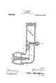
In the accompanying drawing, the figure presents a longitudinal, vertical section through a carburetor, embodying the features of the resent invention.
Referring to the drawing by numerals, 1 indicates a mixing chamber or housing. and 2 the housing of an intake air valve. The valve housing 2 may be secured to housing 1 by screw threads or in any other desired manner, and is positioned so as to extend to a right angle to housing 1. In order to accommodate or receive housing 2 housing 1 is bent at 3 so that a valve 4 in housing 2 may act freely for permitting air to enter into housing 1 even though housing 2 is ositioned at right angles to housing 1. Va ve 4 is normally held closed by a spring 5 of any desired strength and in'operation is opened by suc tion from the engine as the same draws in air and oil. Extending fromvvalve 4 is a stem 6 that is pivotally mounted at 7 to a lever 8 which in turn is pivotally mounted at`9 to a sliding or adjustable member 10. The sliding adjustable member 10 is held in position by any desired securing means as bolt i 1 th at moves in a slot or way 1.2 formed in housing covers the slot 12 so that no air may enter at this place.
Lever 8 extends beyond pivotal point or member 9 and is pivotally secured at 14 to a valve 15 that is adapted to close an 'oil feed pipe 16. Valve 15 is provided with a comparatively long projecting member 17 that acts as a guide for the valve in its movement so that in movin off its seat and moving back to its seat t ere Will be no danger or likelihood of the valve not properly seating itself or leaving any place'for the escape of oil. The movement of valve 15 is substantially in a vertical direction, but by reason of the. pivots 9 and 14 being positioned in a certain relationship to each other there will be caused a movement slightly on the arc of a circle for the upper end of valve 15, and in order to revent any such movement to cause any ikelihood of the valve missing its seat an extension 17 is provided that is never removed from tube 16 and consequently will guide the valve back properly to its seat.
Positioned in housing 1 in the travel of the air and oil as the same goes toward the engine (not shown) is a valve or baflling member 18. The valve or balling member 18 is pivotally mounted in housing 1 and is adapted to close one end of housing 1 so that when closed the engine to which the carbureter is attached cannot draw in air or oil. Ordinarily, however, the baffling member or valve 18 is adapted to cause a greater or less supply of gas to be fed to the engine by turning the same for partially closing the end of housing 1, as seen in the drawing.
In operation the housing 1 may be secured to the engine by'securing the same on at 19. As the engine is turned over a suction is created that extends to housing 1 and from there to housing 2 which will open valve 4 and permitan influx of air.V As valve 4 opens the motion Will be communicated to lever 8 and from thence to valve 15 which will be open atjthe same .time so that when valve 4 .is open air travels from valve 4 llO through housing 1 and picks up the oil from pipe 16 Iand is enriched thereby and is thoroughly mixed by striking against bai-lling member 18 if not already thoroughly mixed. From housing 1 it passes on to the explosion chamber of the engine and acts in the usual manner. If there is not suicient oil being fed through pipe 16 supporting member 10 may be moved longitudinally of housing 1, and consequently pivot 9 will be moved in slot 13 toward pivotal member 7. g This will cause valve 4 to move valve 15 to a greater extent, and Will thereby permit more oil to flow into housing 1. By this construction and arrangement oil and air are fed in at the sametime and no oil is fed when there is no air fed, and in addition by reason of the adjustin member 10 oil and air may be varied until t e right .proportion of airand oil is secured for securlng the best results.
What I claim is:
1. In a carbureter, a housing formed with a slot therein, an air valve, an oil valve, a lever connectin said valves, an adjustable fulcrum for said ever, a sliding late for closing said slot in said housing, an means passing through said slot and engaging said plate for locking said plate and said fulcrum in their adjusted positions.
2. In a carbureter, a housing formed with a slot, an-air valve, an oil valve, a lever for operating both of said valves, a slidable fulcrum for said lever, and means passing through said slot for adjustably securmg said fu-lcrum in position.
3. In a carbureter, a housing formed with a slot in one side, an air valve, an oil valve, a
lever for connecting said valves, a movable fulcrum for said lever, means passing through said slot in said housing for regulating the osition of said fulcrum, and means for closing said slot regardless of the position of the means passing through the slot.
4. In a carbureter, the combination with a housing, of an air intake valve ositioned in one end of said housing, a ba 'ng member a'nd regulator positioned in the opposite end -of said housing, means for adjusting said baiing member and regulator for varying the amount of mixture drawn from said housing, an oil valve for permitting the admission of oil into said housing for mixing with the air passing in through said air intake valve, a pivotally mounted lever connected to said air valve and said oil valve, means for adjusting the fulcrum point of said lever for varying the ratio of sald air and oil forming the mixture drawn ast said baillin member and regulator, andp means for loc ing said fulcrum point in its adjusted position.
5. In a carbureter, a housing, a valve for admitting oil into said housin a lever for moving said valve, an adjustab e fulcrumfor said lever, a set screw passing through said housin for adj ustably clampmg in position said fuIcrum, and an air valve, connected to said lever whereby when said air valve is moved said oil valve will be moved.
In testimony whereof I aix my signature in presence of two Witnesses.
JOHN A. CARLSON. Witnesses:
W. B. SHATTEN, ISABEL M. STRONG.
Priority Applications (1)
| Application Number | Priority Date | Filing Date | Title |
|---|---|---|---|
| US1908423571 US926848A (en) | 1908-03-27 | 1908-03-27 | Carbureter. |
Applications Claiming Priority (1)
| Application Number | Priority Date | Filing Date | Title |
|---|---|---|---|
| US1908423571 US926848A (en) | 1908-03-27 | 1908-03-27 | Carbureter. |
Publications (1)
| Publication Number | Publication Date |
|---|---|
| US926848A true US926848A (en) | 1909-07-06 |
Family
ID=2995274
Family Applications (1)
| Application Number | Title | Priority Date | Filing Date |
|---|---|---|---|
| US1908423571 Expired - Lifetime US926848A (en) | 1908-03-27 | 1908-03-27 | Carbureter. |
Country Status (1)
| Country | Link |
|---|---|
| US (1) | US926848A (en) |
Cited By (1)
| Publication number | Priority date | Publication date | Assignee | Title |
|---|---|---|---|---|
| US20050034758A1 (en) * | 2003-07-03 | 2005-02-17 | Dan Bron | Proportioner |
-
1908
- 1908-03-27 US US1908423571 patent/US926848A/en not_active Expired - Lifetime
Cited By (2)
| Publication number | Priority date | Publication date | Assignee | Title |
|---|---|---|---|---|
| US20050034758A1 (en) * | 2003-07-03 | 2005-02-17 | Dan Bron | Proportioner |
| US7185669B2 (en) * | 2003-07-03 | 2007-03-06 | Dan Bron | Proportioner |
Similar Documents
| Publication | Publication Date | Title |
|---|---|---|
| US926848A (en) | Carbureter. | |
| US3214150A (en) | Carburetor | |
| US1506166A (en) | Regulation of the combustible mixture in internal-combustion engines | |
| US1161437A (en) | Carbureter. | |
| US1214322A (en) | Engine attachment. | |
| US1063866A (en) | Fuel-feed regulator for explosive-engines. | |
| US917125A (en) | Carbureter. | |
| US1632198A (en) | Carburetor | |
| US1204247A (en) | Carbureter. | |
| US1186166A (en) | Carbureter. | |
| US1022326A (en) | Carbureter. | |
| US927529A (en) | Carbureter. | |
| US1213639A (en) | Mechanism for simultaneously operating two rock-shafts. | |
| US1045251A (en) | Carbureter. | |
| US946632A (en) | Carbureter. | |
| US1159029A (en) | Carbureter. | |
| US1304374A (en) | William benjamin robeson | |
| US1102085A (en) | Governor for gas-engines. | |
| US1029899A (en) | Throttle for carbureters. | |
| USRE13784E (en) | Caububeteb | |
| US1214457A (en) | Automatic adjustable feeder-valve. | |
| US1111179A (en) | Carbureter. | |
| US1901191A (en) | Gas and air mixer for hydrocarbon engines | |
| US1329608A (en) | Auxiliary air-inlet valve | |
| US792628A (en) | Carbureter for gas-engines. |