US9260644B2 - Heat transfer system with aqueous heat transfer fluid - Google Patents

Heat transfer system with aqueous heat transfer fluid Download PDF

Info

Publication number
US9260644B2
US9260644B2 US13/855,378 US201313855378A US9260644B2 US 9260644 B2 US9260644 B2 US 9260644B2 US 201313855378 A US201313855378 A US 201313855378A US 9260644 B2 US9260644 B2 US 9260644B2
Authority
US
United States
Prior art keywords
heat transfer
transfer fluid
acid
sodium
carboxylic acid
Prior art date
Legal status (The legal status is an assumption and is not a legal conclusion. Google has not performed a legal analysis and makes no representation as to the accuracy of the status listed.)
Active, expires
Application number
US13/855,378
Other versions
US20140290912A1 (en
Inventor
John W. Steele
Daniel Montefusco
Barbara M. Peyton
Jerome D. Varsik
Current Assignee (The listed assignees may be inaccurate. Google has not performed a legal analysis and makes no representation or warranty as to the accuracy of the list.)
Hamilton Sundstrand Space System International Inc
Original Assignee
Hamilton Sundstrand Space System International Inc
Priority date (The priority date is an assumption and is not a legal conclusion. Google has not performed a legal analysis and makes no representation as to the accuracy of the date listed.)
Filing date
Publication date
Application filed by Hamilton Sundstrand Space System International Inc filed Critical Hamilton Sundstrand Space System International Inc
Priority to US13/855,378 priority Critical patent/US9260644B2/en
Assigned to HAMILTON SUNDSTRAND SPACE SYSTEMS INTERNATIONAL, INC. reassignment HAMILTON SUNDSTRAND SPACE SYSTEMS INTERNATIONAL, INC. ASSIGNMENT OF ASSIGNORS INTEREST (SEE DOCUMENT FOR DETAILS). Assignors: PEYTON, BARBARA M., MONTEFUSCO, DANIEL, Varsik, Jerome D., STEELE, JOHN W.
Publication of US20140290912A1 publication Critical patent/US20140290912A1/en
Application granted granted Critical
Publication of US9260644B2 publication Critical patent/US9260644B2/en
Active legal-status Critical Current
Adjusted expiration legal-status Critical

Links

Images

Classifications

    • CCHEMISTRY; METALLURGY
    • C09DYES; PAINTS; POLISHES; NATURAL RESINS; ADHESIVES; COMPOSITIONS NOT OTHERWISE PROVIDED FOR; APPLICATIONS OF MATERIALS NOT OTHERWISE PROVIDED FOR
    • C09KMATERIALS FOR MISCELLANEOUS APPLICATIONS, NOT PROVIDED FOR ELSEWHERE
    • C09K5/00Heat-transfer, heat-exchange or heat-storage materials, e.g. refrigerants; Materials for the production of heat or cold by chemical reactions other than by combustion
    • C09K5/08Materials not undergoing a change of physical state when used
    • C09K5/10Liquid materials
    • CCHEMISTRY; METALLURGY
    • C23COATING METALLIC MATERIAL; COATING MATERIAL WITH METALLIC MATERIAL; CHEMICAL SURFACE TREATMENT; DIFFUSION TREATMENT OF METALLIC MATERIAL; COATING BY VACUUM EVAPORATION, BY SPUTTERING, BY ION IMPLANTATION OR BY CHEMICAL VAPOUR DEPOSITION, IN GENERAL; INHIBITING CORROSION OF METALLIC MATERIAL OR INCRUSTATION IN GENERAL
    • C23FNON-MECHANICAL REMOVAL OF METALLIC MATERIAL FROM SURFACE; INHIBITING CORROSION OF METALLIC MATERIAL OR INCRUSTATION IN GENERAL; MULTI-STEP PROCESSES FOR SURFACE TREATMENT OF METALLIC MATERIAL INVOLVING AT LEAST ONE PROCESS PROVIDED FOR IN CLASS C23 AND AT LEAST ONE PROCESS COVERED BY SUBCLASS C21D OR C22F OR CLASS C25
    • C23F11/00Inhibiting corrosion of metallic material by applying inhibitors to the surface in danger of corrosion or adding them to the corrosive agent
    • C23F11/08Inhibiting corrosion of metallic material by applying inhibitors to the surface in danger of corrosion or adding them to the corrosive agent in other liquids
    • FMECHANICAL ENGINEERING; LIGHTING; HEATING; WEAPONS; BLASTING
    • F28HEAT EXCHANGE IN GENERAL
    • F28DHEAT-EXCHANGE APPARATUS, NOT PROVIDED FOR IN ANOTHER SUBCLASS, IN WHICH THE HEAT-EXCHANGE MEDIA DO NOT COME INTO DIRECT CONTACT
    • F28D15/00Heat-exchange apparatus with the intermediate heat-transfer medium in closed tubes passing into or through the conduit walls ; Heat-exchange apparatus employing intermediate heat-transfer medium or bodies

Definitions

  • the subject matter disclosed herein generally relates to heat transfer systems and, more particularly, to heat transfer systems that include an aluminum surface in contact with a heat transfer fluid.
  • Heat transfer systems are widely used in various applications, including but not limited to heat transfer systems for environmental heating and cooling in aerospace applications, automotive, industrial, residential, and electronics, to name a few. Heat transfer systems often utilize a heat transfer fluid that circulates between two or more heat exchangers to transfer heat between environmental spaces. Many such heat transfer systems include one or more aluminum components in contact with the heat transfer fluid. Aluminum alloys offer durability, malleability, high strength to weight ratio, and thermal conductivity, which make it a desirable material for heat transfer system components such as heat exchangers, tubes, fins, etc.
  • heat transfer fluids have been used or proposed for use in various types of heat transfer systems.
  • Organic liquids such as halogenated hydrocarbons (e.g., R-134a (tetrafluoroethane), R-1234 (tetrafluoropropene)) have been used in many systems.
  • halogenated hydrocarbons e.g., R-134a (tetrafluoroethane), R-1234 (tetrafluoropropene)
  • R-134a tetrafluoroethane
  • R-1234 tetrafluoropropene
  • Aqueous-based heat transfer fluids containing glycols such as propylene glycol have also been used.
  • Such fluids can provide benefits over organic liquids with respect to toxicity, flammability, thermal performance and environmental issues. However, they are not suitable for some heat transfer systems, especially those with a high surface area of aluminum, where corrosion becomes a challenge.
  • propylene glycol acts to reduce the freezing point temperature of the heat transfer fluid.
  • PCM phase change material
  • the latent heat of a phase change material is used to store and release thermal energy
  • the freezing point suppression imparted by the glycol to an aqueous heat fluid can be problematic.
  • the glycol may have a detrimental effect on the surface active properties of the coolant needed for proper capillary action.
  • the use of aqueous based coolants results in a need to control microbial growth.
  • a heat transfer system comprises a heat transfer fluid circulation loop.
  • the heat transfer system includes a heat exchanger disposed in the heat transfer fluid circulation loop.
  • the heat transfer fluid is an aqueous solution having a pH of 7.8 to 8.0 that comprises from 1.00 wt. % to 1.20 wt. % of a buffer composition comprising sodium and/or potassium salts of borate, carbonate, and bicarbonate, from 0.40 wt. % to 0.60 wt. % of a straight chain aliphatic dicarboxylic acid, from 0.90 wt. % to 1.10 wt. % of a branched aliphatic carboxylic acid, from 0.40 wt. % to 0.60 wt.
  • a method of operating a heat transfer system comprises circulating a heat transfer fluid through a heat exchanger disposed in a heat transfer circulation loop, wherein the heat transfer fluid is an aqueous solution having a pH of 7.8 to 8.0 that comprises from 1.00 wt. % to 1.20 wt. % of a buffer composition comprising sodium and/or potassium salts of borate, carbonate, and bicarbonate, from 0.40 wt. % to 0.60 wt. % of a straight chain aliphatic dicarboxylic acid, from 0.90 wt. % to 1.10 wt. % of a branched aliphatic carboxylic acid, from 0.40 wt.
  • a heat transfer fluid comprises, in an aqueous solution having a pH of 7.8 to 8.0, from 1.00 wt. % to 1.20 wt. % of a buffer composition comprising sodium and/or potassium borate, sodium carbonate, and sodium bicarbonate, from 0.40 wt. % to 0.60 wt. % of a straight chain aliphatic dicarboxylic acid, from 0.90 wt. % to 1.10 wt. % of a branched aliphatic carboxylic acid, from 0.40 wt. % to 0.60 wt. % of an aromatic carboxylic acid, from 0.04 wt. % to 0.08 wt. % of a molybdate salt, and from 0.01 wt. % to 0.03 wt. % of an aldehyde biocide, based on the total weight of the heat transfer fluid.
  • the FIGURE depicts a schematic diagram of an exemplary heat transfer system.
  • heat exchange system 10 includes heat source 12 , pump 14 , heat exchanger 16 , flow control means 18 and fluid reservoir 20 .
  • pump 14 pumps fluid through heat exchange system 10 .
  • the flow of fluid through heat exchange system 10 is controlled by pump 14 and flow control means 18 .
  • Fluid is added to or removed from heat exchange system 10 via fluid reservoir 20 .
  • Heat exchanger 16 is a cooling type heat exchanger for cooling the fluid in heat exchange system 10 .
  • Heat exchanger 16 is in fluid communication with coolant loop 22 .
  • heat exchange system 10 such as pump 14 , heat exchanger 16 , flow control means 18 or coolant loop 22 contain surfaces having high aluminum and/or nickel surface areas.
  • the component surfaces are subject to corrosion and the aforementioned problems when conventional aqueous-based coolants are used.
  • heat exchange system 10 contains the aqueous-based coolant described above.
  • the heat transfer system includes at least one aluminum surface in contact with the heat transfer fluid.
  • Aluminum refers to pure aluminum as well as aluminum alloys (e.g., alloys in which aluminum is the predominant metal). Depending on the temperature and specific function of a component or system that requires heating or cooling, the component or system may contain surfaces with large amounts of aluminum.
  • the benefits of aluminum allow for size and/or weight reduction compared to other materials.
  • aluminum microchannel heat exchangers can be used as an alternative to conventional heat exchangers, and can provide beneficial size, weight, and heat transfer efficiency.
  • Microchannel heat exchangers typically provide small clearances between component surfaces and small gaps in coolant flow paths.
  • gaps between fins can be as low as about 0.5 mm (0.020 inches), while cold plates can have gaps as low as about 0.6 mm (0.025 inches).
  • Flow control valves can have gaps as small as about 0.3 mm (0.012 inches), and pumps can have clearances between the bushing and shaft between about 0.025 mm (0.001 inches) and about 0.04 mm (0.0015 inches). These clearances and gaps can be sensitive to coolant precipitates and aluminum corrosion products. Precipitates within the aqueous-based coolant and dislodged corrosion products can block these small gaps to impede, restrict or block coolant flow.
  • Various components in the heat transfer system can have aluminum surfaces in contact with the heat transfer fluid, including but not limited to cold plates, heat exchangers, and/or heat transfer fluid flow conduits.
  • Heat exchangers can themselves include various sub-components such as manifolds, heat transfer fluid flow tubes or channels, and fins in thermal contact with the heat transfer fluid flow tubes or channels. Any of the above components can be include aluminum surfaces in contact with the heat transfer fluid.
  • the listed components are exemplary, and the system can contain other aluminum components in contact with the heat transfer fluid.
  • the heat transfer systems described herein can have significant amounts of aluminum surface area.
  • the ratio of aluminum surface area to coolant volume ratio is greater than or equal to 1.0 cm 2 aluminum surface area per mL of coolant, more specifically greater than or equal to 2.0 cm 2 aluminum surface area per mL of coolant, and even more specifically greater than or equal to 4.0 cm 2 aluminum surface area per mL of coolant.
  • the aluminum surface area to coolant volume ratio is about 4.7 cm 2 aluminum surface area per mL of coolant (12 square inches per cubic inch) in a flowing system and 34.6 cm 2 /mL (88 square inches per cubic inch) in a static condition.
  • Such levels of aluminum in the system can create particularly onerous demands on heat transfer fluid performance with respect to corrosion resistance.
  • aqueous-based coolant Due to the high aluminum surface area, some commonly used additives can be omitted from the aqueous-based coolant. For example, materials such as copper and carbon steel are not routinely used in applications such as spacecraft applications, with aluminum often used instead. Therefore, the aqueous-based coolant does not need to contain additives that specifically inhibit corrosion of these materials. The omission of these additives removes their potential unwanted effects from the aqueous-based coolant. For instance, azoles and nitrites can potentially be detrimental to surfaces in some spacecraft applications. Azole/organic acid reaction products can contribute to the fouling of filters used in heat transfer systems.
  • Nitrites can reduce to ammonia and shift the pH of the aqueous-based coolant above its effective range in systems having high aluminum surface area, which can also cause the coolant to react negatively with aluminum surfaces.
  • the aqueous-based coolant is free of azoles and nitrites.
  • the pH of the solution is maintained in the range of 7.8 to 8.0, more specifically at about 7.9.
  • the target pH can be achieved with a combination of an appropriate amount of base such as potassium hydroxide in combination with a buffer composition.
  • the buffer composition comprises sodium and/or potassium salts of borate, carbonate, and bicarbonate in amounts ranging from 1.00 wt. % to 1.20 wt. % more specifically from 1.09.% to 1.12 wt. %, based on the total weight of the heat transfer fluid.
  • the relative proportion of the components of the buffer composition can be optimized based on solubility in the working range of the desired coolant and corrosion inhibition needs.
  • the buffer comprises sodium borate, sodium carbonate, and sodium bicarbonate.
  • the heat transfer fluid comprises from 0.10 wt. % to 0.40 wt. % and more specifically from 0.20 wt. % to 0.28 wt. % of sodium borate, from 0.10 wt. % to 0.40 wt. % and more specifically from 0.19 wt. % to 0.27 wt. % of sodium carbonate, and from 0.40 wt. % to 0.80 wt. % and more specifically from 0.58 wt. % to 0.66 wt. % of sodium bicarbonate, based on the total weight of the heat transfer fluid.
  • the buffer composition comprises from 0.20 wt. % to 0.28 wt.
  • the heat transfer fluid comprises a mixture of organic acids, more specifically from 0.40 wt. % to 0.60 wt. % of a straight chain aliphatic dicarboxylic acid, from 0.90 wt. % to 1.10 wt. % of a branched aliphatic carboxylic acid, and from 0.40 wt. % to 0.60 wt. % of an aromatic carboxylic acid.
  • the heat transfer fluid comprises from 0.45 wt. % to 0.55 wt. % of a straight chain aliphatic dicarboxylic acid, from 0.95 wt. % to 1.05 wt.
  • straight chain aliphatic dicarboxylic acids include C 8 -C 12 dicarboxylic acids such as suberic acid, azeleic acid, sebacic acid, and dodecanedioic acid. In a more specific embodiment, the straight chain dicarboxylic acid is sebacic acid.
  • branched aliphatic carboxylic acids include C 6 -C 10 monocarboxylic acids having at least one branch therein, such as 2-ethylhexanoic acid, 3-ethyl-6-methylcotanedioic acid, 4-methyl pentanoic acid, and 2,3-dimethylhexanoic acid.
  • aromatic carboxylic acids include benzoic acid, benzoyl acid, phthaloyl acid, and phthalic acid
  • the heat transfer fluid also includes from 0.04 wt. % to 0.08 wt. % of a molybdate salt, more specifically from 0.055 wt. % to 0.065 wt. % of a molybdate salt.
  • Molybdate salts contain an oxoanion of molybdenum in its highest oxidation state of 6.
  • Molybdate oxoanions can be provided in solution by alkali metal molybdates, alkali earth molybdates, ammonium molybdate and organic molybdate compounds.
  • An exemplary source of molybdate salt is sodium molybdate.
  • Sodium molybdate is a non-oxidizing anodic inhibitor having the molecular formula Na 2 MoO 4 .
  • Sodium molybdate is often found as a dihydrate (Na 2 MoO 4 .2H 2 O).
  • the heat transfer fluid also includes from 0.01 wt. % to 0.03 wt. % of an aldehyde biocide, more specifically from 0.015 wt. % to 0.025 wt. % of an aldehyde biocide.
  • an aldehyde biocide Virtually any aldehyde capable of being dissolved in the solution can function as a biocide.
  • aldehyde biocides include glutaraldehyde and ortho-phthaldehyde.
  • the aldehyde biocide is ortho-phthaldehyde.
  • the heat transfer system described herein can be used, for example, to condition air in an interior space by either transferring heat from the interior space to an outside environment or by transferring heat from an outside environment to the conditioned interior space, and as used herein, the terms “coolant” and “refrigerant” are used interchangeably with the term “heat transfer fluid”, which may be used for either heating or cooling a conditioned space.
  • the conditioned interior space can be a sealed interior space such as a space vehicle, submarine, or other hermetically sealed environment.
  • a portion of the heat transfer fluid in the system is in a frozen state.
  • a 1500 ml volume of the above solution was tested for stability over a 60-day period by initially increasing the temperature to 60° C. for 24 hours followed by 24 hours at room temperature. Thereafter, the solution was subjected to a temperature of 1.7° C. for 24 hours and then returned to room temperature for the balance of the 60-day period. The solution remained clear through the test protocol with no signs of precipitation or stratification. Thirteen days into the test, a 300 ml aliquot of the solution was separated from the main sample and frozen at ⁇ 20° C. for 24 hours. This solution was returned to room temperature and maintained at room temperature for the remaining 47 days of the 60-day period, with no observable precipitation or stratification.
  • the above solution was tested for corrosion by abrading 1 cm 2 test samples of aluminum alloy 6951 with 400 grit sand paper followed by cleaning in Vertrel MCA®. The test samples were soaked in the solution for about 2.5 weeks, followed by cyclic potentiodynamic polarization testing according to ASTM G5 using Teflon crevice-free washers. Data was collected and plotted as the log of corrosion current in amperes per cm 2 as a function of polarization potential in volts vs. a saturated calomel electrode.

Abstract

According to one aspect of the invention, a heat transfer system comprises a heat transfer fluid circulation loop. The heat transfer system includes a heat exchanger disposed in the heat transfer fluid circulation loop. The heat transfer fluid is an aqueous solution having a pH of 7.8 to 8.0 that comprises from 1.00 wt. % to 1.20 wt. % of a buffer composition comprising sodium and/or potassium salts of borate, carbonate, sodium bicarbonate, from 0.40 wt. % to 0.60 wt. % of a straight chain aliphatic dicarboxylic acid, from 0.90 wt. % to 1.10 wt. % of a branched aliphatic carboxylic acid, from 0.40 wt. % to 0.60 wt. % of an aromatic carboxylic acid, from 0.04 wt. % to 0.08 wt. % of a molybdate salt, and from 0.01 wt. % to 0.03 wt. % of an aldehyde biocide, based on the total weight of the heat transfer fluid.

Description

BACKGROUND OF THE INVENTION
The subject matter disclosed herein generally relates to heat transfer systems and, more particularly, to heat transfer systems that include an aluminum surface in contact with a heat transfer fluid.
Heat transfer systems are widely used in various applications, including but not limited to heat transfer systems for environmental heating and cooling in aerospace applications, automotive, industrial, residential, and electronics, to name a few. Heat transfer systems often utilize a heat transfer fluid that circulates between two or more heat exchangers to transfer heat between environmental spaces. Many such heat transfer systems include one or more aluminum components in contact with the heat transfer fluid. Aluminum alloys offer durability, malleability, high strength to weight ratio, and thermal conductivity, which make it a desirable material for heat transfer system components such as heat exchangers, tubes, fins, etc.
Many different types of heat transfer fluids have been used or proposed for use in various types of heat transfer systems. Organic liquids such as halogenated hydrocarbons (e.g., R-134a (tetrafluoroethane), R-1234 (tetrafluoropropene)) have been used in many systems. However, such fluids, although they offer improvements over prior chlorinated fluorocarbons, are still subject to toxicity, flammability, lower thermal performance than water, and environmental issues. Additionally, they are often not suitable for use in heat transfer systems in enclosed environments such as aerospace or submarine environments, where leaks or other accidental release into the enclosed environmental space would be problematic from an occupant health perspective. Aqueous-based heat transfer fluids containing glycols such as propylene glycol have also been used. Such fluids can provide benefits over organic liquids with respect to toxicity, flammability, thermal performance and environmental issues. However, they are not suitable for some heat transfer systems, especially those with a high surface area of aluminum, where corrosion becomes a challenge. For example, propylene glycol acts to reduce the freezing point temperature of the heat transfer fluid. In PCM (phase change material) heat transfer systems where the latent heat of a phase change material is used to store and release thermal energy, the freezing point suppression imparted by the glycol to an aqueous heat fluid can be problematic. In other systems, such as capillary coolant systems used for cooling lasers or heat-generating manufacturing tools, the glycol may have a detrimental effect on the surface active properties of the coolant needed for proper capillary action. Also, the use of aqueous based coolants results in a need to control microbial growth.
Although the above-described and other heat transfer fluids can be effective in various applications, new and different alternatives are always well received that might be more appropriate for or function better in certain environments or could be less costly or more effective.
BRIEF DESCRIPTION OF THE INVENTION
According to one aspect of the invention, a heat transfer system comprises a heat transfer fluid circulation loop. The heat transfer system includes a heat exchanger disposed in the heat transfer fluid circulation loop. The heat transfer fluid is an aqueous solution having a pH of 7.8 to 8.0 that comprises from 1.00 wt. % to 1.20 wt. % of a buffer composition comprising sodium and/or potassium salts of borate, carbonate, and bicarbonate, from 0.40 wt. % to 0.60 wt. % of a straight chain aliphatic dicarboxylic acid, from 0.90 wt. % to 1.10 wt. % of a branched aliphatic carboxylic acid, from 0.40 wt. % to 0.60 wt. % of an aromatic carboxylic acid, from 0.04 wt. % to 0.08 wt. % of a molybdate salt, and from 0.01 wt. % to 0.03 wt. % of an aldehyde biocide, based on the total weight of the heat transfer fluid.
According to another aspect of the invention, a method of operating a heat transfer system comprises circulating a heat transfer fluid through a heat exchanger disposed in a heat transfer circulation loop, wherein the heat transfer fluid is an aqueous solution having a pH of 7.8 to 8.0 that comprises from 1.00 wt. % to 1.20 wt. % of a buffer composition comprising sodium and/or potassium salts of borate, carbonate, and bicarbonate, from 0.40 wt. % to 0.60 wt. % of a straight chain aliphatic dicarboxylic acid, from 0.90 wt. % to 1.10 wt. % of a branched aliphatic carboxylic acid, from 0.40 wt. % to 0.60 wt. % of an aromatic carboxylic acid, from 0.04 wt. % to 0.08 wt. % of a molybdate salt, and from 0.01 wt. % to 0.03 wt. % of an aldehyde biocide, based on the total weight of the heat transfer fluid.
According to another aspect of the invention, a heat transfer fluid comprises, in an aqueous solution having a pH of 7.8 to 8.0, from 1.00 wt. % to 1.20 wt. % of a buffer composition comprising sodium and/or potassium borate, sodium carbonate, and sodium bicarbonate, from 0.40 wt. % to 0.60 wt. % of a straight chain aliphatic dicarboxylic acid, from 0.90 wt. % to 1.10 wt. % of a branched aliphatic carboxylic acid, from 0.40 wt. % to 0.60 wt. % of an aromatic carboxylic acid, from 0.04 wt. % to 0.08 wt. % of a molybdate salt, and from 0.01 wt. % to 0.03 wt. % of an aldehyde biocide, based on the total weight of the heat transfer fluid.
BRIEF DESCRIPTION OF THE DRAWINGS
The subject matter which is regarded as the invention is particularly pointed out and distinctly claimed in the claims at the conclusion of the specification. The foregoing and other features, and advantages of the invention are apparent from the following detailed description taken in conjunction with the accompanying drawing in which:
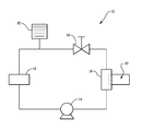
The FIGURE depicts a schematic diagram of an exemplary heat transfer system.
DETAILED DESCRIPTION OF THE INVENTION
Referring now to the FIGURE, an exemplary heat transfer system with a heat transfer fluid circulation loop is shown in block diagram form in the FIGURE. As shown in the FIGURE, heat exchange system 10 includes heat source 12, pump 14, heat exchanger 16, flow control means 18 and fluid reservoir 20. Generally speaking, pump 14 pumps fluid through heat exchange system 10. The flow of fluid through heat exchange system 10 is controlled by pump 14 and flow control means 18. Fluid is added to or removed from heat exchange system 10 via fluid reservoir 20. Heat exchanger 16 is a cooling type heat exchanger for cooling the fluid in heat exchange system 10. Heat exchanger 16 is in fluid communication with coolant loop 22. For the reasons stated above, one or more components of heat exchange system 10 such as pump 14, heat exchanger 16, flow control means 18 or coolant loop 22 contain surfaces having high aluminum and/or nickel surface areas. As a result of the large amounts of aluminum and/or nickel present in components of heat exchange system 10, the component surfaces are subject to corrosion and the aforementioned problems when conventional aqueous-based coolants are used. To cool these component surfaces and prevent unwanted corrosion, heat exchange system 10 contains the aqueous-based coolant described above.
In some embodiments, the heat transfer system includes at least one aluminum surface in contact with the heat transfer fluid. “Aluminum” refers to pure aluminum as well as aluminum alloys (e.g., alloys in which aluminum is the predominant metal). Depending on the temperature and specific function of a component or system that requires heating or cooling, the component or system may contain surfaces with large amounts of aluminum. The benefits of aluminum (high strength-to-weight ratio, durability, malleability) allow for size and/or weight reduction compared to other materials. For example, aluminum microchannel heat exchangers can be used as an alternative to conventional heat exchangers, and can provide beneficial size, weight, and heat transfer efficiency. The smaller volume of the heat exchanger and the lower density of aluminum also contribute to reduce the overall weight of the system, often considered a critical design parameter for aircraft and spacecraft. Microchannel heat exchangers typically provide small clearances between component surfaces and small gaps in coolant flow paths. In some heat exchangers, gaps between fins can be as low as about 0.5 mm (0.020 inches), while cold plates can have gaps as low as about 0.6 mm (0.025 inches). Flow control valves can have gaps as small as about 0.3 mm (0.012 inches), and pumps can have clearances between the bushing and shaft between about 0.025 mm (0.001 inches) and about 0.04 mm (0.0015 inches). These clearances and gaps can be sensitive to coolant precipitates and aluminum corrosion products. Precipitates within the aqueous-based coolant and dislodged corrosion products can block these small gaps to impede, restrict or block coolant flow.
Various components in the heat transfer system can have aluminum surfaces in contact with the heat transfer fluid, including but not limited to cold plates, heat exchangers, and/or heat transfer fluid flow conduits. Heat exchangers can themselves include various sub-components such as manifolds, heat transfer fluid flow tubes or channels, and fins in thermal contact with the heat transfer fluid flow tubes or channels. Any of the above components can be include aluminum surfaces in contact with the heat transfer fluid. The listed components are exemplary, and the system can contain other aluminum components in contact with the heat transfer fluid.
The heat transfer systems described herein can have significant amounts of aluminum surface area. In some embodiments, the ratio of aluminum surface area to coolant volume ratio is greater than or equal to 1.0 cm2 aluminum surface area per mL of coolant, more specifically greater than or equal to 2.0 cm2 aluminum surface area per mL of coolant, and even more specifically greater than or equal to 4.0 cm2 aluminum surface area per mL of coolant. In one exemplary embodiment, the aluminum surface area to coolant volume ratio is about 4.7 cm2 aluminum surface area per mL of coolant (12 square inches per cubic inch) in a flowing system and 34.6 cm2/mL (88 square inches per cubic inch) in a static condition. Such levels of aluminum in the system can create particularly onerous demands on heat transfer fluid performance with respect to corrosion resistance. Due to the high aluminum surface area, some commonly used additives can be omitted from the aqueous-based coolant. For example, materials such as copper and carbon steel are not routinely used in applications such as spacecraft applications, with aluminum often used instead. Therefore, the aqueous-based coolant does not need to contain additives that specifically inhibit corrosion of these materials. The omission of these additives removes their potential unwanted effects from the aqueous-based coolant. For instance, azoles and nitrites can potentially be detrimental to surfaces in some spacecraft applications. Azole/organic acid reaction products can contribute to the fouling of filters used in heat transfer systems. Nitrites can reduce to ammonia and shift the pH of the aqueous-based coolant above its effective range in systems having high aluminum surface area, which can also cause the coolant to react negatively with aluminum surfaces. In exemplary embodiments, the aqueous-based coolant is free of azoles and nitrites.
As described herein, the pH of the solution is maintained in the range of 7.8 to 8.0, more specifically at about 7.9. The target pH can be achieved with a combination of an appropriate amount of base such as potassium hydroxide in combination with a buffer composition. The buffer composition comprises sodium and/or potassium salts of borate, carbonate, and bicarbonate in amounts ranging from 1.00 wt. % to 1.20 wt. % more specifically from 1.09.% to 1.12 wt. %, based on the total weight of the heat transfer fluid. The relative proportion of the components of the buffer composition can be optimized based on solubility in the working range of the desired coolant and corrosion inhibition needs. In more specific embodiments, the buffer comprises sodium borate, sodium carbonate, and sodium bicarbonate. In some embodiments, the heat transfer fluid comprises from 0.10 wt. % to 0.40 wt. % and more specifically from 0.20 wt. % to 0.28 wt. % of sodium borate, from 0.10 wt. % to 0.40 wt. % and more specifically from 0.19 wt. % to 0.27 wt. % of sodium carbonate, and from 0.40 wt. % to 0.80 wt. % and more specifically from 0.58 wt. % to 0.66 wt. % of sodium bicarbonate, based on the total weight of the heat transfer fluid. In some, more specific embodiments, the buffer composition comprises from 0.20 wt. % to 0.28 wt. % of sodium borate, from 0.19 wt. % to 0.27 wt. % of sodium carbonate, and from 0.58 wt. % to 0.66 wt. % of sodium bicarbonate, based on the total weight of the buffer composition.
As described herein, the heat transfer fluid comprises a mixture of organic acids, more specifically from 0.40 wt. % to 0.60 wt. % of a straight chain aliphatic dicarboxylic acid, from 0.90 wt. % to 1.10 wt. % of a branched aliphatic carboxylic acid, and from 0.40 wt. % to 0.60 wt. % of an aromatic carboxylic acid. In more specific embodiments, the heat transfer fluid comprises from 0.45 wt. % to 0.55 wt. % of a straight chain aliphatic dicarboxylic acid, from 0.95 wt. % to 1.05 wt. % of a branched aliphatic carboxylic acid, and from 0.45 wt. % to 0.55 wt. % of an aromatic carboxylic acid. Examples of straight chain aliphatic dicarboxylic acids include C8-C12 dicarboxylic acids such as suberic acid, azeleic acid, sebacic acid, and dodecanedioic acid. In a more specific embodiment, the straight chain dicarboxylic acid is sebacic acid. Examples of branched aliphatic carboxylic acids include C6-C10 monocarboxylic acids having at least one branch therein, such as 2-ethylhexanoic acid, 3-ethyl-6-methylcotanedioic acid, 4-methyl pentanoic acid, and 2,3-dimethylhexanoic acid. Examples of aromatic carboxylic acids include benzoic acid, benzoyl acid, phthaloyl acid, and phthalic acid
The heat transfer fluid also includes from 0.04 wt. % to 0.08 wt. % of a molybdate salt, more specifically from 0.055 wt. % to 0.065 wt. % of a molybdate salt. Molybdate salts contain an oxoanion of molybdenum in its highest oxidation state of 6. Molybdate oxoanions can be provided in solution by alkali metal molybdates, alkali earth molybdates, ammonium molybdate and organic molybdate compounds. An exemplary source of molybdate salt is sodium molybdate. Sodium molybdate is a non-oxidizing anodic inhibitor having the molecular formula Na2MoO4. Sodium molybdate is often found as a dihydrate (Na2MoO4.2H2O).
The heat transfer fluid also includes from 0.01 wt. % to 0.03 wt. % of an aldehyde biocide, more specifically from 0.015 wt. % to 0.025 wt. % of an aldehyde biocide. Virtually any aldehyde capable of being dissolved in the solution can function as a biocide. Specific examples of aldehyde biocides include glutaraldehyde and ortho-phthaldehyde. In a more specific embodiment, the aldehyde biocide is ortho-phthaldehyde.
The heat transfer system described herein can be used, for example, to condition air in an interior space by either transferring heat from the interior space to an outside environment or by transferring heat from an outside environment to the conditioned interior space, and as used herein, the terms “coolant” and “refrigerant” are used interchangeably with the term “heat transfer fluid”, which may be used for either heating or cooling a conditioned space. In some embodiments, the conditioned interior space can be a sealed interior space such as a space vehicle, submarine, or other hermetically sealed environment. In some embodiments, a portion of the heat transfer fluid in the system is in a frozen state.
The invention is further illustrated by the following non-limiting example.
EXAMPLE 1 Stability Testing
Into a 2-liter volumetric flask containing about 1.75 liters of deionized water, the following ingredients were added with stirring until dissolution: 4.88 g Na2B4O7.10 H2O (1000-ppm B4O7 2−), 4.94 g Na2CO3 (1400-ppm CO3 2−), and 12.1 g NaHCO3 (4400-ppm HCO3 ). 400 mg of ortho-phthalaldehyde were added to the flask followed by additional deionized water to yield 2 liters of solution. 1 liter of the above solution was added to a 2-liter beaker with a magnetic stiffing bar, to which was added 11.0-mL 2-ethylhexanoic acid (1.0% w/w), 5.0 g benzoic acid (0.5% w/w), 5.0 g sebacic acid (0.5% w/w), and 600 mg sodium molybdate (0.06% w/w). The mixture was stirred for 24 hours to completely dissolve the ingredients. The pH of the solution was adjusted to 7.9 by adding potassium hydroxide flakes until a pH ≧7, and then adding 1.0 N and then 0.1N potassium hydroxide solution drop-wise to reach the final pH of 7.9.
A 1500 ml volume of the above solution was tested for stability over a 60-day period by initially increasing the temperature to 60° C. for 24 hours followed by 24 hours at room temperature. Thereafter, the solution was subjected to a temperature of 1.7° C. for 24 hours and then returned to room temperature for the balance of the 60-day period. The solution remained clear through the test protocol with no signs of precipitation or stratification. Thirteen days into the test, a 300 ml aliquot of the solution was separated from the main sample and frozen at −20° C. for 24 hours. This solution was returned to room temperature and maintained at room temperature for the remaining 47 days of the 60-day period, with no observable precipitation or stratification.
EXAMPLE 2 Corrosion Testing
The above solution was tested for corrosion by abrading 1 cm2 test samples of aluminum alloy 6951 with 400 grit sand paper followed by cleaning in Vertrel MCA®. The test samples were soaked in the solution for about 2.5 weeks, followed by cyclic potentiodynamic polarization testing according to ASTM G5 using Teflon crevice-free washers. Data was collected and plotted as the log of corrosion current in amperes per cm2 as a function of polarization potential in volts vs. a saturated calomel electrode. Data manipulation was performed using Tafel extrapolation according to ASTM G102, using equivalent weight of 6951 Aluminum Alloy of 9.032, the density is 2.7 g/cm3, and a Stern Greary coefficient of 26 mV for Tafel Extrapolation. This gave corrosion rates of 0.229 MPY (milli-inches per year) for a first trial and 0.255 MPY for a second trial. For comparison purposes, corrosion of aluminum alloy 6951 in water at a pH of 7.9 but without the composition of the invention has been reported at a substantially higher 3.9 MPY.
While the invention has been described in detail in connection with only a limited number of embodiments, it should be readily understood that the invention is not limited to such disclosed embodiments. Rather, the invention can be modified to incorporate any number of variations, alterations, substitutions or equivalent arrangements not heretofore described, but which are commensurate with the spirit and scope of the invention. Additionally, while various embodiments of the invention have been described, it is to be understood that aspects of the invention may include only some of the described embodiments. Accordingly, the invention is not to be seen as limited by the foregoing description, but is only limited by the scope of the appended claims.

Claims (20)

The invention claimed is:
1. A heat transfer system comprising a heat exchanger disposed in a heat transfer fluid circulation loop, wherein the heat transfer fluid is an aqueous solution having a pH of 7.8 to 8.0 that comprises:
1.00 wt. % to 1.20 wt. % of a buffer composition comprising sodium and/or potassium salts of borate, carbonate, and bicarbonate;
0.40 wt. % to 0.60 wt. % of a straight chain aliphatic dicarboxylic acid;
0.90 wt. % to 1.10 wt. % of a branched aliphatic carboxylic acid;
0.40 wt. % to 0.60 wt. % of an aromatic carboxylic acid;
0.04 wt. % to 0.08 wt. % of a molybdate salt; and
0.01 wt. % to 0.03 wt. % of an aldehyde biocide;
each weight percentage based on the total weight of the heat transfer fluid.
2. The heat transfer system of claim 1, wherein the heat transfer system includes a surface comprising aluminum in contact with the heat transfer fluid.
3. The heat transfer system of claim 2, wherein the surface comprising aluminum is a component of a heat exchanger, a cold plate, or a fluid conduit.
4. The heat transfer system of claim 2, comprising a plurality of heat exchangers including a surface comprising aluminum in contact with the heat transfer fluid.
5. The heat transfer system of claim 2, having a ratio of aluminum surface are to heat transfer fluid volume of at least 1.0 cm2/ml.
6. The heat transfer system of claim 1, wherein the buffer composition comprises sodium borate, sodium carbonate, and sodium bicarbonate.
7. The heat transfer system of claim 5, wherein the buffer composition comprises from 0.10 wt. % to 0.40 wt. % of sodium borate, from 0.10 wt. % to 0.40 wt. % of sodium carbonate, and from 0.40 wt. % to 0.80 wt. % of sodium bicarbonate, based on the total weight of the heat transfer fluid.
8. The heat transfer system of claim 1, wherein the straight chain aliphatic dicarboxylic acid is a C8-C12 dicarboxylic acid, the branched aliphatic carboxylic acid is a C4-C12 monocarboxylic acid having at least one branch therein, and the aromatic carboxylic acid is benzoic acid.
9. The heat transfer system of claim 7, wherein the straight chain aliphatic dicarboxylic acid is sebacic acid and the branched aliphatic carboxylic acid is 2-ethylhexanoic acid.
10. The heat transfer system of claim 1, wherein the aldehyde biocide is ortho-phthaldehyde or glutaraldehyde.
11. The heat transfer system of claim 9, wherein the aldehyde is orthophthaldehyde.
12. The heat transfer system of claim 1, wherein the molybdate salt is sodium molybdate.
13. The heat transfer system of claim 1, wherein the heat transfer fluid comprises from 1.09 wt. % to 1.12 wt. % of the buffer composition, from 0.45 wt. % to 0.55 wt. % of the straight chain aliphatic dicarboxylic acid, from 0.95 wt. % to 1.05 wt. % of the branched aliphatic carboxylic acid, from 0.45 wt. % to 1.05 wt. % of benzoic acid as the aromatic carboxylic acid, from 0.055 wt. % to 0.065 wt. % of the molybdate salt, and from 0.015 wt. % to 0.025 wt. % of the aldehyde biocide, based on the total weight of the heat transfer fluid.
14. The heat transfer system of claim 1, wherein the buffer composition comprises sodium borate, sodium carbonate, and sodium bicarbonate, the straight chain aliphatic dicarboxylic acid is sebacic acid, the branched aliphatic carboxylic acid is 2-ethylhexanoic acid, the aromatic carboxylic acid is benzoic acid, the molybdate salt is sodium molybdate, and the aldehyde biocide is ortho-phthaldehyde.
15. A method of operating a heat transfer system comprising circulating a heat transfer fluid through a heat exchanger disposed in a heat transfer fluid circulation loop, wherein the heat transfer fluid is an aqueous solution having a pH of 7.8 to 8.0 that comprises:
1.00 wt. % to 1.20 wt. % of a buffer composition comprising sodium and/or potassium salts of borate, carbonate, and bicarbonate;
0.40 wt. % to 0.60 wt. % of a straight chain aliphatic dicarboxylic acid;
0.90 wt. % to 1.10 wt. % of a branched aliphatic carboxylic acid;
0.40 wt. % to 0.60 wt. % of an aromatic carboxylic acid;
0.04 wt. % to 0.08 wt. % of a molybdate salt; and
0.01 wt. % to 0.03 wt. % of an aldehyde biocide;
each weight percentage based on the total weight of the heat transfer fluid.
16. The method of claim 15, wherein the heat transfer system includes a surface comprising aluminum in contact with the heat transfer fluid.
17. The method of claim 16, having a ratio of aluminum surface area to heat transfer fluid volume of at least 1.0 cm2/ml.
18. The method of claim 15, wherein a portion of the heat transfer fluid is in a frozen state.
19. A heat transfer fluid, comprising, in an aqueous solution having a pH of 7.8 to 8.0:
1.00 wt. % to 1.20 wt. % of a buffer composition comprising sodium and/or potassium salts of borate, carbonate, and bicarbonate;
0.40 wt. % to 0.60 wt. % of a straight chain aliphatic dicarboxylic acid;
0.90 wt. % to 1.10 wt. % of a branched aliphatic carboxylic acid;
0.40 wt. % to 0.60 wt. % of an aromatic carboxylic acid;
0.04 wt. % to 0.08 wt. % of a molybdate salt; and
0.01 wt. % to 0.03 wt. % of an aldehyde biocide;
each weight percentage based on the total weight of the heat transfer fluid.
20. The heat transfer fluid of claim 19, wherein the buffer composition comprises sodium borate, sodium carbonate, and sodium bicarbonate, the straight chain aliphatic dicarboxylic acid is sebacic acid, the branched aliphatic carboxylic acid is 2-ethylhexanoic acid, the aromatic carboxylic acid is benzoic acid, the molybdate salt is sodium molybdate, and the aldehyde biocide is ortho-phthaldehyde.
US13/855,378 2013-04-02 2013-04-02 Heat transfer system with aqueous heat transfer fluid Active 2034-08-19 US9260644B2 (en)

Priority Applications (1)

Application Number Priority Date Filing Date Title
US13/855,378 US9260644B2 (en) 2013-04-02 2013-04-02 Heat transfer system with aqueous heat transfer fluid

Applications Claiming Priority (1)

Application Number Priority Date Filing Date Title
US13/855,378 US9260644B2 (en) 2013-04-02 2013-04-02 Heat transfer system with aqueous heat transfer fluid

Publications (2)

Publication Number Publication Date
US20140290912A1 US20140290912A1 (en) 2014-10-02
US9260644B2 true US9260644B2 (en) 2016-02-16

Family

ID=51619669

Family Applications (1)

Application Number Title Priority Date Filing Date
US13/855,378 Active 2034-08-19 US9260644B2 (en) 2013-04-02 2013-04-02 Heat transfer system with aqueous heat transfer fluid

Country Status (1)

Country Link
US (1) US9260644B2 (en)

Citations (2)

* Cited by examiner, † Cited by third party
Publication number Priority date Publication date Assignee Title
US5997763A (en) * 1998-04-27 1999-12-07 Shell Oil Company Corrosion inhibiting antifreeze compositions containing various carboxylic acids
US20120111536A1 (en) 2010-11-10 2012-05-10 Hamilton Sundstrand Corporation Aqueous based cooling of components having high surface area levels of aluminum or nickel

Patent Citations (2)

* Cited by examiner, † Cited by third party
Publication number Priority date Publication date Assignee Title
US5997763A (en) * 1998-04-27 1999-12-07 Shell Oil Company Corrosion inhibiting antifreeze compositions containing various carboxylic acids
US20120111536A1 (en) 2010-11-10 2012-05-10 Hamilton Sundstrand Corporation Aqueous based cooling of components having high surface area levels of aluminum or nickel

Also Published As

Publication number Publication date
US20140290912A1 (en) 2014-10-02

Similar Documents

Publication Publication Date Title
KR101618285B1 (en) Heat transfer fluids and corrosion inhibitor formulations for use thereof
CZ20011220A3 (en) Corrosion inhibitors and synergistic combinations of inhibitors for protection of light metals in heat-transferring liquids and motor coolants
US20060237685A1 (en) Coolant composition and methods of use thereof
JP2012526180A (en) Antifreeze concentrates and coolant compositions and their manufacture
AU2019204001B2 (en) Extended operation engine coolant composition
CN108138033A (en) Heat transfer fluid composition and purposes
JP2006052404A (en) Silicate-free cooling liquid having improved corrosiveness based on organic acid and carbamate
US20050218370A1 (en) Heat transfer medium liquid composition
EP2452995B1 (en) Aqueous based cooling of components having high surface area levels of aluminum or nickel
CZ20014588A3 (en) Corrosion-inhibiting composition for heat-carrying liquids
US9260644B2 (en) Heat transfer system with aqueous heat transfer fluid
MXPA01008616A (en) Monocarboxylic acid based antifreeze composition for diesel engines.
US20070194270A1 (en) Buffered heat transfer fluid for secondary refrigeration systems comprising a formate salt
US9540558B2 (en) Extended operation engine coolant composition
JP2002371270A (en) Antifreeze
JP4474142B2 (en) Coolant for internal combustion engine and method for regenerating the same
JP2001158878A (en) Cooling liquid composition
CN103160246A (en) Water-based cooling for component with high aluminium surface area level or high nickel surface area level
JP6973057B2 (en) Heat transport medium and heat transport system
JP2002030281A (en) Cooling liquid composition
JP2004292513A (en) Liquid coolant and cooling system using the sane
JP2005113250A (en) Cooling liquid composition
JP2009256735A (en) Cooling liquid composition
JP2006137996A (en) Liquid coolant composition
BR112015031002B1 (en) ENGINE COOLANT COMPOSITION, METHOD TO REDUCE CORROSION LOCATED IN AN ENGINE, AND METHOD TO INHIBIT CORROSION IN AN IRON-CONTENT COMPONENT OF AN ENGINE COOLING SYSTEM

Legal Events

Date Code Title Description
AS Assignment

Owner name: HAMILTON SUNDSTRAND SPACE SYSTEMS INTERNATIONAL, I

Free format text: ASSIGNMENT OF ASSIGNORS INTEREST;ASSIGNORS:STEELE, JOHN W.;MONTEFUSCO, DANIEL;PEYTON, BARBARA M.;AND OTHERS;SIGNING DATES FROM 20130327 TO 20130402;REEL/FRAME:030134/0801

STCF Information on status: patent grant

Free format text: PATENTED CASE

MAFP Maintenance fee payment

Free format text: PAYMENT OF MAINTENANCE FEE, 4TH YEAR, LARGE ENTITY (ORIGINAL EVENT CODE: M1551); ENTITY STATUS OF PATENT OWNER: LARGE ENTITY

Year of fee payment: 4

MAFP Maintenance fee payment

Free format text: PAYMENT OF MAINTENANCE FEE, 8TH YEAR, LARGE ENTITY (ORIGINAL EVENT CODE: M1552); ENTITY STATUS OF PATENT OWNER: LARGE ENTITY

Year of fee payment: 8