US9258546B2 - Three-dimensional imaging system and image reproducing method thereof - Google Patents
Three-dimensional imaging system and image reproducing method thereof Download PDFInfo
- Publication number
- US9258546B2 US9258546B2 US13/762,926 US201313762926A US9258546B2 US 9258546 B2 US9258546 B2 US 9258546B2 US 201313762926 A US201313762926 A US 201313762926A US 9258546 B2 US9258546 B2 US 9258546B2
- Authority
- US
- United States
- Prior art keywords
- user
- image
- cameras
- camera
- images
- Prior art date
- Legal status (The legal status is an assumption and is not a legal conclusion. Google has not performed a legal analysis and makes no representation as to the accuracy of the status listed.)
- Active, expires
Links
Images


Classifications
-
- H—ELECTRICITY
- H04—ELECTRIC COMMUNICATION TECHNIQUE
- H04N—PICTORIAL COMMUNICATION, e.g. TELEVISION
- H04N13/00—Stereoscopic video systems; Multi-view video systems; Details thereof
- H04N13/20—Image signal generators
- H04N13/204—Image signal generators using stereoscopic image cameras
- H04N13/239—Image signal generators using stereoscopic image cameras using two 2D image sensors having a relative position equal to or related to the interocular distance
-
- H04N13/0239—
-
- H04N13/0025—
-
- H04N13/0246—
-
- H04N13/0296—
-
- H—ELECTRICITY
- H04—ELECTRIC COMMUNICATION TECHNIQUE
- H04N—PICTORIAL COMMUNICATION, e.g. TELEVISION
- H04N13/00—Stereoscopic video systems; Multi-view video systems; Details thereof
- H04N13/10—Processing, recording or transmission of stereoscopic or multi-view image signals
- H04N13/106—Processing image signals
- H04N13/133—Equalising the characteristics of different image components, e.g. their average brightness or colour balance
-
- H—ELECTRICITY
- H04—ELECTRIC COMMUNICATION TECHNIQUE
- H04N—PICTORIAL COMMUNICATION, e.g. TELEVISION
- H04N13/00—Stereoscopic video systems; Multi-view video systems; Details thereof
- H04N13/20—Image signal generators
- H04N13/204—Image signal generators using stereoscopic image cameras
- H04N13/246—Calibration of cameras
-
- H—ELECTRICITY
- H04—ELECTRIC COMMUNICATION TECHNIQUE
- H04N—PICTORIAL COMMUNICATION, e.g. TELEVISION
- H04N13/00—Stereoscopic video systems; Multi-view video systems; Details thereof
- H04N13/20—Image signal generators
- H04N13/296—Synchronisation thereof; Control thereof
Definitions
- Example embodiments of the following disclosure relate to a three-dimensional (3D) imaging system for displaying a 3D image suitable for a user, and an image reproducing method thereof.
- the 3D stereoscopic image that represents a 3D figure depends on the stereo vision theory through two eyes that enables a 3D sense of an object to be perceived by use of the disparity of two eyes, that is, the binocular disparity caused by the distance of about 65 mm between two eyes. That is, when each of the left eye and the right eye of a user views a respective 2D image that is related to each eye, the images of the two eyes are transmitted to the brain through a retina, and the brain fuses the two images, thereby reproducing the depth perception and the sense of reality.
- a left side 3D image viewed from the left eye and a right side 2D image viewed from the right eye are obtained from a stereo camera, and a signal processing is performed on each image, thereby displaying a 3D stereoscopic image.
- the stereo camera uses two camera modules each having camera parameters (e.g., the size of the screen, the focus, the brightness, the sense of color, and field of view (FOV)) that are almost same in between the two camera modules in terms of hardware (H/W).
- camera parameters e.g., the size of the screen, the focus, the brightness, the sense of color, and field of view (FOV)
- H/W hardware
- the stereo camera manufactured as above is costly and is provided with a lowered freedom of operation, and in particular, has a narrow section of the cameras.
- a 3D imaging system includes a user input unit, a stereo camera, a control unit and a driving apparatus.
- the user input unit may be configured to input user information.
- the stereo camera may be configured to obtain a 2D image.
- the control unit may be configured to control a pose of the stereo camera according to the user information such that a 3D image suitable for a user is reproduced from the 2D image obtained through the stereo camera.
- the driving apparatus may be configured to move the stereo camera according to a control of the control unit.
- the user information may include information about a disposition of eyes of the user and an eyesight of the user.
- the stereo camera may include two cameras each configured to obtain a 2D image.
- the two cameras may represent a left side camera and a right side camera each having a different parameter.
- the driving apparatus may represent a plurality of motors driven to adjust poses of the left side camera and the right side camera.
- the plurality of motors may include a plurality of left side motors configured to move the left side camera in X and Y directions, and a plurality of right side motors configured to move the right side camera in X and Y directions.
- the 3D imaging system may further include a user DB configured to store information about a pose of the stereo camera, which is adjusted according to the user information, in a form of a database.
- the stereo camera may include a left side camera and a right side camera each having a different parameter.
- the control unit may update the user DB according to the parameters of the two cameras.
- the 3D imaging system may further include an image processing unit and an image generating unit.
- the image processing unit may be configured to reconstruct a left side image and a right side image by combining images obtained from the two cameras with the information about the pose of the stereo camera.
- the image generating unit may be configured to generate the 3D image suitable for the user from the reconstructed left and right side images.
- the 3D imaging system may further include an image processing unit and an image generating unit.
- the image processing unit may be configured to reduce a disparity of images obtained from the two cameras by use of the user DB.
- the image generating unit may be configured to generate the 3D image suitable for the user from the images, which have the disparity thereof reduced, obtained by the two cameras.
- the image processing unit may extract regions that overlap between the images obtained by the two cameras, calculate each brightness of the extracted regions to obtain an average of the brightness, and change a brightness of each pixel according to the average, thereby reducing the disparity of the images obtained from the two cameras.
- the image processing unit may extract regions that overlap between the images obtained by the two cameras, and adjust a sampling time according to a size of the extracted region, thereby reducing the disparity of the images obtained from the two cameras.
- a method of reproducing a 3D image based on a stereo camera is as follows.
- a 2DI image may be obtained through the stereo camera.
- the 2D image may be adjusted to be suitable for a user by moving the stereo camera.
- Information about a pose of the stereo camera that is adjusted to be suitable for the user may be stored in a user DB.
- a 3D image suitable for the user may be output by controlling a pose of the stereo camera according to the information about the pose of the stereo stored in the user DB.
- the adjusting of the 2D image to be suitable for the user may be achieved by adjusting the pose of the stereo camera to be suitable for a disposition of eyes of the user and an eyesight of the user.
- the stereo camera may include two cameras each having a different parameter.
- a left side image and a right side image may be reconstructed by combining images obtained from the two cameras with the information about the pose of the stereo camera stored in the user DB.
- the 3D image suitable for the user may be generated from the reconstructed left and right side images.
- the method may be achieved by further performing as follows. Regions that overlap between the images obtained by the two cameras may be extracted. Brightness of each of the extracted regions may be calculated to obtain an average of the brightness. Brightness of each pixel may be changed according to the average, thereby reducing a disparity of the images obtained from the two cameras.
- the method may be achieved by further performing as follows. Regions that overlap between the images obtained by the two cameras may be extracted. A sampling time may be adjusted according to a size of the extracted region, thereby reducing a disparity of the images obtained from the two cameras.
- a method of reproducing a 3D image including: adjusting a placement of a stereo camera according to a disposition of eyes of a user; obtaining at least two 2D images from the stereo camera; and generating the 3D image, based on the obtained 2D images.
- the stereo camera system is configured to have different cameras, different cameras may be freely selected without restriction.
- the stereo camera system is configured to enable the placement of the cameras thereof to be changeable, a 3D image is generated and displayed from a stereo image adapted to the user by changing the placement of the cameras according to the disposition of eyes of the user.
- various contents services including a real time broadcasting, a Contents on Demand (COD), games, and a video communication are provided to a user, so that the fatigue or dizziness of a user is reduced, and the optimum perception of 3D sense is provided.
- COD Contents on Demand
- FIG. 1 is a block diagram illustrating the configuration of a three-dimensional (3D) imaging system based on a stereoscopy in accordance with an example embodiment of the present disclosure.
- FIG. 2 illustrates the schematic configuration of a driving apparatus configured to move a stereo camera in accordance with an example embodiment of the present disclosure.
- FIGS. 3A and 3B are flow charts illustrating the operation of generating a user database (DB) at the 3D imaging system in accordance with an example embodiment of the present disclosure.
- DB user database
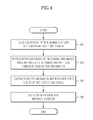
- FIG. 4 is a flow chart illustrating the operation of performing a camera calibration at the 3D imaging system in accordance with an example embodiment of the present disclosure.
- FIG. 5 is a view illustrating a calibration pattern for the camera calibration of FIG. 4 .
- FIG. 6 is a view illustrating the calibration pattern of FIG. 5 placed in the middle of the stereo camera.
- FIG. 7 is a flow chart illustrating a method of outputting a 3D image by controlling the pose of a camera according to the user information at the 3D imaging system in accordance with an example embodiment of the present disclosure.
- FIG. 8 is a flow chart illustrating a first method of reducing the disparity of images generated due to the asynchronous operation between two cameras at the 3D imaging system in accordance with an example embodiment of the present disclosure.
- FIG. 9 is a flow chart illustrating a second method of reducing the disparity of images generated due to the asynchronous operation between two cameras at the 3D imaging system in accordance with an example embodiment of the present disclosure.
- FIG. 1 is a view illustrating the configuration of a three-dimensional (3D) imaging system based on a stereoscopy in accordance with an example embodiment of the present disclosure.
- a 3D imaging system in accordance with an example aspect of the present disclosure includes a stereo camera 10 , an image extracting unit 20 , a driving apparatus 30 , a motion control unit 40 , a user input unit 50 , a user database (DB) 60 , a camera pose control unit 70 , an image processing unit 80 , an image generating unit 90 , and an image display unit 100 .
- DB user database
- the stereo camera 10 obtains two-dimensional (2D) images from two cameras 10 L and 10 R, respectively, and transmits the obtained 2D images to the image extracting unit 20 .
- Reference numerals L and R denote the left side and the right side of the stereo camera 10 , respectively.
- Each of the two cameras 10 L and 10 R has a different parameter, for example, the size of a screen, the focus, the brightness, the sense of color, and field of view (FOV), from each other.
- a different parameter for example, the size of a screen, the focus, the brightness, the sense of color, and field of view (FOV), from each other.
- the image extracting unit 20 may represent an image capture module configured to extract an image that has been obtained from the stereo camera 10 ( 10 L and 10 R), and includes a left side image extracting unit 21 to extract a left side image obtained from the left side camera 10 L and a right side image extracting unit 22 to extract a right side image obtained from the right side camera 10 R.
- the left side image extracted by the left side extracting unit 21 and the right side image extracted by the right side extracting unit 22 are transmitted to the image processing unit 80 .
- the driving apparatus 30 is a motor driven to change the pose, for example, the direction and the position, of the stereo camera 10 ( 10 L and 10 R), and includes left side motors 31 and 32 to move the left side camera 10 L in X and Y directions, and right side motors 33 and 34 to move the right side camera 10 R in X and Y directions.
- the motion control unit 40 is a motion control module configured to control the driving apparatus 30 to change the pose, for example, direction and position, of the stereo camera 10 ( 10 L and 10 R), and is configured to control the motion of the left side motors 31 and 32 and the right side motors 33 and 34 to move the two cameras 10 L and 10 R in X and Y directions.
- the user input unit 50 is an apparatus configured to input user information about the disposition and characteristics of eyes of a user, for example, the eyesight of eyes.
- the user DB 60 may be a database that stores the information about the pose, for example, direction and position, of the camera with respect to the disposition and characteristic of the eyes of the user.
- the camera pose control unit 70 is a controller configured to control the pose, for example, direction and position, of the cameras 10 L and 10 R according to the user information, and is configured to control the pose of the cameras 10 L and 10 R according to the user information such that two images obtained from the stereo camera 10 ( 10 L and 10 R) are suitable for reproducing a 3D image.
- the camera pose control unit 70 may update the user DB 60 by searching for the parameters, for example, the size of the screen, the focus, the sense of color and FOV, that are different in the stereo camera 10 ( 10 L and 10 R).
- the image processing unit 80 may represent an image matching module configured to reduce the disparity between images obtained from the two cameras 10 L and 10 L of the stereo camera 10 . Further, the image processing unit 80 may be configured to reduce the disparity between images, which is generated due to the asynchronous operation between the two cameras 10 L and 10 R, by use of the camera parameters obtained from the camera pose control unit 70 and the user information inputted using the user input unit 50 .
- the image processing unit 80 may transmit the stereo images having the reduced disparity, which is generated due to the asynchronous operation between the two cameras 10 L and 10 R, to the image generating unit 90 . As such, the sense of stereoscopic effect is increased in a process of generating the 3D image from the 2D image.
- the image generating unit 80 may a stereoscopic image generator configured to generate a 3D image from the stereo images that have been processed by the image processing unit 80 .
- the stereoscopic technique for generating a 3D image uses a theory in which 2D images, which are obtained from the two cameras 10 L and 10 R spaced apart from each other by a distance between two eyes of a human, are alternately viewed at a significantly small period of time, and a brain of the human mistakenly recognizes the 2D images as a 3D image.
- the image display unit 100 is a 3D display device configured to reproduce a 3D image generated from the image generating unit 90 , and includes a 3D television, and a head mounted display (HMD).
- HMD head mounted display
- FIG. 2 is a view illustrating the schematic configuration of a driving apparatus configured to move a stereo camera in accordance with an example embodiment of the present disclosure.
- the driving apparatus 30 may include the left side motors 31 and 32 and the right side motors 33 and 34 that are driven to change the pose (direction and position in an X and Y direction) of the stereo camera 10 ( 10 L and 10 R).
- the left side motors 31 and 32 may include an X-axis left side motor 31 to move the left side camera 10 L in the X direction and a Y-axis left side motor 32 to move the left side camera 10 L in the Y direction.
- the right side motors 33 and 34 include an X-axis right side motor 33 to move the right side camera 10 R in the X direction and a Y-axis right side motor 34 to move the right side camera 10 R in the Y direction.
- the number of the left side motors 31 and 32 and the right side motors 33 and 34 may vary depending on the desired pose of the cameras 10 L and 10 R for change. For example, in order to change six degrees of freedom, at least six motor is needed, and thus, the present disclosure is not limited to using four motors.
- FIGS. 3A and 3B are flow charts illustrating the operation of generating a user DB at the 3D imaging system in accordance with an example embodiment of the present disclosure.
- the camera pose control unit 70 may select one of the left side camera 10 L and the right side camera 10 R, and move the selected camera.
- the camera pose control unit 70 selecting and moving the left side camera 10 L ( 200 ). Again, the present disclosure is not limited thereto, and thus, the camera pose control unit 70 may also select and move the right side camera 10 R.
- the left side camera 10 L photographs 2D images at each position to which the left side camera 10 L is moved by the camera pose control unit 70 , that is, photographs images obtained by the left side camera 10 L ( 202 ).
- a method of photographing 2D images while changing the direction of the left side camera 10 L is as follows.
- the X-axis left side motor 31 is driven by the motion control unit 40 by the control of the camera pose control unit 70 . According to the driving of the X-axis left side motor 31 , the left side camera 10 L changes the direction thereof while moving in the X-axis direction.
- Two dimensional images, which are photographed at a position of the left side eye (hereinafter, referred to as a left eye), among the 2D images photographed by the left side camera 10 L as the above are fixed to a left side image channel, while 2D images, which are photographed at a position of the right side eye (hereinafter, referred to as a right eye) among the 2D images photographed by the left side camera 10 L as the above are output to the image display unit 100 while changing the position.
- the left side camera 10 L performs the photographing while maintaining the height thereof.
- the image display unit 100 may output the same image as the 2D image photographed at the position of the left eye.
- the left side camera 10 L outputs the 2D images, which are photographed while slightly moving from the original position to the right side, to the image display unit 100 , and at the same time measures a point of time (d_inc_left) at which two scenes start to be viewed by a user ( 204 ).
- the motion control unit 40 slightly moves the left side camera 10 L to the left side by driving the X-axis left side motor 31 .
- a point of time (d_dec_left) at which the scenes start to be viewed as a single scene to the user is measured ( 206 ).
- the camera pose control unit 70 photographs 2D images at each position while (212).
- a method of photographing 2D images while changing the height of the left side camera 10 L is as follows.
- the Y-axis left side motor 32 is driven by the motion control unit 40 by the control of the camera pose control unit 70 . According to the driving of the Y-axis left side motor 32 , the left side camera 10 L changes the height thereof while moving in the Y-axis direction.
- the image display unit 100 outputs the same image as the 2D image photographed at the position of the left eye.
- the left side camera 10 L outputs the 2D images, which are photographed while slightly moving from the original position to the upper side, to the image display unit 100 , and at the same time, measures a point of time (h_inc_left) at which two scenes start to be viewed by a user ( 214 ).
- the motion control unit 40 slightly moves the left side camera 10 L to the lower side by driving the Y-axis left side motor 32 .
- a point of time (h_dec_left) at which the scenes start to be viewed as a single scene to the user is measured ( 216 ).
- the camera pose control unit 70 stores the camera pose information (d_user_left) and the camera pose information (h_user_left), that is, the information, that is, direction and position, about the pose of the left side camera 10 L in the user DB 60 ( 220 ).
- the right side camera 10 L photographs 2D images at each position that is moved by the camera pose control unit 70 , that is, images obtained by the right side camera 10 R ( 224 ).
- a method of photographing 2D images while changing the direction of the right side camera 10 R is as follows.
- the X-axis right side motor 33 is driven by the motion control unit 40 by the control of the camera pose control unit 70 . According to the driving of the X-axis right side motor 33 , the right side camera 10 R changes the direction thereof while moving in the X-axis direction.
- Two dimensional images, which are photographed at a position of the left side eye, among the 2D images photographed by the right side camera 10 R as the above are fixed to a left side image channel, while 2D images, which are photographed at a position of the right side eye, among the 2D images photographed by the right side camera 10 R as the above are output to the image display unit 100 while changing the position.
- the right side camera 10 R photographs the 2D images while maintaining the height thereof.
- the image display unit 100 outputs the same image as the 2D image photographed at the position of the left eye.
- the right side camera 10 R outputs the 2D images, which are photographed while slightly moving from the original position to the right side, to the image display unit 100 , and at the same time, measures a point of time (d_inc_right) at which two scenes start to be viewed by a user ( 226 ).
- the motion control unit 40 slightly moves the right side camera 10 R to the left side by driving the X-axis right side motor 33 .
- a point of time (d_dec_right) at which the scenes start to be viewed as a single scene to the user is measured ( 228 ).
- the camera pose control unit 70 photographs 2D images at each position ( 234 ).
- a method of photographing 2D images while changing the height of the right side camera 10 R is as follows.
- the Y-axis right side motor 34 is driven by the motion control unit 40 by the control of the camera pose control unit 70 . According to the driving of the Y-axis right side motor 34 , the right side camera 10 R changes the height thereof while moving in the Y-axis direction.
- the image display unit 100 outputs the same image as the 2D image photographed at the position of the left eye.
- the right side camera 10 R outputs the 2D images, which are photographed while slightly moving from the original position to the upper side, to the image display unit 100 , and at the same time, measures a point of time (h_inc_right) at which two scenes start to be viewed by a user ( 236 ).
- the motion control unit 40 slightly moves the right side camera 10 R to the lower side by driving the Y-axis right side motor 34 .
- a point of time (h_dec_right) at which the scenes start to be viewed as a single scene to the user is measured ( 238 ).
- the camera pose control unit 70 stores the camera pose information (d_user_right) and the camera pose information (h_user_right), that is, the information, for example, direction and position, about the pose of the right side camera 10 R in the user DB 60 ( 242 ).
- FIG. 4 is a flow chart illustrating the operation of performing a camera calibration at the 3D imaging system in accordance with an example embodiment of the present disclosure.
- FIG. 5 is a view illustrating a calibration pattern for the camera calibration of FIG. 4 .
- FIG. 6 is a view illustrating the calibration pattern of FIG. 5 placed in the middle of the stereo camera.
- a calibration pattern 110 shown on FIG. 5 is placed in the middle of the left side camera 10 L and the right side camera 10 R ( 300 ).
- the left side camera 10 L and the right side camera 10 R photograph four sheets of the 2D images while moving by the camera pose information (d_user_left, h_user_left) and the camera pose information (d_user_right, h_user_right) that are stored in the user DB 60 , respectively ( 302 ).
- the total of four images includes (a) a 2D image photographed at the original position of the right side camera 10 R, (b) a 2D image photographed by the right side camera 10 R at the position of the left side camera 10 L, (c) a 2D image photographed at the original position of the left side camera 10 L, and (d) a 2D image photographed by the left side camera 10 L at the position of the right side camera 10 R.
- the camera pose control unit 70 obtains six of fundamental matrices from the four sheets of the 2D images ( 304 ), and stores the obtained six of fundamental matrices in the user DB 60 ( 306 ).
- the six of fundamental matrices includes M1:( a )-( b ), M2:( a )-( c ), M3:( a )-( d ), M4:( b )-( c ), M5:( b )-( d ), and M6: ( c )-( d ).
- FIG. 7 is a flow chart illustrating a method of outputting a 3D image by controlling the pose of a camera according to the user information at the 3D imaging system in accordance with an example embodiment of the present disclosure.
- a user inputs user information through the user input unit 50 ( 400 ).
- the user information is to consider the disposition and the eyesight of human that vary with each person.
- the camera pose control unit 70 obtains a camera pose calibration value depending on the user, for example, the camera pose information (d_user_left, h_user_left) and the camera pose information (d_user_right, h_user_right) from the user DB 60 ( 402 ).
- the camera pose control unit 70 places the camera pose according to the camera pose calibration value obtained from the user DB 60 ( 404 ).
- the image generating unit 90 generates a reconstructed right side camera image (I_new_right) as shown the following equation 2, the reconstructed right side camera image (I_new_right) obtained by combining an image (I_right) input from the right side camera 10 R with an image that is converted from an image (I_left) input by the left side camera 10 L through the fundamental matrix M6 obtained from the user DB 60 .
- I _new_right w*I _right+(1 ⁇ w )* I _left* M 6( w is a value between O and 1) [Equation 2]
- the image generating unit 70 generates a 3D stereoscopic image from the reconstructed left side and right side camera images (I_new_left) and (I_new_right), and outputs the generated 3D stereoscopic image to the image display unit 100 ( 408 ).
- the 3D image is output by controlling the pose of the cameras 10 L and 10 R according to the disposition of the eyes of the user and, so that the 3D stereoscopic image suitable for the user is displayed, thereby reducing the fatigue and dizziness of eyes, and thus, proving the optimum sense of 3D perception.
- the 3D imaging system in accordance with an example embodiment of the present disclosure uses the two cameras 10 L and 10 R each having a different parameter in order to widen the selection of cameras and to implement a cost effective stereo camera, a constraint may occur as a result of the asynchronous operation of the different two cameras 10 L and 10 R.
- the 3D imaging system in accordance with an example embodiment of the present disclosure suggests a method of reducing the disparity between images by performing an image processing on images that are obtained from the different cameras 10 L and 10 R in an asynchronous scheme. The method will be described with reference to FIGS. 8 and 9 .
- FIG. 8 is a flow chart illustrating an example method of reducing the disparity of images generated due to the asynchronous operation between two cameras at the 3D imaging system in accordance with an example embodiment of the present disclosure.
- the two cameras 10 L and 10 R individually supports an auto-white balancing, even if the two cameras 10 L and 10 R are the same camera module having the same camera parameter, the images obtained from the two cameras 10 L and 10 R produce a disparity. Accordingly, the brightness, for example, may need to be matched between the images.
- the image processing unit 80 extracts regions, at which the two camera images overlap, from the two camera images ( 500 ). In this case, if the region is smaller than a threshold area, the matching of brightness is not performed.
- the image processing unit 80 calculates the brightness of each of the extracted two images ( 502 ), and calculates the average value of brightness of the extracted two images ( 504 ).
- the image processing unit 80 changes the brightness of each pixel to have the calculated average value ( 506 ).
- the image processing unit 80 changes the brightness of each pixel of the remaining region, which does not overlaps between the two camera images, based on the calculated average value of brightness.
- the image generating unit 80 generates a 3D stereoscopic image with respect to the images that are obtained by changing the brightness of each pixel based on the calculated average brightness, and outputs the generated 3D stereoscopic image to the image display unit 100 .
- FIG. 9 is a flow chart illustrating another method of reducing the disparity of images generated due to the asynchronous operation between two cameras at the 3D imaging system in accordance with an example embodiment of the present disclosure.
- the disparity of sampling time is resolved through conversion between the two cameras 10 L and 10 R.
- a time stamp is also recorded.
- an image obtained at a point of time t (t(t>t_l, t>t_r)) is calculated as follows.
- the region overlapping is equal to w*I_l(t_l)*M6+(1 ⁇ w)*I_r(t_r), in which w is a value between 0 and 1, and, the region not overlapping is obtained based on (1 ⁇ w)*I_r(t_r), in which w approximates to 0 while approaching to a boundary.
- the region overlapping is equal to w*I_r(t_r)*M1+(1 ⁇ w)*I_l(t_l), in which w is a value between 0 and 1, and the region not overlapping is obtained based on (1 ⁇ w)*I_l(t_l), in which w approximates to 0 while getting farther away from a boundary.
Applications Claiming Priority (2)
| Application Number | Priority Date | Filing Date | Title |
|---|---|---|---|
| KR10-2012-0013057 | 2012-02-09 | ||
| KR1020120013057A KR101821141B1 (ko) | 2012-02-09 | 2012-02-09 | 3차원 영상 시스템 및 그 영상 재생 방법 |
Publications (2)
| Publication Number | Publication Date |
|---|---|
| US20130208097A1 US20130208097A1 (en) | 2013-08-15 |
| US9258546B2 true US9258546B2 (en) | 2016-02-09 |
Family
ID=48928098
Family Applications (1)
| Application Number | Title | Priority Date | Filing Date |
|---|---|---|---|
| US13/762,926 Active 2034-02-09 US9258546B2 (en) | 2012-02-09 | 2013-02-08 | Three-dimensional imaging system and image reproducing method thereof |
Country Status (3)
| Country | Link |
|---|---|
| US (1) | US9258546B2 (zh) |
| KR (1) | KR101821141B1 (zh) |
| CN (1) | CN103248910B (zh) |
Cited By (1)
| Publication number | Priority date | Publication date | Assignee | Title |
|---|---|---|---|---|
| US20150103143A1 (en) * | 2013-10-14 | 2015-04-16 | Etron Technology, Inc. | Calibration system of a stereo camera and calibration method of a stereo camera |
Families Citing this family (4)
| Publication number | Priority date | Publication date | Assignee | Title |
|---|---|---|---|---|
| JP6511386B2 (ja) * | 2015-11-20 | 2019-05-15 | 株式会社ソニー・インタラクティブエンタテインメント | 情報処理装置および画像生成方法 |
| CN107925728B (zh) * | 2016-06-19 | 2020-12-08 | 核心光电有限公司 | 双孔径摄影机系统中的帧同步 |
| KR101855937B1 (ko) * | 2016-08-30 | 2018-05-09 | 엘지전자 주식회사 | 차량용 디스플레이 장치 |
| CN107958439B (zh) * | 2017-11-09 | 2021-04-27 | 北京小米移动软件有限公司 | 图像处理方法及装置 |
Citations (6)
| Publication number | Priority date | Publication date | Assignee | Title |
|---|---|---|---|---|
| KR20050080534A (ko) | 2004-02-10 | 2005-08-17 | 김성주 | 3차원 입체 효과 최적화를 위한 카메라 위치의 지능 배치 기법 |
| JP2006090961A (ja) | 2004-09-27 | 2006-04-06 | Matsushita Electric Ind Co Ltd | 3次元計測装置、3次元計測方法、および記録媒体 |
| US20110090313A1 (en) * | 2009-10-15 | 2011-04-21 | Tsuchita Akiyoshi | Multi-eye camera and method for distinguishing three-dimensional object |
| US20120062707A1 (en) * | 2010-09-14 | 2012-03-15 | Samsung Electronics Co., Ltd. | Method and apparatus for determining a convergence angle of a stereo camera |
| US20120075431A1 (en) * | 2009-06-05 | 2012-03-29 | Sang-Jun Ahn | Stereo image handling device and method |
| US8743174B2 (en) * | 2009-07-09 | 2014-06-03 | Fujifilm Corporation | Digital camera and method for controlling the same |
Family Cites Families (4)
| Publication number | Priority date | Publication date | Assignee | Title |
|---|---|---|---|---|
| JP4018273B2 (ja) * | 1998-12-10 | 2007-12-05 | キヤノン株式会社 | 映像処理装置及びその制御方法及び記憶媒体 |
| US7162074B2 (en) * | 2001-11-20 | 2007-01-09 | Fuji Jukogyo Kabushiki Kaisha | Adjusting apparatus for stereoscopic camera |
| CA2476610A1 (en) * | 2002-02-27 | 2003-09-04 | Geo-Rae Co., Ltd. | Method and system for controlling a stereoscopic camera |
| JP4865065B1 (ja) * | 2010-07-14 | 2012-02-01 | Bi2−Vision株式会社 | ステレオ撮像装置の制御システム |
-
2012
- 2012-02-09 KR KR1020120013057A patent/KR101821141B1/ko active IP Right Grant
-
2013
- 2013-02-07 CN CN201310049889.8A patent/CN103248910B/zh active Active
- 2013-02-08 US US13/762,926 patent/US9258546B2/en active Active
Patent Citations (6)
| Publication number | Priority date | Publication date | Assignee | Title |
|---|---|---|---|---|
| KR20050080534A (ko) | 2004-02-10 | 2005-08-17 | 김성주 | 3차원 입체 효과 최적화를 위한 카메라 위치의 지능 배치 기법 |
| JP2006090961A (ja) | 2004-09-27 | 2006-04-06 | Matsushita Electric Ind Co Ltd | 3次元計測装置、3次元計測方法、および記録媒体 |
| US20120075431A1 (en) * | 2009-06-05 | 2012-03-29 | Sang-Jun Ahn | Stereo image handling device and method |
| US8743174B2 (en) * | 2009-07-09 | 2014-06-03 | Fujifilm Corporation | Digital camera and method for controlling the same |
| US20110090313A1 (en) * | 2009-10-15 | 2011-04-21 | Tsuchita Akiyoshi | Multi-eye camera and method for distinguishing three-dimensional object |
| US20120062707A1 (en) * | 2010-09-14 | 2012-03-15 | Samsung Electronics Co., Ltd. | Method and apparatus for determining a convergence angle of a stereo camera |
Cited By (2)
| Publication number | Priority date | Publication date | Assignee | Title |
|---|---|---|---|---|
| US20150103143A1 (en) * | 2013-10-14 | 2015-04-16 | Etron Technology, Inc. | Calibration system of a stereo camera and calibration method of a stereo camera |
| US9628778B2 (en) * | 2013-10-14 | 2017-04-18 | Eys3D Microelectronics, Co. | Calibration system of a stereo camera and calibration method of a stereo camera |
Also Published As
| Publication number | Publication date |
|---|---|
| CN103248910B (zh) | 2017-04-12 |
| KR101821141B1 (ko) | 2018-01-23 |
| US20130208097A1 (en) | 2013-08-15 |
| CN103248910A (zh) | 2013-08-14 |
| KR20130091819A (ko) | 2013-08-20 |
Similar Documents
| Publication | Publication Date | Title |
|---|---|---|
| CN101636747B (zh) | 二维/三维数字信息获取和显示设备 | |
| JP5291755B2 (ja) | 立体視画像生成方法および立体視画像生成システム | |
| RU2016141397A (ru) | Стерео-просмотр | |
| JP5814692B2 (ja) | 撮像装置及びその制御方法、プログラム | |
| WO2012101917A1 (ja) | 画像処理装置、撮像装置、再生装置および画像処理方法 | |
| US9258546B2 (en) | Three-dimensional imaging system and image reproducing method thereof | |
| US9933626B2 (en) | Stereoscopic image | |
| KR20120030005A (ko) | 화상 처리 장치 및 방법과 입체 화상 표시 장치 | |
| WO2019041035A1 (en) | STEREOSCOPIC IMAGE DISPLAY DEVICE ADJUSTED BY THE SPECTATOR | |
| Honda et al. | Three-dimensional display technologies satisfying" super multiview condition" | |
| US9479761B2 (en) | Document camera, method for controlling document camera, program, and display processing system | |
| TWI589150B (zh) | 3d自動對焦顯示方法及其系統 | |
| KR20170055930A (ko) | 3d 디스플레이 시스템에서 입체 이미지 디스플레이 방법 및 장치 | |
| JP6207640B2 (ja) | 2次元映像の立体映像化表示装置 | |
| JP2005175539A (ja) | 立体映像表示装置及び映像表示方法 | |
| US20180152693A1 (en) | Method of reproducing images with a three-dimensional appearance | |
| KR101192121B1 (ko) | 양안시차 및 깊이 정보를 이용한 애너그리프 영상 생성 방법 및 장치 | |
| KR101939243B1 (ko) | 입체 깊이 조정 및 초점 조정 | |
| KR20140000723A (ko) | 3d 카메라 모듈 | |
| CN111684517B (zh) | 观看者调节的立体图像显示 | |
| JP2012142800A (ja) | 画像処理装置及び画像処理方法、並びにコンピューター・プログラム | |
| JP2012227798A (ja) | 立体視画像生成方法および立体視画像生成システム | |
| Řeřábek et al. | Comparison of 3D portable display restitution techniques based on stereo and motion parallax | |
| CN102769763B (zh) | 三维影像摄相机及其相关控制方法 | |
| Lu | Computational Photography |
Legal Events
| Date | Code | Title | Description |
|---|---|---|---|
| AS | Assignment |
Owner name: SAMSUNG ELECTRONICS CO., LTD., KOREA, REPUBLIC OF Free format text: ASSIGNMENT OF ASSIGNORS INTEREST;ASSIGNORS:HA, TAE SIN;KWON, YOUNG DO;ROH, KYUNG SHIK;REEL/FRAME:030083/0393 Effective date: 20120208 |
|
| FEPP | Fee payment procedure |
Free format text: PAYOR NUMBER ASSIGNED (ORIGINAL EVENT CODE: ASPN); ENTITY STATUS OF PATENT OWNER: LARGE ENTITY |
|
| STCF | Information on status: patent grant |
Free format text: PATENTED CASE |
|
| MAFP | Maintenance fee payment |
Free format text: PAYMENT OF MAINTENANCE FEE, 4TH YEAR, LARGE ENTITY (ORIGINAL EVENT CODE: M1551); ENTITY STATUS OF PATENT OWNER: LARGE ENTITY Year of fee payment: 4 |
|
| MAFP | Maintenance fee payment |
Free format text: PAYMENT OF MAINTENANCE FEE, 8TH YEAR, LARGE ENTITY (ORIGINAL EVENT CODE: M1552); ENTITY STATUS OF PATENT OWNER: LARGE ENTITY Year of fee payment: 8 |