US9256010B2 - Thermochromic resin composite, method for adjusting clouding point of thermochromic resin composite, and dimmer - Google Patents
Thermochromic resin composite, method for adjusting clouding point of thermochromic resin composite, and dimmer Download PDFInfo
- Publication number
- US9256010B2 US9256010B2 US13/806,035 US201113806035A US9256010B2 US 9256010 B2 US9256010 B2 US 9256010B2 US 201113806035 A US201113806035 A US 201113806035A US 9256010 B2 US9256010 B2 US 9256010B2
- Authority
- US
- United States
- Prior art keywords
- polymer
- amphiphilic
- resin composite
- clouding point
- thermochromic resin
- Prior art date
- Legal status (The legal status is an assumption and is not a legal conclusion. Google has not performed a legal analysis and makes no representation as to the accuracy of the status listed.)
- Expired - Fee Related, expires
Links
- 239000000805 composite resin Substances 0.000 title claims abstract description 88
- 238000000034 method Methods 0.000 title claims description 23
- 229920000642 polymer Polymers 0.000 claims abstract description 195
- 239000012736 aqueous medium Substances 0.000 claims abstract description 28
- 238000002156 mixing Methods 0.000 claims abstract description 14
- 230000002209 hydrophobic effect Effects 0.000 claims description 42
- 125000005843 halogen group Chemical group 0.000 claims description 24
- 238000002834 transmittance Methods 0.000 claims description 24
- 125000000217 alkyl group Chemical group 0.000 claims description 18
- 125000004435 hydrogen atom Chemical group [H]* 0.000 claims description 18
- 230000008859 change Effects 0.000 claims description 13
- 125000003545 alkoxy group Chemical group 0.000 claims description 12
- 230000003287 optical effect Effects 0.000 claims description 12
- 125000001997 phenyl group Chemical group [H]C1=C([H])C([H])=C(*)C([H])=C1[H] 0.000 claims description 7
- 125000004093 cyano group Chemical group *C#N 0.000 claims description 6
- 125000005010 perfluoroalkyl group Chemical group 0.000 claims description 6
- 150000001875 compounds Chemical class 0.000 claims description 5
- 229920003171 Poly (ethylene oxide) Polymers 0.000 claims description 4
- 230000003247 decreasing effect Effects 0.000 claims description 2
- 239000002243 precursor Substances 0.000 claims description 2
- 125000001183 hydrocarbyl group Chemical group 0.000 claims 3
- 239000000463 material Substances 0.000 description 11
- 239000000693 micelle Substances 0.000 description 11
- 230000015572 biosynthetic process Effects 0.000 description 8
- 0 C.C.[1*]C(C)(C)CC Chemical compound C.C.[1*]C(C)(C)CC 0.000 description 6
- 239000003566 sealing material Substances 0.000 description 6
- 239000004973 liquid crystal related substance Substances 0.000 description 5
- 239000000243 solution Substances 0.000 description 5
- XLYOFNOQVPJJNP-UHFFFAOYSA-N water Substances O XLYOFNOQVPJJNP-UHFFFAOYSA-N 0.000 description 5
- 229920001400 block copolymer Polymers 0.000 description 4
- 230000000694 effects Effects 0.000 description 4
- 239000000178 monomer Substances 0.000 description 4
- 238000006116 polymerization reaction Methods 0.000 description 4
- 239000004215 Carbon black (E152) Chemical group 0.000 description 3
- YMWUJEATGCHHMB-UHFFFAOYSA-N Dichloromethane Chemical compound ClCCl YMWUJEATGCHHMB-UHFFFAOYSA-N 0.000 description 3
- 239000000654 additive Substances 0.000 description 3
- 230000000996 additive effect Effects 0.000 description 3
- 239000007864 aqueous solution Substances 0.000 description 3
- 230000007423 decrease Effects 0.000 description 3
- 239000006185 dispersion Substances 0.000 description 3
- 239000012153 distilled water Substances 0.000 description 3
- 229930195733 hydrocarbon Chemical group 0.000 description 3
- 150000002430 hydrocarbons Chemical group 0.000 description 3
- 239000003505 polymerization initiator Substances 0.000 description 3
- 239000011347 resin Substances 0.000 description 3
- 229920005989 resin Polymers 0.000 description 3
- 238000003786 synthesis reaction Methods 0.000 description 3
- 238000005292 vacuum distillation Methods 0.000 description 3
- MGOFVQZCOQYWML-UHFFFAOYSA-N C.C.CCCOC Chemical compound C.C.CCCOC MGOFVQZCOQYWML-UHFFFAOYSA-N 0.000 description 2
- 238000000862 absorption spectrum Methods 0.000 description 2
- 230000002776 aggregation Effects 0.000 description 2
- 238000004220 aggregation Methods 0.000 description 2
- 230000004075 alteration Effects 0.000 description 2
- 230000008901 benefit Effects 0.000 description 2
- PNPBGYBHLCEVMK-UHFFFAOYSA-N benzylidene(dichloro)ruthenium;tricyclohexylphosphanium Chemical compound Cl[Ru](Cl)=CC1=CC=CC=C1.C1CCCCC1[PH+](C1CCCCC1)C1CCCCC1.C1CCCCC1[PH+](C1CCCCC1)C1CCCCC1 PNPBGYBHLCEVMK-UHFFFAOYSA-N 0.000 description 2
- 125000002619 bicyclic group Chemical group 0.000 description 2
- 230000001747 exhibiting effect Effects 0.000 description 2
- 125000000524 functional group Chemical group 0.000 description 2
- 239000011984 grubbs catalyst Substances 0.000 description 2
- 239000007788 liquid Substances 0.000 description 2
- 230000009467 reduction Effects 0.000 description 2
- 239000002904 solvent Substances 0.000 description 2
- 239000003381 stabilizer Substances 0.000 description 2
- -1 2-bromoisobutyryl group Chemical group 0.000 description 1
- 125000003903 2-propenyl group Chemical group [H]C([*])([H])C([H])=C([H])[H] 0.000 description 1
- VHJFWJXYEWHCGD-UHFFFAOYSA-N 4-nonyl-2-(4-nonylpyridin-2-yl)pyridine Chemical compound CCCCCCCCCC1=CC=NC(C=2N=CC=C(CCCCCCCCC)C=2)=C1 VHJFWJXYEWHCGD-UHFFFAOYSA-N 0.000 description 1
- 229910021589 Copper(I) bromide Inorganic materials 0.000 description 1
- 239000005977 Ethylene Substances 0.000 description 1
- 229910021542 Vanadium(IV) oxide Inorganic materials 0.000 description 1
- 238000010521 absorption reaction Methods 0.000 description 1
- 238000013019 agitation Methods 0.000 description 1
- 238000010560 atom transfer radical polymerization reaction Methods 0.000 description 1
- 238000012661 block copolymerization Methods 0.000 description 1
- CQEYYJKEWSMYFG-UHFFFAOYSA-N butyl acrylate Chemical compound CCCCOC(=O)C=C CQEYYJKEWSMYFG-UHFFFAOYSA-N 0.000 description 1
- 238000007385 chemical modification Methods 0.000 description 1
- 239000003086 colorant Substances 0.000 description 1
- 239000004035 construction material Substances 0.000 description 1
- NKNDPYCGAZPOFS-UHFFFAOYSA-M copper(i) bromide Chemical compound Br[Cu] NKNDPYCGAZPOFS-UHFFFAOYSA-M 0.000 description 1
- 239000003599 detergent Substances 0.000 description 1
- 238000010586 diagram Methods 0.000 description 1
- 239000002270 dispersing agent Substances 0.000 description 1
- 238000003487 electrochemical reaction Methods 0.000 description 1
- 239000011521 glass Substances 0.000 description 1
- 238000010438 heat treatment Methods 0.000 description 1
- 229920001477 hydrophilic polymer Polymers 0.000 description 1
- 229920001600 hydrophobic polymer Polymers 0.000 description 1
- 230000001939 inductive effect Effects 0.000 description 1
- 239000003999 initiator Substances 0.000 description 1
- 230000003993 interaction Effects 0.000 description 1
- 229920002521 macromolecule Polymers 0.000 description 1
- 229910052751 metal Inorganic materials 0.000 description 1
- 239000002184 metal Substances 0.000 description 1
- 239000002923 metal particle Substances 0.000 description 1
- 239000002245 particle Substances 0.000 description 1
- NRNCYVBFPDDJNE-UHFFFAOYSA-N pemoline Chemical compound O1C(N)=NC(=O)C1C1=CC=CC=C1 NRNCYVBFPDDJNE-UHFFFAOYSA-N 0.000 description 1
- 239000004417 polycarbonate Substances 0.000 description 1
- 229920000515 polycarbonate Polymers 0.000 description 1
- 230000000379 polymerizing effect Effects 0.000 description 1
- 230000008569 process Effects 0.000 description 1
- 239000010453 quartz Substances 0.000 description 1
- 238000010992 reflux Methods 0.000 description 1
- 230000002441 reversible effect Effects 0.000 description 1
- 150000003839 salts Chemical class 0.000 description 1
- VYPSYNLAJGMNEJ-UHFFFAOYSA-N silicon dioxide Inorganic materials O=[Si]=O VYPSYNLAJGMNEJ-UHFFFAOYSA-N 0.000 description 1
- 239000000126 substance Substances 0.000 description 1
- 125000001424 substituent group Chemical group 0.000 description 1
- 230000007704 transition Effects 0.000 description 1
- YLGRTLMDMVAFNI-UHFFFAOYSA-N tributyl(prop-2-enyl)stannane Chemical compound CCCC[Sn](CCCC)(CCCC)CC=C YLGRTLMDMVAFNI-UHFFFAOYSA-N 0.000 description 1
- GRUMUEUJTSXQOI-UHFFFAOYSA-N vanadium dioxide Chemical compound O=[V]=O GRUMUEUJTSXQOI-UHFFFAOYSA-N 0.000 description 1
- 230000000007 visual effect Effects 0.000 description 1
- 229920003169 water-soluble polymer Polymers 0.000 description 1
Images


Classifications
-
- G—PHYSICS
- G02—OPTICS
- G02B—OPTICAL ELEMENTS, SYSTEMS OR APPARATUS
- G02B5/00—Optical elements other than lenses
-
- C—CHEMISTRY; METALLURGY
- C08—ORGANIC MACROMOLECULAR COMPOUNDS; THEIR PREPARATION OR CHEMICAL WORKING-UP; COMPOSITIONS BASED THEREON
- C08F—MACROMOLECULAR COMPOUNDS OBTAINED BY REACTIONS ONLY INVOLVING CARBON-TO-CARBON UNSATURATED BONDS
- C08F220/00—Copolymers of compounds having one or more unsaturated aliphatic radicals, each having only one carbon-to-carbon double bond, and only one being terminated by only one carboxyl radical or a salt, anhydride ester, amide, imide or nitrile thereof
- C08F220/02—Monocarboxylic acids having less than ten carbon atoms; Derivatives thereof
- C08F220/10—Esters
- C08F220/12—Esters of monohydric alcohols or phenols
- C08F220/16—Esters of monohydric alcohols or phenols of phenols or of alcohols containing two or more carbon atoms
- C08F220/18—Esters of monohydric alcohols or phenols of phenols or of alcohols containing two or more carbon atoms with acrylic or methacrylic acids
-
- C—CHEMISTRY; METALLURGY
- C08—ORGANIC MACROMOLECULAR COMPOUNDS; THEIR PREPARATION OR CHEMICAL WORKING-UP; COMPOSITIONS BASED THEREON
- C08F—MACROMOLECULAR COMPOUNDS OBTAINED BY REACTIONS ONLY INVOLVING CARBON-TO-CARBON UNSATURATED BONDS
- C08F293/00—Macromolecular compounds obtained by polymerisation on to a macromolecule having groups capable of inducing the formation of new polymer chains bound exclusively at one or both ends of the starting macromolecule
- C08F293/005—Macromolecular compounds obtained by polymerisation on to a macromolecule having groups capable of inducing the formation of new polymer chains bound exclusively at one or both ends of the starting macromolecule using free radical "living" or "controlled" polymerisation, e.g. using a complexing agent
-
- C—CHEMISTRY; METALLURGY
- C08—ORGANIC MACROMOLECULAR COMPOUNDS; THEIR PREPARATION OR CHEMICAL WORKING-UP; COMPOSITIONS BASED THEREON
- C08G—MACROMOLECULAR COMPOUNDS OBTAINED OTHERWISE THAN BY REACTIONS ONLY INVOLVING UNSATURATED CARBON-TO-CARBON BONDS
- C08G83/00—Macromolecular compounds not provided for in groups C08G2/00 - C08G81/00
- C08G83/008—Supramolecular polymers
-
- C—CHEMISTRY; METALLURGY
- C08—ORGANIC MACROMOLECULAR COMPOUNDS; THEIR PREPARATION OR CHEMICAL WORKING-UP; COMPOSITIONS BASED THEREON
- C08L—COMPOSITIONS OF MACROMOLECULAR COMPOUNDS
- C08L53/00—Compositions of block copolymers containing at least one sequence of a polymer obtained by reactions only involving carbon-to-carbon unsaturated bonds; Compositions of derivatives of such polymers
-
- C—CHEMISTRY; METALLURGY
- C09—DYES; PAINTS; POLISHES; NATURAL RESINS; ADHESIVES; COMPOSITIONS NOT OTHERWISE PROVIDED FOR; APPLICATIONS OF MATERIALS NOT OTHERWISE PROVIDED FOR
- C09K—MATERIALS FOR MISCELLANEOUS APPLICATIONS, NOT PROVIDED FOR ELSEWHERE
- C09K9/00—Tenebrescent materials, i.e. materials for which the range of wavelengths for energy absorption is changed as a result of excitation by some form of energy
- C09K9/02—Organic tenebrescent materials
-
- C08F2220/1825—
-
- C—CHEMISTRY; METALLURGY
- C08—ORGANIC MACROMOLECULAR COMPOUNDS; THEIR PREPARATION OR CHEMICAL WORKING-UP; COMPOSITIONS BASED THEREON
- C08F—MACROMOLECULAR COMPOUNDS OBTAINED BY REACTIONS ONLY INVOLVING CARBON-TO-CARBON UNSATURATED BONDS
- C08F283/00—Macromolecular compounds obtained by polymerising monomers on to polymers provided for in subclass C08G
- C08F283/06—Macromolecular compounds obtained by polymerising monomers on to polymers provided for in subclass C08G on to polyethers, polyoxymethylenes or polyacetals
-
- C—CHEMISTRY; METALLURGY
- C09—DYES; PAINTS; POLISHES; NATURAL RESINS; ADHESIVES; COMPOSITIONS NOT OTHERWISE PROVIDED FOR; APPLICATIONS OF MATERIALS NOT OTHERWISE PROVIDED FOR
- C09K—MATERIALS FOR MISCELLANEOUS APPLICATIONS, NOT PROVIDED FOR ELSEWHERE
- C09K2211/00—Chemical nature of organic luminescent or tenebrescent compounds
- C09K2211/14—Macromolecular compounds
-
- G—PHYSICS
- G02—OPTICS
- G02F—OPTICAL DEVICES OR ARRANGEMENTS FOR THE CONTROL OF LIGHT BY MODIFICATION OF THE OPTICAL PROPERTIES OF THE MEDIA OF THE ELEMENTS INVOLVED THEREIN; NON-LINEAR OPTICS; FREQUENCY-CHANGING OF LIGHT; OPTICAL LOGIC ELEMENTS; OPTICAL ANALOGUE/DIGITAL CONVERTERS
- G02F1/00—Devices or arrangements for the control of the intensity, colour, phase, polarisation or direction of light arriving from an independent light source, e.g. switching, gating or modulating; Non-linear optics
- G02F1/01—Devices or arrangements for the control of the intensity, colour, phase, polarisation or direction of light arriving from an independent light source, e.g. switching, gating or modulating; Non-linear optics for the control of the intensity, phase, polarisation or colour
- G02F1/0147—Devices or arrangements for the control of the intensity, colour, phase, polarisation or direction of light arriving from an independent light source, e.g. switching, gating or modulating; Non-linear optics for the control of the intensity, phase, polarisation or colour based on thermo-optic effects
Definitions
- the present invention relates to a thermochromic resin composite, a method for adjusting a clouding point of a thermochromic resin composite, and further relates to a dimmer including the thermochromic resin composite as an optical element.
- a dimmer including an optical element that controls the light transmitting state is known.
- the dimmer can block or open the view of a user by controlling two optical states, transmitting and scattering, and therefore the application and development to various uses including construction materials such as a room divider and an outside window are expected.
- liquid crystal dimming method for example, Patent Literature 1
- electrochromic dimming method for example, photochromic dimming method
- thermochromic dimming method for example, Patent Literatures 2 and 3
- the liquid crystal dimming is a dimming method that reversibly changes between the transparent state and the opaque state by inducing a change in orientation of liquid crystal molecules using voltage application.
- the electrochromic dimming is a dimming method that reversibly changes between the transparent state and the colored state using electrochemical reaction.
- the photochromic dimming is a dimming method that reversibly changes the colored state by the presence or absence of active ray irradiation.
- thermochromic dimming is a dimming method that controls the optical physics of materials by heat, and one of such method reversibly changes the transparent state and the opaque state using a clouding point phenomenon by aggregation or dispersion of molecules that occurs due to a change in temperature.
- Thermochromic materials include a liquid or gel material using aqueous solution with non-ionic detergents or non-ionic water-soluble polymers exhibiting the clouding point phenomenon by aggregation or dispersion, a material using semiconductor-to-metal phase transition such as vanadium dioxide and the like. Note that Non Patent Literature 1 is referred to in the embodiment described later.
- the liquid crystal dimming and the electrochromic dimming cause an increase in device size and cost because a voltage application system is required.
- the photochromic dimming also causes the same problem because an optical system that controls active rays is required.
- thermochromic dimming also, the same problem may occur in the case of using a temperature control system; however, in the case of using an ambient temperature, a special facility or system is not required. In this case, it is essential to set the clouding point at a desired temperature according to purpose and need.
- thermochromic material where the clouding point can be easily designed according to purpose and need can be provided, it is expected to significantly enlarge the use range of the dimmer.
- the present invention has been accomplished to solve the above problems and an object of the present invention is thus to provide a thermochromic resin composite having a clouding point that is easily adjustable, a method for adjusting a clouding point of a thermochromic resin composite, and a dimmer.
- thermochromic resin composite according to the present invention is predominantly composed of an aqueous medium, an amphiphilic linear polymer changeable between a transparent state and an opaque state in the aqueous medium depending on temperature, and an amphiphilic endless polymer changeable between a transparent state and an opaque state in the aqueous medium depending on temperature, and the amphiphilic linear polymer and the amphiphilic endless polymer in the aqueous medium have one clouding point, the clouding point changing in accordance with a mixing ratio of the amphiphilic linear polymer to the amphiphilic endless polymer.
- a dimmer according to the present invention is a dimmer including an optical element having a light transmittance decreasing at high temperature and increasing at low temperature, the dimmer including the above-described thermochromic resin composite as the optical element.
- a method for adjusting a clouding point of a thermochromic resin composite according to the present invention includes preparing an amphiphilic linear polymer having a clouding point A at which a transparent state and an opaque state change reversibly in an aqueous medium depending on temperature, and an amphiphilic endless polymer having a clouding point B at which a transparent state and an opaque state change reversibly in the aqueous medium depending on temperature, and adjusting a mixing ratio of the amphiphilic linear polymer to the amphiphilic endless polymer mixed in the aqueous medium so as to have a desired clouding point C at which a transparent state and an opaque state change reversibly, the clouding point C being different from the clouding point A and the clouding point B and within a temperature range of the clouding point A and the clouding point B.
- thermochromic resin composite having a clouding point that is easily adjustable, a method for adjusting a clouding point of a thermochromic resin composite, and a dimmer.
- FIG. 1A is a schematic plan view of a dimmer according to the embodiment.
- FIG. 1B is a cross-sectional view along line IB-IB in FIG. 1A .
- FIG. 2A is a schematic view of an amphiphilic linear polymer according to the embodiment.
- FIG. 2B is a schematic view of an amphiphilic endless polymer according to the embodiment.
- FIG. 3 is a schematic view showing a mixed associate and a mixed aggregate of a thermochromic resin composite according to the embodiment.
- FIG. 4A is a schematic view of an amphiphilic linear polymer according to an alternative example.
- FIG. 4B is a schematic view of an amphiphilic linear polymer according to an alternative example.
- FIG. 4C is a schematic view of an amphiphilic linear polymer according to an alternative example.
- FIG. 4F is a schematic view of an amphiphilic linear polymer according to an alternative example.
- FIG. 4E is a schematic view of an amphiphilic linear polymer according to an alternative example.
- FIG. 4F is a schematic view of an amphiphilic linear polymer according to an alternative example.
- FIG. 4G is a schematic view of an amphiphilic linear polymer according to an alternative example.
- FIG. 4H is a schematic view of an amphiphilic linear polymer according to an alternative example.
- FIG. 5A is a schematic view of an amphiphilic endless polymer according to an alternative example.
- FIG. 5B is a schematic view of an amphiphilic endless polymer according to an alternative example.
- FIG. 5C is a schematic view of an amphiphilic endless polymer according to an alternative example.
- FIG. 5D is a schematic view of an amphiphilic endless polymer according to an alternative example.
- FIG. 5E is a schematic view of an amphiphilic endless polymer according to an alternative example.
- FIG. 5F is a schematic view of an amphiphilic endless polymer according to an alternative example.
- FIG. 5G is a schematic view of an amphiphilic endless polymer according to an alternative example.
- FIG. 6 is a view plotting the transmittance of thermochromic resin composites according to Examples 1 to 3 with respect to temperature.
- FIG. 7 is a view showing a change in the transmittance of a thermochromic resin composite D according to Example 2 in a temperature cycle of lower than a clouding point and equal to or higher than the clouding point.
- FIG. 8A is a view showing the transmittance with respect to temperature in the case where the concentration of L1 polymer is changed.
- FIG. 8B is a view showing the transmittance with respect to temperature in the case where the concentration of C1 polymer is changed.
- FIG. 9 is an absorption spectrum diagram of a thermochromic resin composite A.
- FIG. 1A is a schematic plan view schematically showing the structure of a dimmer according to the embodiment
- FIG. 1B is a cross-sectional view along line IB-IB in FIG. 1A
- a dimmer 100 according to the embodiment includes a first light transmitting plate 1 , a second light transmitting plate 2 , a thermochromic resin composite 3 , which is an optical element, and a sealing material 4 , as shown in FIGS. 1A and 1B .
- the first light transmitting plate 1 and the second light transmitting plate 2 are rectangular flat plates of substantially the same size and placed opposite to each other.
- the first light transmitting plate 1 and the second light transmitting plate 2 are placed on the front side and the rear side of the dimmer 100 so as to protect the inside of the dimmer 100 and serve as a housing.
- the first light transmitting plate 1 and the second light transmitting plate 2 (which are hereinafter referred to collectively as “first light transmitting plate 1 and the like”) are not limited to flat plates, and they may be curved plates, for example. Further, the shape of the first light transmitting plate 1 and the like may be designed as appropriate according to purpose and need.
- first light transmitting plate 1 and the like glass or transparent resin such as polycarbonate may be used, for example.
- a colored light transmitting plate may be used. In terms of weight saving, it is preferred to use resin.
- a film such as an antireflection film or a colored film may be attached onto the surface of the first light transmitting plate 1 and the like according to need.
- the sealing material 4 is placed to enclose the edge of the gap between the first light transmitting plate 1 and the second light transmitting plate 2 .
- the thermochromic resin composite 3 is sealed within the space surrounded by the first light transmitting plate 1 , the second light transmitting plate 2 and the sealing material 4 .
- the area where the thermochromic resin composite 3 is placed is a dimming area. In other words, it is an area where the transparent state and the opaque state can be controlled in a reversible manner at a specified boundary temperature. Note that, although the example in which the sealing material 4 is placed at the edge of the first light transmitting plate 1 and the like is shown, when a dimming area is provided only partly, a sealing material that encloses that area is formed.
- the dimmer 100 may include other component members as a matter of course. For example, a space to keep the gap between the first light transmitting plate 1 and the second light transmitting plate 2 may be placed.
- the thermochromic resin composite 3 is predominantly composed of an aqueous medium, an amphiphilic linear polymer that reversibly changes between the transparent state and the opaque state in the aqueous medium depending on temperature, and an amphiphilic endless polymer that reversibly changes between the transparent state and the opaque state in the aqueous medium depending on temperature.
- the amphiphilic linear polymer and the amphiphilic endless polymer are also referred to collectively as an amphiphilic mixed polymer.
- the aqueous medium may be in the form of gel or liquid with a low viscosity.
- a stabilizer, a dispersant or the like may dissolve or be dispersed in the aqueous medium.
- the amphiphilic mixed polymer the one having a single clouding point in the aqueous medium, the clouding point changing in accordance with the mixing ratio of the amphiphilic linear polymer to the amphiphilic endless polymer, is used.
- the amphiphilic mixed polymer in which the amphiphilic linear polymer and the amphiphilic endless polymer, when mixed, do not exhibit their specific clouding points but have a single new clouding point in accordance with the mixing ratio is used.
- the “clouding point” is a temperature at which the thermochromic resin composite rapidly changes from transparent to opaque when its temperature is raised.
- the degree of opacity may be set as appropriate according to purpose. In the case of recognizing the opaque state by visual observation, the temperature is set at which the transmitted light at 600 nm decreases by 10%, for example. In order to set the highly opaque state, the temperature may be set at which the transmitted light at 600 nm decreases by 30%. On the other hand, in the case of determining between the transparent state and the opaque state by a highly sensitive sensor or the like, the temperature is set at which the transmitted light at 600 nm decreases by 5%, for example. Accordingly, the temperature of the “clouding point” varies depending on purpose and usage.
- the clouding point arises due to the fact that the molecular motion of the polymer becomes active upon reaching a high temperature, causing an associate like a micelle not to be maintained and an aggregate to be formed.
- the mobility at the end of the molecular chain is high.
- the amphiphilic endless polymer the mobility is low because it has no end structure. Focusing on this property, the amphiphilic linear polymer and the amphiphilic endless polymer with different clouding points are mixed, thereby enabling easy setting of a clouding point between the clouding point of the amphiphilic linear polymer and the clouding point of the amphiphilic endless polymer, in accordance with the mixing ratio.
- thermochromic resin composite according to the present invention can reversibly change between the transparent state and the opaque state.
- FIG. 2A shows a schematic view of an amphiphilic linear polymer 10 according to the embodiment
- FIG. 2B shows a schematic view of an amphiphilic endless polymer 20 according to the embodiment.
- the amphiphilic linear polymer 10 has a triblock structure in which linear hydrophobic units 12 are at both ends of a linear hydrophilic unit 11 .
- the amphiphilic endless polymer 20 has a single-ring structure with a diblock structure of a hydrophilic unit 21 and a hydrophobic unit 22 .
- the amphiphilic linear polymer 10 and the amphiphilic endless polymer 20 need to be a combination that gives rise to a mixed associate and a mixed aggregate.
- the clouding point is exhibited in each polymer; however, with formation of a mixed associate and a mixed aggregate, the clouding point can be controlled to one.
- FIG. 3 is a schematic view showing a mixed associate 51 and a mixed aggregate 52 of the thermochromic resin composite 3 according to the embodiment.
- the mixed associate 51 has a micellar structure formed by the amphiphilic linear polymer 10 and the amphiphilic endless polymer 20 as shown in the upper part of FIG. 3 .
- the mixed associate may be a vesicle or the like, other than a micelle.
- the mixed associate 51 has an arrangement in which the hydrophobic units faces toward the center of the core and the hydrophilic unit faces toward the outside as shown in the upper part of FIG. 3 .
- the mixed aggregate 52 is a particle in which the amphiphilic linear polymer 10 and the amphiphilic endless polymer 20 are aggregated as shown in the lower part of FIG. 3 .
- thermochromic resin composite 3 reversibly changes between the transparent state and the opaque state due to the change between the mixed associate 51 and the mixed aggregate 52 as shown in FIG. 3 .
- the mixed aggregate 52 is formed as a result that the hydrophobic units 12 of the amphiphilic linear polymer 10 increases in mobility under high temperature environment, and the hydrophobic units 12 of the amphiphilic linear polymers 10 exhibit interaction with each other in a plurality of mixed associates 51 .
- an aggregate of a plurality of mixed associates 51 is formed near the clouding point.
- the amphiphilic linear polymer enters into another micelle with an increase in the mobility at the end of a molecular chain due to the temperature rise, and bridging between micelles arises to thereby form an aggregate.
- the opaque state also changes into the transparent state. Specifically, by reversibly changing between the mixed associate 51 and the mixed aggregate 52 depending on temperature, it is possible to reversibly change between the transparent state and the opaque state.
- the clouding point is a value that can vary by the definition of the transmittance as described earlier, and it does not always coincide with the formation timing of the mixed associate 51 and the mixed aggregate 52 .
- a combination of the amphiphilic linear polymer 10 and the amphiphilic endless polymer 20 that form the mixed associate 51 and the mixed aggregate 52 is not particularly limited; however, it is preferred that the hydrophobic unit or/and the hydrophilic unit are the same between those polymers.
- the condition that “the hydrophobic unit is the same” or “the hydrophilic unit is the same” includes the case where structural details that do not affect the associate state are different. For example, the case having a structural difference such as a difference in molecular weight or a difference in substituent which does not affect the associate state is included in the case where the hydrophobic unit is the same or where the hydrophilic unit is the same.
- the hydrophobic unit that gives a larger impact on associate formation is the same, and it is further preferred that both of the hydrophobic unit and the hydrophilic unit are common between the amphiphilic linear polymer 10 and the amphiphilic endless polymer 20 .
- amphiphilic linear polymer 10 is a precursor of the amphiphilic endless polymer 20 . This can easily enhance the mixability between the amphiphilic linear polymer 10 and the amphiphilic endless polymer 20 .
- amphiphilic linear polymer 10 is a chain polymer compound composed of a hydrophilic chain composed of the repeating unit of polyethylene oxide represented by the following general formula (1) where the hydrophilic unit contains polyethylene oxide and a hydrophobic chain composed of the repeating unit represented by the following general formula (2):
- n indicates an integer of 10 to 500.
- R 1 indicates a hydrogen atom, a halogen atom or a lower alkyl group
- Z 1 indicates a hydrogen atom, a lower alkyl group, a perfluoroalkyl group, an alkyloxy group, a phenyl group substituted by a halogen atom, a lower alkyl group substituted by a halogen atom, an alkyloxy group substituted by a halogen atom, a cyano group, or a group represented by —COOY 1 (where Y 1 indicates a hydrogen atom or a hydrocarbon group), and m indicates an integer of 1 to 500.
- amphiphilic endless polymer 20 is a ring polymer compound composed of each repeating unit represented by the following general formula (3):
- R 2 indicates a hydrogen atom, a halogen atom or a lower alkyl group
- Z 2 indicates a hydrogen atom, a lower alkyl group, a perfluoroalkyl group, an alkyloxy group, a phenyl group substituted by a halogen atom, a lower alkyl group substituted by a halogen atom, an alkyloxy group substituted by a halogen atom, a cyano group, or a group represented by —COOY 2 (where Y 2 indicates a hydrogen atom or a hydrocarbon group), p indicates an integer of 1 to 500, and q indicates an integer of 10 to 500.
- R 3 and R 4 each indicate a straight-chain, branched, or ring low molecular chain.
- amphiphilic endless polymer 20 is a ring polymer compound composed of each repeating unit represented by the following general formula (4):
- R 5 and R 6 each independently indicate a hydrogen atom, a halogen atom or a lower alkyl group
- Z 3 and Z 4 each independently indicate a hydrogen atom, a lower alkyl group, a perfluoroalkyl group, an alkyloxy group, a phenyl group substituted by a halogen atom, a lower alkyl group substituted by a halogen atom, an alkyloxy group substituted by a halogen atom, a cyano group, or a group represented by —COOY 3 (where indicates Y 3 indicates a hydrogen atom or a hydrocarbon group).
- r and s each independently indicate an integer of 1 to 500
- t indicates an integer of 10 to 500.
- R 7 , R 8 and R 9 each independently indicate a straight-chain, branched, or ring low molecular chain.
- the amphiphilic linear polymer 10 can be easily obtained by the block copolymerization of a hydrophilic polymer and a hydrophobic polymer. For example, it can be obtained by mixing one or two or more kinds of monomers, which are a material of a block copolymer, and a polymerization initiator and then making the polymerization reaction proceed under conditions such as heating.
- a block copolymer can be synthesized by adding another monomer.
- the polymerization reaction can be made in a polymerization solvent.
- the polymerization initiator a known initiator can be used without limitation.
- a macroinitiator may be used. In the case of using the macroinitiator, a block copolymer can be obtained only by polymerizing one kind of monomer.
- the amphiphilic endless polymer can be easily obtained by introducing functional groups to form a covalent bond at two points in a block copolymer molecule and making the functional groups bonded together.
- functional groups for example, in the example of introducing an allyl group at the both ends of a molecular chain of the amphiphilic linear polymer 10 , based on which the amphiphilic endless polymer 20 is formed, covalent immobilization is done at the both ends under dilute conditions and in the presence of Grubbs catalyst in a solvent, and thereby a polymer compound having a ring polymer structure can be generated efficiently.
- a known method for obtaining a ring polymer may be applied without limitation.
- the amphiphilic linear polymer is not particularly limited as long as it is a chain at least at the polymer ends, has a hydrophilic unit and a hydrophobic unit, and satisfies the above-described combined condition with the amphiphilic endless polymer.
- Preferred examples include, in addition to the structure of 2 A, the structures of FIGS. 4A to 4H .
- An amphiphilic linear polymer 10 a in FIG. 4A has a structure in which a linear hydrophobic unit 12 a is at one end of a linear hydrophilic unit 11 a .
- An amphiphilic linear polymer 10 b in FIG. 4B is composed of three chain polymers and has a structure in which two hydrophobic units 12 b branch out at one end of one linear hydrophilic unit 11 b.
- An amphiphilic linear polymer 10 c in FIG. 4C has a star polymer structure in which a plurality of hydrophilic units 11 c and a plurality of hydrophobic units 12 c branch out at substantially the center position.
- An amphiphilic linear polymer 10 d in FIG. 4D has a structure in which two hydrophobic units 12 d branch out at the both ends of one hydrophilic unit 11 d .
- An amphiphilic linear polymer 10 e in FIG. 4E has a structure in which a plurality of hydrophobic units 12 e branch out from one hydrophilic unit 11 e .
- An amphiphilic linear polymer 10 f in FIG. 4F has a structure in which a branch hydrophilic unit 11 f is at the core and branch hydrophobic units 12 f are placed at each end of the branch hydrophilic unit 11 f.
- An amphiphilic linear polymer 10 g in FIG. 4G has a structure having a plurality of side-chain hydrophobic units 12 g from one hydrophilic unit 13 g , and a plurality of hydrophilic units formed in a side chain at random positions from the one hydrophilic unit 13 g .
- An amphiphilic linear polymer 10 h in FIG. 4H has a structure having a plurality of hydrophobic units 12 h formed in a side chain from a specific block of one hydrophobic unit 13 h and a plurality of hydrophilic units 11 h formed in a side chain in a block different from the block of one hydrophobic unit 13 h . Note that FIGS.
- amphiphilic endless polymer is not particularly limited as long as it is an endless polymer, has a hydrophilic unit and a hydrophobic unit, and satisfies the above-described combined condition with the amphiphilic linear polymer.
- Preferred examples include, in addition to the structure of 2 B, the structures of FIGS. 5A to 5G .
- An amphiphilic endless polymer 20 a in FIG. 5A has a bicyclic structure in which a ring structure of a hydrophilic unit 21 a and a ring structure of a hydrophobic unit 22 a are bonded together.
- An amphiphilic endless polymer 20 b in FIG. 5B has a bicyclic structure in which two ring structures composed of a hydrophilic unit 21 b and a hydrophobic unit 22 b are bonded together.
- An amphiphilic endless polymer 20 c in FIG. 5C has a structure in which hydrophilic units 21 c having a ring structure are bonded to the both ends of a linear hydrophobic unit 22 c .
- 5D has a structure in which a linear hydrophobic unit and a ring hydrophilic unit are further added to the structure of FIG. 5C . Specifically, two linear hydrophobic units 22 d are placed between three ring hydrophilic units 21 d in this structure.
- An amphiphilic endless polymer 20 e in FIG. 5E has a structure having three ring hydrophilic units 21 e and linear hydrophobic units 22 e extending from the ring hydrophilic units 21 e and with their one ends bonded together. Further, like an amphiphilic endless polymer 20 f in FIG. 5F , it may have a structure including a hydrophilic unit 21 f composed of ring parts and a chain part and hydrophobic units 22 f having ring structures. Furthermore, like an amphiphilic endless polymer 20 g in FIG. 5G , it may have a structure including a plurality of hydrophobic unit 22 g having a ring structure bonded to the end of chain hydrophilic units 21 g . Note that FIGS. 5A to 5G are shown by way of illustration only, and various alterations are possible as a matter of course. For example, a catenane-like ring structure may be employed. Further, a bridging structure or the like may be included.
- FIGS. 2A and 2B the structure of the above general formulas (1) to (4) is not limited to the structure of FIGS. 2A and 2B , and it is suitably applicable to various structures including FIGS. 4A to 4G and FIGS. 5A to 5G .
- the speed of molecular exchange of an associate like a micelle is lower than that of the diblock structure of FIG. 4A where the hydrophobic unit has the same segment length. This is because a process that one hydrophobic unit moves out from the core of an associate like a micelle and further the other one hydrophobic unit moves out from the core is required.
- the triblock structure has an advantage over the diblock structure in that the stability of the associate is higher.
- the triblock structure composed of a linear hydrophilic unit and a linear hydrophobic unit bonded to both ends of the hydrophilic unit can be used.
- one method is making adjustment by changing the polymer concentration exhibiting thermochromic properties in the aqueous medium.
- Another method is adjusting the clouding point using an additive such as a salt in the aqueous medium.
- the adjustment is limited to a narrow temperature range.
- the embodiment by mixing the amphiphilic linear polymer and the amphiphilic endless polymer with different clouding points and further using a mixed associate, it is possible to adjust the clouding point over a wide temperature range. In other words, it is easy to significantly differentiate the two clouding points because of a difference in shape between the amphiphilic linear polymer and the amphiphilic endless polymer. Then, by using the mixed associate of those, it is possible to easily adjust a clouding point between the clouding point of the single amphiphilic linear polymer and the clouding point of the single amphiphilic endless polymer, in accordance with the mixing ratio. As a matter of course, the temperature may be adjusted using a chemical modification, an additive or the like in combination.
- thermochromic resin composite according to the present invention can be applied as an optical element of the dimmer with the temperature control system.
- the temperature of the clouding point can be designed easily, and it is thus possible to control the transparent state and the opaque state at a desired temperature according to purpose and need. It is therefore expected to significantly enlarge the use range of the dimmer.
- an associate like a micelle, it is possible to give another function such as giving the ultraviolet scattering properties to the polymer constituting the thermochromic resin composite. Further, even if the polymer constituting the thermochromic resin composite does not have the ultraviolet scattering properties, the ultraviolet scattering effects are exerted by scattering as a result of forming an associate, and therefore it can be used also as a material combining the dimming function and the ultraviolet scattering function.
- thermochromic resin composite is predominantly composed of the aqueous medium, the amphiphilic linear polymer and the amphiphilic endless polymer, an additive such as a colorant, a dispersion stabilizer and a metal particle can be added as appropriate. Further, a hydrophobic substance or the like may be contained in the mixed associate 51 . Further, although the transmittance of the clouding point is evaluated at 600 nm in this embodiment, this is one example, and the transmittance of the clouding point may be evaluated at a wavelength in another visible light region (400 nm to 800 nm) as a matter of course.
- thermochromic resin composite is applied to a dimmer
- thermochromic resin composite according to the embodiment is applicable to various uses, not only applied as an optical element of the dimmer.
- it is suitably applicable to an electronics material, a functional material and the like.
- a polymer according to the embodiment can be easily synthesized by the method disclosed in Non Patent Literature 1, for example.
- thermochromic resin composite A 0.5 mg/mL aqueous solution
- C1 polymer 0.5 mg/mL aqueous solution
- thermochromic resin composite C a thermochromic resin composite (which is hereinafter referred to as “thermochromic resin composite C”).
- thermochromic resin composite D The thermochromic resin composite A and the thermochromic resin composite B were mixed at the ratio of 1:1 to thereby prepare a thermochromic resin composite (which is hereinafter referred to as “thermochromic resin composite D”).
- thermochromic resin composite E The thermochromic resin composite A and the thermochromic resin composite B were mixed at the ratio of 1:3 to thereby prepare a thermochromic resin composite (which is hereinafter referred to as “thermochromic resin composite E”).
- thermochromic resin composite A for the thermochromic resin composite A to the thermochromic resin composite E, the visible light transmittance with respect to temperature was observed at 600 nm, using a spectrophotometer.
- FIG. 6 shows the result.
- the clouding point of the thermochromic resin composite A L1 polymer
- the clouding point of the thermochromic resin composite B was 74° C.
- the clouding point of the thermochromic resin composite C in Example 1 was 38° C.
- the clouding point of the thermochromic resin composite D in Example 2 was 48° C.
- the clouding point of the thermochromic resin composite E in Example 3 was 63° C.
- thermochromic resin composite B was 74° C. while the clouding point of the thermochromic resin composite A was 24° C. is considered that the mobility at the end of a molecular chain is higher in the L1 polymer than in the C1 polymer.
- the clouding point can be designed easily within the range of the clouding point of the L1 polymer and the clouding point of the C1 polymer, depending on the mixing ratio of the L1 polymer to the C1 polymer.
- FIG. 7 is a view plotting the change in the transmittance of the thermochromic resin composite D according to Example 2 at 600 nm when the temperature cycle of the clouding point or higher and lower than the clouding point was repeated.
- FIG. 7 shows a condition 1 where the temperatures of 42° C. (lower than the clouding point) and 52° C. (the clouding point or hither) are repeated every 300 s and a condition 2 where the temperatures of 42° C. (lower than the clouding point) and 78° C. (the clouding point or hither) were repeated every 300 s.
- FIG. 8A shows a result of observing the visible light transmittance with respect to temperature at 600 nm in the case where the concentration of the solution of the L1 polymer was changed.
- FIG. 8B shows a result of observing the visible light transmittance with respect to temperature at 600 nm in the case where the concentration of the solution of the C1 polymer was changed.
- the clouding point can be adjusted by changing the solution concentration even with the single L1 polymer and the single C1 polymer.
- the range of adjustment is small.
- the clouding point can be adjusted over a wide range.
- fine adjustment of the clouding point can be additionally made by adjusting the solution concentration.
- FIG. 9 shows a result of measuring the absorption spectrum of the thermochromic resin composite A using a spectrophotometer. Because the transmittance is as high as 90% or higher in the visible light region, and the transmittance is as low as 50% or lower in the ultraviolet region (300 nm or less), ultraviolet rays are scattered efficiently. Although the L1 polymer does not have an ultraviolet absorption portion such as a benzene ring, the ultraviolet scattering effect by scattering is exerted by forming the associate. The same result is obtained also for the thermochromic resin composites B to E. Therefore, the thermochromic resin composite according to the present invention is also applicable as a material combining the dimming function and the ultraviolet scattering function.
- thermochromic resin composite F the gel thermochromic resin composite
- C1 polymer 50 mg was dissolved into THF (1 ml), and distilled water (0.5 ml) was distilled. After adding all, the THF was removed by vacuum distillation to thereby prepare a gel thermochromic resin composite (which is hereinafter referred to as “thermochromic resin composite G”).
- thermochromic resin composite H a gel thermochromic resin composite (which is hereinafter referred to as “thermochromic resin composite H”).
- thermochromic resin composite H a gel thermochromic resin composite
- thermochromic resin composite F to the thermochromic resin composite H was applied onto a quartz cell, and the visible light transmittance with respect to temperature was observed at 600 nm using a spectrophotometer. While the transmittance of the thermochromic resin composite F was 89.4% at room temperature (20° C.), the transmittance of the sample heated at 30° C. for 5 minutes was changed to 30.6%. Further, while the transmittance of the thermochromic resin composite G was 68.7% at room temperature, the transmittance of the sample heated at 80° C. for 5 minutes was 62.3%. Furthermore, while the transmittance of the thermochromic resin composite H was 91.5% at room temperature, the transmittance of the sample heated at 50° C. for 5 minutes was 55.8%. Although the stable data was not obtained because the thermochromic resin composite F to the thermochromic resin composite H were heterogeneous system, it was found that any of them returned to the transparent state.
- thermochromic resin composite according to the present invention is suitably applicable to a dimmer that controls transparency and opacity and the like.
- the dimmer using the thermochromic resin according to the present invention can control light without using a voltage application system or the like, and it is thus possible to achieve cost reduction and energy saving.
Landscapes
- Chemical & Material Sciences (AREA)
- Organic Chemistry (AREA)
- Health & Medical Sciences (AREA)
- Chemical Kinetics & Catalysis (AREA)
- Medicinal Chemistry (AREA)
- Polymers & Plastics (AREA)
- Physics & Mathematics (AREA)
- Engineering & Computer Science (AREA)
- Materials Engineering (AREA)
- General Physics & Mathematics (AREA)
- Optics & Photonics (AREA)
- Compositions Of Macromolecular Compounds (AREA)
Abstract
Description
- PTL 1: U.S. Pat. No. 5,188,760
- PTL 2: Japanese Unexamined Patent Application Publication No. 2001-354952
- PTL 3: Japanese Unexamined Patent Application Publication No. 2000-155345
- NPL 1: K. Adachi, et al., Macromolecules, 2008, 41, pp. 7898-7903
where n indicates an integer of 10 to 500.
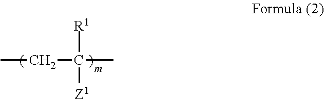
where R1 indicates a hydrogen atom, a halogen atom or a lower alkyl group, Z1 indicates a hydrogen atom, a lower alkyl group, a perfluoroalkyl group, an alkyloxy group, a phenyl group substituted by a halogen atom, a lower alkyl group substituted by a halogen atom, an alkyloxy group substituted by a halogen atom, a cyano group, or a group represented by —COOY1 (where Y1 indicates a hydrogen atom or a hydrocarbon group), and m indicates an integer of 1 to 500.

where R2 indicates a hydrogen atom, a halogen atom or a lower alkyl group, Z2 indicates a hydrogen atom, a lower alkyl group, a perfluoroalkyl group, an alkyloxy group, a phenyl group substituted by a halogen atom, a lower alkyl group substituted by a halogen atom, an alkyloxy group substituted by a halogen atom, a cyano group, or a group represented by —COOY2 (where Y2 indicates a hydrogen atom or a hydrocarbon group), p indicates an integer of 1 to 500, and q indicates an integer of 10 to 500. R3 and R4 each indicate a straight-chain, branched, or ring low molecular chain.

where R5 and R6 each independently indicate a hydrogen atom, a halogen atom or a lower alkyl group, Z3 and Z4 each independently indicate a hydrogen atom, a lower alkyl group, a perfluoroalkyl group, an alkyloxy group, a phenyl group substituted by a halogen atom, a lower alkyl group substituted by a halogen atom, an alkyloxy group substituted by a halogen atom, a cyano group, or a group represented by —COOY3 (where indicates Y3 indicates a hydrogen atom or a hydrocarbon group). r and s each independently indicate an integer of 1 to 500, and t indicates an integer of 10 to 500. R7, R8 and R9 each independently indicate a straight-chain, branched, or ring low molecular chain.
- 1 FIRST LIGHT TRANSMITTING PLATE
- 2 SECOND LIGHT TRANSMITTING PLATE
- 3 THERMOCHROMIC RESIN COMPOSITE
- 4 SEALING MATERIAL
- 10 AMPHIPHILIC LINEAR POLYMER
- 11 HYDROPHILIC UNIT
- 12 HYDROPHOBIC UNIT
- 20 AMPHIPHILIC ENDLESS POLYMER
- 21 HYDROPHILIC UNIT
- 22 HYDROPHOBIC UNIT
- 51 MIXED ASSOCIATE
- 52 MIXED AGGREGATE
- 100 DIMMER
Claims (9)


Applications Claiming Priority (3)
| Application Number | Priority Date | Filing Date | Title |
|---|---|---|---|
| JP2010145198 | 2010-06-25 | ||
| JP2010-145198 | 2010-06-25 | ||
| PCT/JP2011/003516 WO2011161940A1 (en) | 2010-06-25 | 2011-06-21 | Thermochromic resin composition, method for adjusting clouding point of thermochromic resin composition, and dimmer |
Publications (2)
| Publication Number | Publication Date |
|---|---|
| US20130092888A1 US20130092888A1 (en) | 2013-04-18 |
| US9256010B2 true US9256010B2 (en) | 2016-02-09 |
Family
ID=45371147
Family Applications (1)
| Application Number | Title | Priority Date | Filing Date |
|---|---|---|---|
| US13/806,035 Expired - Fee Related US9256010B2 (en) | 2010-06-25 | 2011-06-21 | Thermochromic resin composite, method for adjusting clouding point of thermochromic resin composite, and dimmer |
Country Status (4)
| Country | Link |
|---|---|
| US (1) | US9256010B2 (en) |
| EP (1) | EP2586833A4 (en) |
| JP (1) | JPWO2011161940A1 (en) |
| WO (1) | WO2011161940A1 (en) |
Families Citing this family (3)
| Publication number | Priority date | Publication date | Assignee | Title |
|---|---|---|---|---|
| JP6384247B2 (en) * | 2014-10-03 | 2018-09-05 | コニカミノルタ株式会社 | Optical film and optical film manufacturing method |
| CN106773234B (en) * | 2016-12-16 | 2019-10-29 | 北京大学 | A kind of temperature control light modulation film and preparation method thereof with shielding near infrared light function |
| CN111303608B (en) * | 2020-02-28 | 2022-05-20 | 珀力玛新材料(苏州)有限公司 | Temperature-change dimming fireproof material and preparation method and application thereof |
Citations (4)
| Publication number | Priority date | Publication date | Assignee | Title |
|---|---|---|---|---|
| US5188760A (en) | 1990-04-06 | 1993-02-23 | U. S. Philips Corporation | Liquid crystalline material and display cell containing said material |
| JP2000155345A (en) | 1998-11-24 | 2000-06-06 | Affinity Kk | Window using light controlling glass |
| JP2000354952A (en) | 1999-04-05 | 2000-12-26 | Nikon Corp | Polishing member, polishing method, polishing apparatus, semiconductor device manufacturing method, and semiconductor device |
| JP2001354952A (en) * | 2000-06-13 | 2001-12-25 | Central Glass Co Ltd | Production method for thermochromic material, and dimmer using the same |
Family Cites Families (6)
| Publication number | Priority date | Publication date | Assignee | Title |
|---|---|---|---|---|
| JPH06293809A (en) * | 1992-05-19 | 1994-10-21 | Noriyuki Kuramoto | Temperature-sensitive polymer material |
| JPH08165396A (en) * | 1994-12-14 | 1996-06-25 | Kurabe Ind Co Ltd | Thermochromic resin composition |
| JP4003811B2 (en) * | 1997-09-12 | 2007-11-07 | 独立行政法人科学技術振興機構 | Novel production method of cyclic polymer and novel cyclic polymer |
| JP2000344834A (en) * | 1999-06-09 | 2000-12-12 | Amersham Pharmacia Biotech Kk | Polymer compound having temperature response |
| JP2001337353A (en) * | 2000-05-30 | 2001-12-07 | Central Glass Co Ltd | Dimming body and its manufacturing method |
| WO2005105874A1 (en) * | 2004-04-30 | 2005-11-10 | Polymers Australia Pty Limited | Photochromic compositions and articles comprising polyether oligomer |
-
2011
- 2011-06-21 JP JP2012521320A patent/JPWO2011161940A1/en not_active Withdrawn
- 2011-06-21 WO PCT/JP2011/003516 patent/WO2011161940A1/en not_active Ceased
- 2011-06-21 US US13/806,035 patent/US9256010B2/en not_active Expired - Fee Related
- 2011-06-21 EP EP11797829.6A patent/EP2586833A4/en not_active Withdrawn
Patent Citations (4)
| Publication number | Priority date | Publication date | Assignee | Title |
|---|---|---|---|---|
| US5188760A (en) | 1990-04-06 | 1993-02-23 | U. S. Philips Corporation | Liquid crystalline material and display cell containing said material |
| JP2000155345A (en) | 1998-11-24 | 2000-06-06 | Affinity Kk | Window using light controlling glass |
| JP2000354952A (en) | 1999-04-05 | 2000-12-26 | Nikon Corp | Polishing member, polishing method, polishing apparatus, semiconductor device manufacturing method, and semiconductor device |
| JP2001354952A (en) * | 2000-06-13 | 2001-12-25 | Central Glass Co Ltd | Production method for thermochromic material, and dimmer using the same |
Non-Patent Citations (5)
| Title |
|---|
| Adachi et al, ATRP-RCM Synthesis of Cyclic Diblock Copolymers, Oct. 8, 2008, Macromolecules, 41, 7898-7903. * |
| Adachi, et al., "ATRP-RCM Synthesis of Cyclic Diblock Copolymers", Macromolecules, vol. 41, pp. 7896-7903, 2008. |
| Adachi, et al., "ATRP-RCM Synthesis of Cyclic Diblock Copolymers", Macromolecules, vol. 41, pp. 7898-7903, 2008 (Supporting Information). |
| International Search Report dated Aug. 16, 2011, as issued in corresponding International Patent Application No. PCT/JP2011/003516, filed Jun. 21, 2011. |
| Kuramasu et al, JP 2001-354952 Machine Translation, Dec. 25, 2001. * |
Also Published As
| Publication number | Publication date |
|---|---|
| EP2586833A4 (en) | 2015-09-09 |
| JPWO2011161940A1 (en) | 2013-08-19 |
| US20130092888A1 (en) | 2013-04-18 |
| EP2586833A1 (en) | 2013-05-01 |
| WO2011161940A1 (en) | 2011-12-29 |
Similar Documents
| Publication | Publication Date | Title |
|---|---|---|
| Song et al. | Hierarchical photonic pigments via the confined self-assembly of bottlebrush block copolymers | |
| CN104641282B (en) | Liquid crystal device | |
| JP6551536B2 (en) | Liquid crystal element | |
| JP7070429B2 (en) | Reverse mode LCD device | |
| Zhang et al. | Core cross-linked multiarm star polymers with aggregation-induced emission and temperature responsive fluorescence characteristics | |
| Tan et al. | Tailoring micelle formation and gelation in (PEG− P (MA-POSS)) amphiphilic hybrid block copolymers | |
| US9256010B2 (en) | Thermochromic resin composite, method for adjusting clouding point of thermochromic resin composite, and dimmer | |
| US20250314941A1 (en) | Optical activation of chemical entities in electrophoretic dispersions for display devices | |
| TWI681041B (en) | Liquid crystal display device and liquid crystal composition used therefor | |
| Pan et al. | Star mesogen-jacketed liquid crystalline polymers with silsesquioxane core: synthesis and characterization | |
| JP2021505937A (en) | Liquid crystal cell | |
| Ndaya et al. | Spherical photonic nanostructures from high molecular weight liquid crystalline brushlike block copolymers | |
| CN104094159A (en) | Ink for electrowetting elements, and electrowetting device using same | |
| JP2018522260A (en) | Liquid crystal cell | |
| JP2011123238A (en) | Display element | |
| TW201241074A (en) | Resin composition, phase-contrast film, method for manufacturing phase-contrast film, and long circularly-polarizing plate | |
| Kim et al. | Fluorescent supracolloidal chains of patchy micelles of diblock copolymers functionalized with fluorophores | |
| Wei et al. | Synthesis, characterization, and photo‐responsive properties of Y‐shaped amphiphilic azo triblock copolymer | |
| Shinohara et al. | Solvent-free conjugated polymer fluids with optical functions | |
| De Santis et al. | On the upper critical solution temperature of PNIPAAM in an ionic liquid: Effect of molecular weight, tacticity and water | |
| KR101952696B1 (en) | Dispersion of phonic crystalic particles and preparing method of the same, and photonic crystal display device including the same | |
| JP7267283B2 (en) | Variable opacity material passively driven by heat | |
| JP2010126623A (en) | Dispersion resin composition, curable composition and film for suspended particle device | |
| KR102118362B1 (en) | Precursor composition for liquid crystal layer | |
| JP2020139135A (en) | Cholesteric liquid crystal polymer fine particles having a radial spiral molecular orientation structure, cholesteric liquid crystal structure, method for producing cholesteric liquid crystal polymer fine particles, and method for using dispersion stabilizer. |
Legal Events
| Date | Code | Title | Description |
|---|---|---|---|
| AS | Assignment |
Owner name: TOKYO INSTITUTE OF TECHNOLOGY, JAPAN Free format text: ASSIGNMENT OF ASSIGNORS INTEREST;ASSIGNORS:HONDA, SATOSHI;YAMAMOTO, TAKUYA;TEZUKA, YASUYUKI;REEL/FRAME:029512/0871 Effective date: 20121127 |
|
| STCF | Information on status: patent grant |
Free format text: PATENTED CASE |
|
| FEPP | Fee payment procedure |
Free format text: MAINTENANCE FEE REMINDER MAILED (ORIGINAL EVENT CODE: REM.); ENTITY STATUS OF PATENT OWNER: SMALL ENTITY |
|
| LAPS | Lapse for failure to pay maintenance fees |
Free format text: PATENT EXPIRED FOR FAILURE TO PAY MAINTENANCE FEES (ORIGINAL EVENT CODE: EXP.); ENTITY STATUS OF PATENT OWNER: SMALL ENTITY |
|
| STCH | Information on status: patent discontinuation |
Free format text: PATENT EXPIRED DUE TO NONPAYMENT OF MAINTENANCE FEES UNDER 37 CFR 1.362 |
|
| FP | Lapsed due to failure to pay maintenance fee |
Effective date: 20200209 |