US9255422B1 - Lead and particulate abatement system - Google Patents
Lead and particulate abatement system Download PDFInfo
- Publication number
- US9255422B1 US9255422B1 US13/433,122 US201213433122A US9255422B1 US 9255422 B1 US9255422 B1 US 9255422B1 US 201213433122 A US201213433122 A US 201213433122A US 9255422 B1 US9255422 B1 US 9255422B1
- Authority
- US
- United States
- Prior art keywords
- container
- encapsulating
- work
- lead
- adjustable
- Prior art date
- Legal status (The legal status is an assumption and is not a legal conclusion. Google has not performed a legal analysis and makes no representation as to the accuracy of the status listed.)
- Expired - Fee Related, expires
Links
- 239000000428 dust Substances 0.000 claims abstract description 24
- 238000009418 renovation Methods 0.000 claims abstract description 17
- 230000008439 repair process Effects 0.000 claims abstract description 13
- 238000009432 framing Methods 0.000 claims abstract description 11
- 239000002245 particle Substances 0.000 claims abstract description 11
- 230000007246 mechanism Effects 0.000 claims abstract description 10
- 229920002457 flexible plastic Polymers 0.000 claims abstract description 7
- 230000000116 mitigating effect Effects 0.000 claims abstract description 7
- 238000010276 construction Methods 0.000 claims abstract description 6
- 239000000383 hazardous chemical Substances 0.000 claims abstract description 6
- 206010072063 Exposure to lead Diseases 0.000 claims abstract description 4
- 238000011109 contamination Methods 0.000 claims abstract description 3
- 239000004033 plastic Substances 0.000 claims description 10
- 229920003023 plastic Polymers 0.000 claims description 10
- 239000000463 material Substances 0.000 claims description 9
- 238000007789 sealing Methods 0.000 claims description 9
- 238000005067 remediation Methods 0.000 claims description 8
- 231100001261 hazardous Toxicity 0.000 claims description 5
- 229920001169 thermoplastic Polymers 0.000 claims description 4
- 239000004416 thermosoftening plastic Substances 0.000 claims description 4
- 239000004820 Pressure-sensitive adhesive Substances 0.000 claims description 3
- 238000012423 maintenance Methods 0.000 claims description 2
- 238000000034 method Methods 0.000 description 20
- 239000000853 adhesive Substances 0.000 description 11
- 230000001070 adhesive effect Effects 0.000 description 11
- 238000013461 design Methods 0.000 description 11
- 239000003973 paint Substances 0.000 description 10
- 239000000356 contaminant Substances 0.000 description 7
- 238000009434 installation Methods 0.000 description 7
- 239000011087 paperboard Substances 0.000 description 6
- 230000008569 process Effects 0.000 description 5
- 239000011111 cardboard Substances 0.000 description 4
- 239000003595 mist Substances 0.000 description 3
- 230000008901 benefit Effects 0.000 description 2
- 238000010586 diagram Methods 0.000 description 2
- 210000002310 elbow joint Anatomy 0.000 description 2
- 230000007613 environmental effect Effects 0.000 description 2
- 239000000123 paper Substances 0.000 description 2
- 230000029058 respiratory gaseous exchange Effects 0.000 description 2
- 238000003860 storage Methods 0.000 description 2
- 238000011282 treatment Methods 0.000 description 2
- 229910000831 Steel Inorganic materials 0.000 description 1
- 238000010521 absorption reaction Methods 0.000 description 1
- 230000001154 acute effect Effects 0.000 description 1
- 239000002390 adhesive tape Substances 0.000 description 1
- 229910052782 aluminium Inorganic materials 0.000 description 1
- XAGFODPZIPBFFR-UHFFFAOYSA-N aluminium Chemical compound [Al] XAGFODPZIPBFFR-UHFFFAOYSA-N 0.000 description 1
- 230000004888 barrier function Effects 0.000 description 1
- 210000000133 brain stem Anatomy 0.000 description 1
- 238000005336 cracking Methods 0.000 description 1
- 230000000254 damaging effect Effects 0.000 description 1
- 230000007812 deficiency Effects 0.000 description 1
- 230000000694 effects Effects 0.000 description 1
- 230000008030 elimination Effects 0.000 description 1
- 238000003379 elimination reaction Methods 0.000 description 1
- 239000004519 grease Substances 0.000 description 1
- 238000004519 manufacturing process Methods 0.000 description 1
- 229910052751 metal Inorganic materials 0.000 description 1
- 239000002184 metal Substances 0.000 description 1
- 238000012986 modification Methods 0.000 description 1
- 230000004048 modification Effects 0.000 description 1
- 239000002991 molded plastic Substances 0.000 description 1
- 239000010813 municipal solid waste Substances 0.000 description 1
- 210000000653 nervous system Anatomy 0.000 description 1
- 230000001473 noxious effect Effects 0.000 description 1
- 238000010422 painting Methods 0.000 description 1
- 239000011505 plaster Substances 0.000 description 1
- 239000002985 plastic film Substances 0.000 description 1
- 229920006255 plastic film Polymers 0.000 description 1
- 238000009428 plumbing Methods 0.000 description 1
- 238000002360 preparation method Methods 0.000 description 1
- 238000007634 remodeling Methods 0.000 description 1
- 238000005096 rolling process Methods 0.000 description 1
- 239000002689 soil Substances 0.000 description 1
- 239000010959 steel Substances 0.000 description 1
- 230000009747 swallowing Effects 0.000 description 1
- 238000012549 training Methods 0.000 description 1
- 229920006352 transparent thermoplastic Polymers 0.000 description 1
Images


Classifications
-
- E—FIXED CONSTRUCTIONS
- E04—BUILDING
- E04H—BUILDINGS OR LIKE STRUCTURES FOR PARTICULAR PURPOSES; SWIMMING OR SPLASH BATHS OR POOLS; MASTS; FENCING; TENTS OR CANOPIES, IN GENERAL
- E04H15/00—Tents or canopies, in general
- E04H15/02—Tents combined or specially associated with other devices
- E04H15/10—Heating, lighting or ventilating
- E04H15/14—Ventilating
-
- E—FIXED CONSTRUCTIONS
- E04—BUILDING
- E04G—SCAFFOLDING; FORMS; SHUTTERING; BUILDING IMPLEMENTS OR AIDS, OR THEIR USE; HANDLING BUILDING MATERIALS ON THE SITE; REPAIRING, BREAKING-UP OR OTHER WORK ON EXISTING BUILDINGS
- E04G21/00—Preparing, conveying, or working-up building materials or building elements in situ; Other devices or measures for constructional work
- E04G21/24—Safety or protective measures preventing damage to building parts or finishing work during construction
- E04G21/243—Safety or protective measures preventing damage to building parts or finishing work during construction for creating a temporary partition in a closed room
-
- E—FIXED CONSTRUCTIONS
- E04—BUILDING
- E04G—SCAFFOLDING; FORMS; SHUTTERING; BUILDING IMPLEMENTS OR AIDS, OR THEIR USE; HANDLING BUILDING MATERIALS ON THE SITE; REPAIRING, BREAKING-UP OR OTHER WORK ON EXISTING BUILDINGS
- E04G21/00—Preparing, conveying, or working-up building materials or building elements in situ; Other devices or measures for constructional work
- E04G21/24—Safety or protective measures preventing damage to building parts or finishing work during construction
- E04G21/30—Safety or protective measures preventing damage to building parts or finishing work during construction against mechanical damage or dirt, e.g. guard covers of stairs
-
- E—FIXED CONSTRUCTIONS
- E04—BUILDING
- E04H—BUILDINGS OR LIKE STRUCTURES FOR PARTICULAR PURPOSES; SWIMMING OR SPLASH BATHS OR POOLS; MASTS; FENCING; TENTS OR CANOPIES, IN GENERAL
- E04H15/00—Tents or canopies, in general
- E04H15/32—Parts, components, construction details, accessories, interior equipment, specially adapted for tents, e.g. guy-line equipment, skirts, thresholds
- E04H15/34—Supporting means, e.g. frames
- E04H15/44—Supporting means, e.g. frames collapsible, e.g. breakdown type
- E04H15/46—Supporting means, e.g. frames collapsible, e.g. breakdown type telescoping and foldable
-
- E—FIXED CONSTRUCTIONS
- E04—BUILDING
- E04H—BUILDINGS OR LIKE STRUCTURES FOR PARTICULAR PURPOSES; SWIMMING OR SPLASH BATHS OR POOLS; MASTS; FENCING; TENTS OR CANOPIES, IN GENERAL
- E04H9/00—Buildings, groups of buildings or shelters adapted to withstand or provide protection against abnormal external influences, e.g. war-like action, earthquake or extreme climate
- E04H9/04—Buildings, groups of buildings or shelters adapted to withstand or provide protection against abnormal external influences, e.g. war-like action, earthquake or extreme climate against air-raid or other war-like actions
- E04H9/06—Structures arranged in or forming part of buildings
Definitions
- the present invention relates to a safe lead and/or particulate mitigation and clean-up system.
- Lead exposure is known as a hazard to young children and babies. Even children who seem healthy can have high levels of lead in their bodies from exposure to contaminated materials. Lead can be absorbed in the body by breathing or swallowing lead dust, or by eating soil or paint chips containing lead. In most cases, lead-based paint that is in good condition is not a hazard, but this does not ordinarily remain the case during renovations.
- Lead dust can form when lead-based paint is dry scraped, dry sanded, or heated. Dust also forms when painted surfaces rub together. Lead chips and dust can get on surfaces and objects that people touch. Settled lead dust can re-enter the air when people vacuum, sweep or walk through it.
- Removing lead-based paint improperly can increase the dangers of exposure to lead and lead dust.
- a trained and certified lead abatement contractor must be utilized.
- Abatement (or permanent hazard elimination) methods include removing, sealing, or enclosing lead-based paint with special materials. Painting over the hazard with regular paint is not sufficient, particularly during renovations which may require wholesale removal of large portions of building structures.
- the subject encapsulator design which utilizes a portable, adjustable, durable and flexible thermoplastic film barrier, preferably in the form of a large encapsulating pouch or workbag.
- the encapsulator workbag has its open end affixed to the area around a contaminated work-piece or work-area requiring repair, removal or renovation, and which effectively captures and encapsulates lead and particulate dust during removal and mitigation operations.
- the encapsulator system may incorporate a portable, adjustable frame apparatus configured to deploy an open encapsulator workbag at and around a work area requiring dust abatement.
- “Frame” is used broadly as the mechanism to facilitate deployment of the workbag by any means necessary to hold it in place during remediation, whereupon the contaminated workbag is removed upon completion of the renovation task.
- the frame may be configured with poles, scaffolding, a skeleton structure, a disposable platform and other convenient designs.
- the apparatus may comprise an adjustable frame apparatus having a plurality of height adjustable vertical poles or legs.
- the legs support a plurality of overhead horizontal frame members, the frame apparatus being adapted to surround a work-area encompassing a contaminated work-piece; a flexible plastic encapsulating container positioned within and supported by the adjustable frame apparatus.
- the container has at least one open-end for surrounding the contaminated work-piece, and the open-end of the container is adhered to the work-area and substantially surrounds the contaminated work-piece.
- the apparatus and system are effective for enclosing and containing hazardous lead-based materials during a construction repair, renovation or removal operation. The method is complete upon safe, clean disposal of the encapsulator container and contaminants therein.
- the encapsulating pouch or workbag may further comprise adhesive materials surrounding the open-end of the container; attachment fixtures for maintaining the flexible container by and within the adjustable frame; at least one entry/exit port separate from the open-end of the container and adapted to allow movement of an operator there through (and further comprising means such as a zipper for opening, closing and maintaining a seal).
- the opening of the workbag may be sealed around the work-piece with painter's adhesive tape.
- a useful optional accessory would be at least one filter device for dust-free removal of air to facilitate collapsing the flexible container when the mitigation project is complete; as well as at least one air-entry filter to facilitate maintenance of the flexible container shape during use and for providing fresh air to a user deployed therein.
- An alternative embodiment of the encapsulator apparatus is comprised of a plurality of height adjustable vertical legs or poles which use friction against the ceiling and floor of the work area to stand in place and to maintain the flexible plastic encapsulating container in an open position.
- spring clamps or ties may be used at either end of the adjustable legs to affix the encapsulating container.
- Spring poles, telescoping poles and cut-to-size poles may all be utilized.
- FIG. 1 is a schematic plan view of a window installation requiring lead abatement.
- FIG. 2 is a side elevation view of the encapsulator apparatus of the present invention.
- FIG. 3 is a top plan view of the apparatus of FIG. 2 .
- FIG. 4 is a front elevation view into an encapsulator apparatus, seen from outside a window installation.
- FIG. 5 is a rear elevation view of an alternative encapsulator apparatus having a rear entry/exit panel.
- FIG. 6 is a perspective view of an alternative encapsulator apparatus.
- FIG. 7 is an alternate embodiment of the subject design providing multiple encapsulator chambers.
- FIG. 8 is process flow chart depicting the subject system and method.
- FIG. 9 is a perspective view of an alternative encapsulator apparatus.
- FIG. 10 is a perspective view of the apparatus of FIG. 9 as deployed for a window installation.
- FIGS. 11 a - g is a diagram showing the method of unfolding the apparatus of FIG. 9 .
- FIGS. 12 a - b is a diagram showing the deployment of the apparatus of FIG. 9 .
- FIGS. 13A-13 c depict deployment of a further embodiment of the subject design.
- FIG. 14 is a perspective view of a portion of the alternative design seen in FIGS. 13A-C .
- FIG. 15 is a perspective view of the alternative encapsulator system deployed at a worksite for removal of fenestrations.
- FIG. 16 is a perspective detail of a portion of an alternative embodiment of the encapsulator system.
- FIG. 17 is a cross-sectional detail of a portion of a pole boot useful in some embodiments of the subject design.
- the proposed design is comprised of several parts which cooperate together for the purpose of collecting lead particles, chips, dust and other contaminants in reconstruction or restoration operations and minimizing exposure such hazardous materials.
- FIG. 1 depicts a schematic plan view of a window installation 1 requiring lead abatement.
- wall portion 12 has window 14 installed therein.
- Window 14 is encased in window frame members 15 , 16 , 17 and 18 , which in this example have been previously painted with lead-based paint which now requires repair or removal.
- the encapsulator system and apparatus which is shown and described in the following Figures will be attached or preferably adhered to at least horizontal adhesive area 19 , and may be additionally adhered to adhesive area 20 in the case of a window frame or casing restoration or repair, or also adhered to vertical adhesive areas 21 and 22 in the case of a door frame restoration or repair. Conventional painter's tape can be used for this purpose.
- FIG. 2 depicts a side elevation view of the encapsulator apparatus 30 of the present invention.
- adjustable vertical legs 40 , 41 and 42 are respectively joined to elbow junctions 39 , 38 and 37 to support upper horizontal frame members 33 and 32 .
- Fittings 36 , 35 and 34 support the vertical legs.
- the adjustable frame members contain and support a flexible plastic containment device, preferably a workbag or bladder for holding lead dust and particles, having rear section 2 , central section 4 and forward open section 6 to be adhered around and near the work piece located on or in wall section 31 , to receive contaminated lead chips, particles and dust during a repair, renovation or removal project.
- FIG. 3 depicts a top plan view of the apparatus 30 of FIG. 2 .
- the flexible encapsulator container having rear section 2 , center section 4 and front section 6 can be seen with and supported by the encapsulator frame apparatus.
- elbow joints 38 and 38 a can be seen as connected via adjustable frame members 43 and 44 and cross joint 38 b .
- a parallel portion of the frame apparatus consisting of elbow joints 37 and 37 a which are connected via adjustable frame members 45 and 46 and t-joint 37 b .
- Front flexible section 6 is seen adhered to work-area wall section 31 at the front of the apparatus.
- optional port 2 a is seen which may be a filter, air supply or entry/exit portal. In many embodiments, an optional zipper may be installed for entry and exit.
- FIG. 4 is a front elevation view into an encapsulator apparatus 40 , seen from outside a window installation 1 , that is looking into wall portion 42 which has on its inside surface adhesive area 49 surrounding the work-piece to be repaired or removed.
- Adjustable frame members 45 , 46 and adjustable legs 40 support the flexible film container 48 throughout the remediation procedure.
- FIG. 5 is a rear elevation view of an alternative encapsulator apparatus 50 , having frame members 52 , 54 , 56 and 58 and having a rear entry/exit panel 62 installed in the rear section of flexible film container 60 .
- FIG. 6 is a perspective view of an alternative encapsulator apparatus 65 depicted installed on wall section 66 surrounding window 69 and attached with adhesive to surrounding areas 70 .
- the adjustable encapsulator frame members are 68 , 72 , 74 , 76 , 78 and 79 . This embodiment may be suitable for smaller renovation projects.
- FIG. 7 is an alternate embodiment of the subject design providing multiple encapsulator chambers. Under appropriate circumstances, an entire room area can be remediated with the equipment and method of the subject invention.
- each of three independent window work-pieces A, B and C can accommodate respective work areas a, b and c for collecting lead, dust and other hazardous materials from each work piece.
- a relatively clean central staging area can coordinate activities for each work piece which can be reached via clean-passageways a′, b′ and c′.
- the staging area can have its own entry, in this case a flap fold to facilitate keeping the remainder of the room clean and contaminant free.
- FIG. 8 is process flow chart depicting the subject system and method. The method comprises the steps of: first, adjusting an encapsulator system in proximity with a contaminated work-piece ( 82 ), this is typically accomplished with an adjustable or fixed pole or frame; deploying an encapsulator container (i.e.
- FIG. 9 is an alternative embodiment 100 of the subject apparatus using only the adjustable height vertical legs 102 as support for the flexible film encapsulator workbag or bladder 101 .
- the adjustable height vertical legs may be adjustable using any means of varying the length of a structural member, including spring loaded, or held in place using friction, screws or pins.
- the vertical leg has a base 104 for supporting the leg while it stands, and a top plate 103 for holding the encapsulator film 101 against the ceiling of the work area.
- the encapsulator film 101 has opening 110 which would be directed towards the area requiring abatement.
- the side flaps 105 would be folded inwards, and top flap 107 and bottom flap 108 would be folded down and up respectively, so that tape areas 106 may be secured against the wall 111 surrounding the work area.
- Alternative embodiments deploy the adjustable poles in place directly between the ceiling and floor and thereafter secure the encapsulator film container thereto with spring clamps, ties and the like.
- FIG. 10 shows the alternative embodiment 100 of the subject apparatus of FIG. 9 as deployed in a work area surrounding a window 120 .
- the encapsulator container opening is preferably sealed around the window work area with pressure-sensitive adhesive or tape.
- This figure additionally depicts use of zipper entry 300 in one side wall of the container.
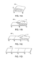
- FIGS. 11 a - g show the method of deploying a flexible encapsulator film workbag or bladder 200 .
- the bag upon manufacture or storage, the bag will be folded such that the process of unfolding the bag 200 will comprise the following steps: first, placing edge A on the ground as in FIG. 11 a , pass edge C over fold B as in FIG. 11 b ; then pass edge D over fold C as in FIG. 11 c ; then finally pass edge E over fold D as in FIG. 11 d .
- lengthwise edge G is passed over fold F
- edge J is passed over fold H, so that the entire encapsulator film bag is laying flat on the ground as in FIG. 11 g .
- the encapsulator film workbag then can be readily deployed within a set of adjustable poles, or incorporated in a skeletal frame structure.
- the top 205 of the encapsulator film workbag is lifted, thus creating working and collection space within the bag 200 to be deployed in a work area.
- Adjustable height vertical legs 201 are used to press the upper corners 203 of the bag 200 against a ceiling and using friction hold the bag 200 in place in a work area.
- suitable workbag containers will be fabricated from webs of thermoplastic film formed into gusseted bags having a seal at one end and an opening at the opposite end.
- the frame mechanism utilized to deploy and hold open the workbag at the work-piece location also can be strings or line, taped, clipped or secured to edges of the workbag and then tied off at suitable secure positions effective for holding the workbag in place.
- FIGS. 13 a - 13 c depict deployment of a further embodiment 400 of the subject design wherein paperboard platform 410 is initially folded to contain an encapsulator workbag 412 .
- the built-in posts 422 , 424 , 426 and 428 are revealed within the workbag 412 .
- posts can be included within the assembly and folded outward and upward in operation, or posts may be added separately.
- FIG. 14 is a perspective view of a portion of an alternative design 420 wherein paperboard platform 430 is deployed horizontally upon a floor and foldable legs 422 , 424 , 426 and 428 are raised with hinges to upright positions for holding the upper parts of the encapsulator workbag.
- the workbag opening is to the right hand side where flap 432 can be seen.
- FIG. 15 is a perspective view of the alternative encapsulator system 450 deployed at a worksite for removal of fenestrations.
- the encapsulator system 450 is fully deployed for removal or remediation of fenestrations 462 , 463 in wall 460 .
- an access point is provided by a zipper 470 secured to film wall 452 with adhesive such as 3M Blue Painter's Tape.
- FIG. 16 is a perspective view of encapsulator platform base 500 which in this example is approximately 3 ⁇ 8 in. thick corrugated paperboard 510 .
- encapsulator platform base 500 which in this example is approximately 3 ⁇ 8 in. thick corrugated paperboard 510 .
- post boots 522 , 524 , 526 and 528 for subsequent erection of workbag bearing poles.
- an aperture 530 for holding the posts.
- the post boots may be fashioned from paperboard or molded plastics as desired.
- FIG. 17 is a cross-sectional detail of alternative embodiment 540 , showing a portion of pole boot 550 useful in some embodiments of the subject design.
- a portion of workbag film 560 is shown in exaggerated detail, held within boot by the weight and friction provided by pole 570 .
- the encapsulator film bag may be used without any separate structural frame, if the upper corners of the bag are securely attached to a ceiling by any means of attachment, including trussing with cord or line of sufficient length and strength to hold the encapsulator bag in position.
- the ceiling attachment and line act as the framing mechanism.
- a corrugated containerboard (paperboard) platform of various sizes (e.g. 4 ⁇ 6, 6 ⁇ 6, or 10 ⁇ 6 ft) may be provided. It is preferably foldable at 2 ft increments and contains a 3 mil plastic workbag of matching dimensions and having four circular cardboard poles or similar rectangular cardboard posts that would fit inside circular cardboard footings attached to the platform pinching the bag into the receiver hole with the base of the circular pole. The cardboard platform is used outside the bag while the poles that fit inside the footings are inside the bag. Paperboard poles of circular tubing and having various fixed, adjustable or ready-to-cut lengths (e.g. 7-9 ft) may be provided in typical remediation applications.
- paperboard poles of circular tubing and having various fixed, adjustable or ready-to-cut lengths e.g. 7-9 ft
- the system framing members can be made from a wide range of materials and sizes. Most preferred will be adjustable metal members such as aluminum or steel poles and horizontal framing pieces. For other installations, PVC tubing and plumbing joints can be satisfactory. For simpler installations, even adjustable lumber with bolts and wing nuts can be utilized. Telescoping poles of varying lengths, using snap, screw or friction fittings are particularly useful in connection with the present system.
- the flexible thermoplastic film container be made of a rugged, transparent thermoplastic sheet such as saran and similar sheet films of sufficient thickness and durability, of at least one mil with a preferred thickness of at least 2 mil to 20 mil or more, such that it can withstand any strains imposed by seams, storage, transport, as well as during intended use with the poles, frame or a worker therein, and will safely contain all necessary lead chips, particles, dust and contaminated debris. Thicknesses of 3 mil to 6 mil are preferred in many applications. Less than 2 mil sheets are not sufficiently resilient and sheets thicker than 6 mil become difficult to handle in ordinary applications. Preferred plastic films may also have electrostatic properties which facilitate attraction and adherence of dust particles thereto.
- the encapsulator workbags may additionally incorporate pressure sensitive adhesives for sealing around a work piece, or such sealing may be accomplished by sealing tape and related methods.
- the method and apparatus may be utilized as follows.
- the workbag can be installed on sheetrock, wallpaper, wallboard, tile, plaster or veneer surfaces and the like, however, it is not to be installed upon the window, door or casing that is to be removed.
- the selected surface is prepared until it is dry, clean, oil free and grease free.
- the interior setup may be installed as follows. 1. Unfold the workbag with open its end facing the fenestration (window or door). 2. Position two front poles on opposite sides of the open end of the bag. 3. Measure the ceiling height and divide height in half to determine placement of poles on workbag. For example, for an 8 ft ceiling, attach poles 4 ft in from the sides of the workbag to achieve the proper amount of slack from floor to ceiling. 4. Adjustable poles should be outside of the bag, not inside. Attach the head of the adjustable poles over the outside of the bag, placing the head of the poles approximately 16 inches in from the edge of the open end of the bag, leaving approximately 12 inches of slack hanging loosely. 5.
- a replaceable zipper is utilized to facilitate entry and exit from the deployed workbag. Select where the zippered opening location is intended and be sure the plastic is clean and the area is sufficient for the length of the zipper. Then peel the release paper from the back of the zipper at the top and press the zipper onto the plastic. Remove the paper as the zipper is pressed onto the plastic, keeping it as straight as possible. At the bottom of the zipper, separate the two sides of the zipper to be sure both pulls are free of the adhesive. The inside pull should not be stuck to the zipper. Carefully unzip the zipper completely and use the opening as a guide to cut the plastic thereby creating an entry to the interior of the workbag.
- a worker enters the workbag and closes the zipper. Seal the slack of the workbag around the fenestration, (window or door) using painter's tape. Two inch tape minimum is recommended. Starting from the floor of the workbag, seal the open end of the workbag to the wall or edge of floor. Moving clockwise around the fenestration, be sure to seal the workbag above, below and on all sides to ensure an airtight seal between the edges of the workbag and the surface of the wall around the fenestration that is to be removed. Overlapping the corners of the interior slack, thereby creating “Hospital corners” is recommended. Begin work, remediation or renovation as usual.
Abstract
Description
Claims (12)
Priority Applications (1)
| Application Number | Priority Date | Filing Date | Title |
|---|---|---|---|
| US13/433,122 US9255422B1 (en) | 2011-03-28 | 2012-03-28 | Lead and particulate abatement system |
Applications Claiming Priority (3)
| Application Number | Priority Date | Filing Date | Title |
|---|---|---|---|
| US201161468394P | 2011-03-28 | 2011-03-28 | |
| US201161562298P | 2011-11-21 | 2011-11-21 | |
| US13/433,122 US9255422B1 (en) | 2011-03-28 | 2012-03-28 | Lead and particulate abatement system |
Publications (1)
| Publication Number | Publication Date |
|---|---|
| US9255422B1 true US9255422B1 (en) | 2016-02-09 |
Family
ID=55235527
Family Applications (1)
| Application Number | Title | Priority Date | Filing Date |
|---|---|---|---|
| US13/433,122 Expired - Fee Related US9255422B1 (en) | 2011-03-28 | 2012-03-28 | Lead and particulate abatement system |
Country Status (1)
| Country | Link |
|---|---|
| US (1) | US9255422B1 (en) |
Cited By (3)
| Publication number | Priority date | Publication date | Assignee | Title |
|---|---|---|---|---|
| US9391711B1 (en) * | 2013-07-11 | 2016-07-12 | Inphi Corporation | Integrated control module for communication system on a chip for silicon photonics |
| CN106126694A (en) * | 2016-06-30 | 2016-11-16 | 中国科学院烟台海岸带研究所 | The support of a kind of impurely Rehabilitation decision and the construction method of online evaluation platform |
| JP2020084727A (en) * | 2018-11-30 | 2020-06-04 | 株式会社ダスキン | Upper floor indoor antifouling device used in underfloor work |
Citations (21)
| Publication number | Priority date | Publication date | Assignee | Title |
|---|---|---|---|---|
| US4682448A (en) * | 1986-03-21 | 1987-07-28 | Fiberlock Technologies, Inc. | Shelter |
| US4706551A (en) * | 1984-09-20 | 1987-11-17 | Schofield Paul S | Enclosure |
| US4765352A (en) * | 1987-07-17 | 1988-08-23 | Strieter Jerome F | Portable isolation enclosure for use in cleaning contaminated environments |
| US4786296A (en) | 1987-06-23 | 1988-11-22 | Griffis Steven C | Apparatus for use in asbestos removal |
| US4800908A (en) | 1988-01-07 | 1989-01-31 | Lyons William G | Taped troughs for wet removal of asbestos |
| US4817644A (en) | 1986-10-17 | 1989-04-04 | Envirosafe Corp. | Apparatus and method for the safe and effective, large scale removal and disposal of hazardous materials from building components |
| US4853042A (en) | 1987-06-29 | 1989-08-01 | General Maintenance Company, Inc. | Process for removing asbestos or other friable coating from a surface |
| US4857085A (en) | 1988-05-20 | 1989-08-15 | Egri Ii John D | Process for abatement of asbestos fibers |
| US5004483A (en) | 1990-04-25 | 1991-04-02 | Enviro-Air Control Corporation | Particulate abatement and environmental control system |
| US5062871A (en) * | 1989-11-13 | 1991-11-05 | Seth C. Hunt | System for localizing a portion of a structure for treatment |
| US5080701A (en) | 1990-12-19 | 1992-01-14 | Commercial Decontamination, Inc. | Portable decontamination unit for spot abatement of asbestos or similar contaminants |
| US5131934A (en) | 1991-09-27 | 1992-07-21 | Union Carbide Chemicals & Plastics Technology Corporation | Apparatus for removing hazardous particulate and fibrous materials |
| US5332095A (en) * | 1993-11-02 | 1994-07-26 | Hans Wu | Bag with means for vacuuming an internal space thereof |
| US5685112A (en) * | 1994-09-29 | 1997-11-11 | Fara; Mark C. | Apparatus and method for removing structural parts of a building without contaminating adjacent areas |
| US5924469A (en) * | 1996-10-29 | 1999-07-20 | Zipwall, Llc | Partition mount |
| US20040050008A1 (en) * | 2002-07-26 | 2004-03-18 | Mintie Kevin J. | Environmental control unit |
| US7188636B1 (en) * | 2004-04-14 | 2007-03-13 | Steve Kanne | Containment cart |
| US20090032204A1 (en) * | 2007-08-01 | 2009-02-05 | Mintie Kevin J | Corridor flange |
| US20100058674A1 (en) * | 2008-09-08 | 2010-03-11 | Kelly Lewis Proctor | Mobile environment containment unit |
| US8397958B2 (en) * | 2010-08-05 | 2013-03-19 | Ds Smith Plastics Limited | Closure valve assembly for a container |
| US8590229B2 (en) * | 2010-09-15 | 2013-11-26 | Shurtech Brands, Llc | Inflatable attic stairway insulation appliance |
-
2012
- 2012-03-28 US US13/433,122 patent/US9255422B1/en not_active Expired - Fee Related
Patent Citations (21)
| Publication number | Priority date | Publication date | Assignee | Title |
|---|---|---|---|---|
| US4706551A (en) * | 1984-09-20 | 1987-11-17 | Schofield Paul S | Enclosure |
| US4682448A (en) * | 1986-03-21 | 1987-07-28 | Fiberlock Technologies, Inc. | Shelter |
| US4817644A (en) | 1986-10-17 | 1989-04-04 | Envirosafe Corp. | Apparatus and method for the safe and effective, large scale removal and disposal of hazardous materials from building components |
| US4786296A (en) | 1987-06-23 | 1988-11-22 | Griffis Steven C | Apparatus for use in asbestos removal |
| US4853042A (en) | 1987-06-29 | 1989-08-01 | General Maintenance Company, Inc. | Process for removing asbestos or other friable coating from a surface |
| US4765352A (en) * | 1987-07-17 | 1988-08-23 | Strieter Jerome F | Portable isolation enclosure for use in cleaning contaminated environments |
| US4800908A (en) | 1988-01-07 | 1989-01-31 | Lyons William G | Taped troughs for wet removal of asbestos |
| US4857085A (en) | 1988-05-20 | 1989-08-15 | Egri Ii John D | Process for abatement of asbestos fibers |
| US5062871A (en) * | 1989-11-13 | 1991-11-05 | Seth C. Hunt | System for localizing a portion of a structure for treatment |
| US5004483A (en) | 1990-04-25 | 1991-04-02 | Enviro-Air Control Corporation | Particulate abatement and environmental control system |
| US5080701A (en) | 1990-12-19 | 1992-01-14 | Commercial Decontamination, Inc. | Portable decontamination unit for spot abatement of asbestos or similar contaminants |
| US5131934A (en) | 1991-09-27 | 1992-07-21 | Union Carbide Chemicals & Plastics Technology Corporation | Apparatus for removing hazardous particulate and fibrous materials |
| US5332095A (en) * | 1993-11-02 | 1994-07-26 | Hans Wu | Bag with means for vacuuming an internal space thereof |
| US5685112A (en) * | 1994-09-29 | 1997-11-11 | Fara; Mark C. | Apparatus and method for removing structural parts of a building without contaminating adjacent areas |
| US5924469A (en) * | 1996-10-29 | 1999-07-20 | Zipwall, Llc | Partition mount |
| US20040050008A1 (en) * | 2002-07-26 | 2004-03-18 | Mintie Kevin J. | Environmental control unit |
| US7188636B1 (en) * | 2004-04-14 | 2007-03-13 | Steve Kanne | Containment cart |
| US20090032204A1 (en) * | 2007-08-01 | 2009-02-05 | Mintie Kevin J | Corridor flange |
| US20100058674A1 (en) * | 2008-09-08 | 2010-03-11 | Kelly Lewis Proctor | Mobile environment containment unit |
| US8397958B2 (en) * | 2010-08-05 | 2013-03-19 | Ds Smith Plastics Limited | Closure valve assembly for a container |
| US8590229B2 (en) * | 2010-09-15 | 2013-11-26 | Shurtech Brands, Llc | Inflatable attic stairway insulation appliance |
Cited By (6)
| Publication number | Priority date | Publication date | Assignee | Title |
|---|---|---|---|---|
| US9391711B1 (en) * | 2013-07-11 | 2016-07-12 | Inphi Corporation | Integrated control module for communication system on a chip for silicon photonics |
| US9515764B2 (en) * | 2013-07-11 | 2016-12-06 | Inphi Corporation | Integrated control module for communication system on a chip for silicon photonics |
| US20170070294A1 (en) * | 2013-07-11 | 2017-03-09 | Inphi Corporation | Integrated control module for communication system-on-a-chip for silicon photonics |
| US9621273B2 (en) * | 2013-07-11 | 2017-04-11 | Inphi Corporation | Integrated control module for communication system-on-a-chip for silicon photonics |
| CN106126694A (en) * | 2016-06-30 | 2016-11-16 | 中国科学院烟台海岸带研究所 | The support of a kind of impurely Rehabilitation decision and the construction method of online evaluation platform |
| JP2020084727A (en) * | 2018-11-30 | 2020-06-04 | 株式会社ダスキン | Upper floor indoor antifouling device used in underfloor work |
Similar Documents
| Publication | Publication Date | Title |
|---|---|---|
| US5685112A (en) | Apparatus and method for removing structural parts of a building without contaminating adjacent areas | |
| US5062871A (en) | System for localizing a portion of a structure for treatment | |
| US10039681B2 (en) | Isolation method and apparatus | |
| US6973997B2 (en) | Pollution containment apparatus for making a penetration in a ceiling or wall of a building or other structure | |
| US4883512A (en) | Portable isolation enclosure | |
| US6383242B1 (en) | Mobile enclosure unit | |
| US9255422B1 (en) | Lead and particulate abatement system | |
| EP2537600B1 (en) | Environmental containment unit and method for isolating a work area. | |
| US6865850B1 (en) | Temporary protective shrouds for protecting windows and fixtures during construction | |
| US8234822B2 (en) | Mobile environment containment unit | |
| US5457922A (en) | Apparatus and method for removing structural parts of a building without contaminating adjacent areas | |
| CA2970032A1 (en) | Multi-use icra booth | |
| US20160207704A1 (en) | Collapsible Containment Bag | |
| US8137156B1 (en) | Enclosure apparatus and method | |
| US20130008620A1 (en) | Adjustable enclosure and method for enclosing a work space having a surface therein to be worked upon, the surface bearing a lead-based paint | |
| US20070107355A1 (en) | Window shroud system | |
| US7818941B2 (en) | Plastic sheet barrier enclosure, system, and method | |
| WO2016147061A1 (en) | Portable decontamination device and method of using it | |
| US20160145857A1 (en) | Elastomeric flashing assembly and method for same | |
| US20120027975A1 (en) | Method and apparatus for toxic substance encapsulation | |
| US9598873B1 (en) | Temporary portable abatement, remediation, demolition, and remodeling door | |
| KR101975738B1 (en) | Dust layer for preventing paint mist scattering | |
| US20080282615A1 (en) | Window opening protector | |
| JP7306817B2 (en) | Above-floor indoor antifouling device used for below-floor work | |
| TWM474778U (en) | Improved working scaffold horizontal deckstructure with stepping up and down device and hand rail |
Legal Events
| Date | Code | Title | Description |
|---|---|---|---|
| AS | Assignment |
Owner name: ENCAPSULATOR, LLC, NEW YORK Free format text: ASSIGNMENT OF ASSIGNORS INTEREST;ASSIGNORS:WAGNER, WILLIAM E;FERSTAND, ADAM J;REEL/FRAME:027949/0597 Effective date: 20120328 |
|
| ZAAA | Notice of allowance and fees due |
Free format text: ORIGINAL CODE: NOA |
|
| ZAAB | Notice of allowance mailed |
Free format text: ORIGINAL CODE: MN/=. |
|
| STCF | Information on status: patent grant |
Free format text: PATENTED CASE |
|
| FEPP | Fee payment procedure |
Free format text: MAINTENANCE FEE REMINDER MAILED (ORIGINAL EVENT CODE: REM.); ENTITY STATUS OF PATENT OWNER: MICROENTITY |
|
| FEPP | Fee payment procedure |
Free format text: SURCHARGE FOR LATE PAYMENT, MICRO ENTITY (ORIGINAL EVENT CODE: M3554); ENTITY STATUS OF PATENT OWNER: MICROENTITY |
|
| MAFP | Maintenance fee payment |
Free format text: PAYMENT OF MAINTENANCE FEE, 4TH YEAR, MICRO ENTITY (ORIGINAL EVENT CODE: M3551); ENTITY STATUS OF PATENT OWNER: MICROENTITY Year of fee payment: 4 |
|
| FEPP | Fee payment procedure |
Free format text: MAINTENANCE FEE REMINDER MAILED (ORIGINAL EVENT CODE: REM.); ENTITY STATUS OF PATENT OWNER: MICROENTITY |
|
| LAPS | Lapse for failure to pay maintenance fees |
Free format text: PATENT EXPIRED FOR FAILURE TO PAY MAINTENANCE FEES (ORIGINAL EVENT CODE: EXP.); ENTITY STATUS OF PATENT OWNER: MICROENTITY |
|
| STCH | Information on status: patent discontinuation |
Free format text: PATENT EXPIRED DUE TO NONPAYMENT OF MAINTENANCE FEES UNDER 37 CFR 1.362 |
|
| FP | Lapsed due to failure to pay maintenance fee |
Effective date: 20240209 |