US9252610B2 - Power charging socket - Google Patents
Power charging socket Download PDFInfo
- Publication number
- US9252610B2 US9252610B2 US14/159,463 US201414159463A US9252610B2 US 9252610 B2 US9252610 B2 US 9252610B2 US 201414159463 A US201414159463 A US 201414159463A US 9252610 B2 US9252610 B2 US 9252610B2
- Authority
- US
- United States
- Prior art keywords
- power
- charging
- panel
- socket
- module
- Prior art date
- Legal status (The legal status is an assumption and is not a legal conclusion. Google has not performed a legal analysis and makes no representation as to the accuracy of the status listed.)
- Expired - Fee Related, expires
Links
- 238000005516 engineering process Methods 0.000 description 1
- 238000003780 insertion Methods 0.000 description 1
- 230000037431 insertion Effects 0.000 description 1
- 230000035939 shock Effects 0.000 description 1
Images


Classifications
-
- H—ELECTRICITY
- H02—GENERATION; CONVERSION OR DISTRIBUTION OF ELECTRIC POWER
- H02J—CIRCUIT ARRANGEMENTS OR SYSTEMS FOR SUPPLYING OR DISTRIBUTING ELECTRIC POWER; SYSTEMS FOR STORING ELECTRIC ENERGY
- H02J7/00—Circuit arrangements for charging or depolarising batteries or for supplying loads from batteries
- H02J7/0042—Circuit arrangements for charging or depolarising batteries or for supplying loads from batteries characterised by the mechanical construction
-
- H—ELECTRICITY
- H02—GENERATION; CONVERSION OR DISTRIBUTION OF ELECTRIC POWER
- H02G—INSTALLATION OF ELECTRIC CABLES OR LINES, OR OF COMBINED OPTICAL AND ELECTRIC CABLES OR LINES
- H02G3/00—Installations of electric cables or lines or protective tubing therefor in or on buildings, equivalent structures or vehicles
- H02G3/02—Details
- H02G3/08—Distribution boxes; Connection or junction boxes
- H02G3/18—Distribution boxes; Connection or junction boxes providing line outlets
-
- H—ELECTRICITY
- H02—GENERATION; CONVERSION OR DISTRIBUTION OF ELECTRIC POWER
- H02G—INSTALLATION OF ELECTRIC CABLES OR LINES, OR OF COMBINED OPTICAL AND ELECTRIC CABLES OR LINES
- H02G3/00—Installations of electric cables or lines or protective tubing therefor in or on buildings, equivalent structures or vehicles
- H02G3/02—Details
- H02G3/08—Distribution boxes; Connection or junction boxes
- H02G3/12—Distribution boxes; Connection or junction boxes for flush mounting
-
- H—ELECTRICITY
- H02—GENERATION; CONVERSION OR DISTRIBUTION OF ELECTRIC POWER
- H02G—INSTALLATION OF ELECTRIC CABLES OR LINES, OR OF COMBINED OPTICAL AND ELECTRIC CABLES OR LINES
- H02G3/00—Installations of electric cables or lines or protective tubing therefor in or on buildings, equivalent structures or vehicles
- H02G3/02—Details
- H02G3/08—Distribution boxes; Connection or junction boxes
- H02G3/14—Fastening of cover or lid to box
-
- H—ELECTRICITY
- H02—GENERATION; CONVERSION OR DISTRIBUTION OF ELECTRIC POWER
- H02J—CIRCUIT ARRANGEMENTS OR SYSTEMS FOR SUPPLYING OR DISTRIBUTING ELECTRIC POWER; SYSTEMS FOR STORING ELECTRIC ENERGY
- H02J7/00—Circuit arrangements for charging or depolarising batteries or for supplying loads from batteries
Definitions
- the present disclosure generally relates to sockets, and especially to a power charging socket for charging a storage battery of an electronic device directly.
- the disclosure is to offer a power charging socket, when consumers go out, the consumers can carry out battery charging for electronic devices without requirements for carrying chargers.
- the power charging socket according to an exemplary embodiment of the disclosure is inlaid in a supporting body.
- the power charging socket includes a power socket module and a panel.
- the power socket module includes a power port exposed out of the panel.
- the power charging socket further includes a USB charging module and a baffle plate.
- the USB charging module includes a charging port exposed out of the panel.
- a wireless charging transmitter is located inside the baffle plate, One end of the baffle plate is rotatably connected with a bottom of the panel, and another end of the baffle plate is detachably connected with the panel. The baffle plate closes the panel to cover the power port and the charging port.
- the power charging socket further includes a frame inlaid in the supporting body.
- the power socket module and the USB charging module are fixed with the frame, and the panel is inlaid in the supporting body to fix with the frame.
- the charging socket further includes a cover inlaid in the supporting body.
- the frame covers an open end of the cover, and ends of the power socket module and the USB charging module far away the frame extend into the cover.
- the frame includes a first baseboard defining a first positioning hole, and a first rim perpendicularly extending from edges of the first baseboard.
- the power socket module and the USB charging module are positioned at the first positioning hole, and the first rim inserts into the panel to fix with the panel.
- the panel includes a second baseboard defining a second positioning hole, and a second rim perpendicularly extending from edges of the second baseboard.
- the second rim encapsulates the first rim of the frame, and the power port and the charging port pass through the second positioning hole to expose out of the panel.
- the first baseboard defines a plurality of latching slots.
- the second baseboard includes a plurality of hooks corresponding to the plurality of latching slots. The plurality of hooks latch into the plurality of latching slots, respectively, to fix the panel with the frame.
- the frame includes a sub-frame extending from edges of the first positioning hole and toward the panel.
- the power socket module and the USB charging module are fixed in the sub-frame.
- the charging port is a USB interface.
- the power charging socket of the disclosure employs the USB charging module to install on a standard power socket.
- the electronic devices are directly inserted into the power charging socket to carry out battery charging without connection with a charger, which gets rid of trouble for the consumers to carry chargers.
- the power charging socket of the disclosure employs the baffle plate to be rotatably connected with the panel of the power charging socket, and configures the wireless charging transmitter inside the baffle plate.
- the baffle plate not only supports the electronic device requiring battery charging, but also if the electronic device has a wireless charging receiver, the electronic device carries out battery charging as long as the electronic device is laid on the baffle plate. Therefore, the electronic device embedded the wireless charging receiver can carry out battery charging without data cables, which results of great convenience for the consumers.
- the baffle plate closes the panel to cover the charging port and the power port, which prevents electric shock effectively, and improves the safety of the power charging socket.
- FIG. 1 is an assembled view of a power charging socket inlaid in a supporting body, wherein a baffle board of the power charging socket opens.
- FIG. 2 is a disassembled view of the power charging socket and the supporting body of FIG. 1 .
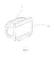
- FIG. 3 is an assembled view of the power charging socket of FIG. 2 , wherein the baffle board of the power charging socket closes a panel of the power charging socket.
- FIG. 4 is another assembled view of the power charging socket of FIG. 2 , wherein the baffle board opens.
- FIG. 5 is a disassembled view of the power charging socket of FIG. 4 .
- FIG. 6 is same as FIG. 5 , but viewed from another view.
- the power charging socket 100 of the disclosure is inlaid in a supporting body 200 .
- the power charging socket 100 includes a power socket module. 10 , a USB charging module 20 , a panel 40 and a baffle board 50 .
- the power socket module 10 includes a power port 11 exposed out of the panel 40 .
- the USB charging module 20 includes a charging port 21 exposed out of the panel 40 .
- a wireless charging transmitter is located inside the baffle board 50 .
- One end of the baffle board 50 is rotatably connected with a bottom of the panel 40 , and another end of the baffle board 50 is detachably connected with the panel 40 .
- the baffle board 50 closes the panel 40 to cover the power port 11 and the charging port 21 .
- the baffle board 50 closes the panel 40 to cover the power port 11 and the charging port 21 , which effectively prevents children touching the power port 11 and the charging port 21 to get electrical shock.
- the other end of the baffle board 50 detaches from the panel 40 .
- the electronic device carries out battery charging as long as the electronic device is laid on the baffle board 50 , and a data cable is connected between the charging port 21 and the electronic device.
- the baffle board 50 is configured to support the electronic device to protect the electronic device from damaging.
- the electronic device If the electronic device has a wireless charging receiver, the electronic device carries out battery charging as long as the baffle board 50 opens, and the electronic device is laid on the baffle board 50 .
- the power charging socket 100 of the disclosure employs the USB charging module 20 to install on a standard power socket.
- the electronic devices are directly inserted into the power charging socket 100 to carry out battery charging without connection with a charger, which gets rid of trouble for the consumers to carry chargers.
- the power charging socket 100 of the disclosure employs a baffle plate 50 to be rotatably connected with the panel 40 of the power charging socket 100 , and configures the wireless charging transmitter inside the baffle plate 50 .
- the baffle plate 50 not only supports the electronic device requiring battery charging, but also if the electronic device has a wireless charging receiver, the electronic device carries out battery charging as long as the electronic device is laid on the baffle plate 50 . Therefore, the electronic device embedded the wireless charging receiver can carry out battery charging without the data cable, which results of great convenience for the consumers.
- the baffle plate 50 closes the panel 40 to cover the charging port 21 and the power port 11 , which prevents electric shock effectively, and improves the safety of the power charging socket 100 .
- the supporting body 200 is interior walls in a room. Alternatively, the supporting body 200 may be a desktop.
- the power port 11 is configured for connecting exterior power plugs, and may be in the form of insertion holes in any shape or electrical connectors.
- the USB charging module 20 is configured for directly carrying out battery charging for the electronic device, and is equivalent to the charger corresponding to the electronic device.
- the charging port 21 is a USB interface.
- the electronic device carries out battery charging as long as a USB date cable is connected between the charging port 21 and the electronic device. If the electronic device with the wireless charging receiver, the electronic device carries out battery charging as long as the electronic device is laid on the baffle board 50 of the power charging socket 100 .
- the size of the power charging socket 100 of the disclosure is same as that of the standard power socket inlaid in the interior wall in the room. So that, the power charging socket 100 of the disclosure can be mounted in the interior wall when the room is decorated.
- the panel 40 with the rotably baffle board 50 instead of a panel of the existing standard power socket.
- the baffle board 50 is rotatably connected with the bottom of the panel 40 by hinges.
- the baffle board 50 is rotatably connected with the bottom of the panel 40 by way of engagement of shafts and shaft holes.
- the power charging socket 100 further includes a frame 30 and a housing 60 inlaid in the supporting body 200 .
- the power socket module 10 and the USB charging module 20 are positioned at the frame 30 . Ends of the power socket module 10 and the USB charging module 20 far away the frame 30 extend into the housing 60 .
- the frame 30 covers an open end of the housing 60 .
- the panel 40 is inlaid in the supporting body 200 , and fixed with the frame 30 .
- the frame 30 includes a first baseboard 31 defining a first positioning hole 33 , and a first rim 32 perpendicularly extending from edges of the first baseboard 31 .
- the power socket module 10 and the USB charging module 20 are positioned at the first positioning hole 33 , and the first rim 32 inserts into the panel 40 to fix with the panel 40 .
- the panel 40 includes a second baseboard 41 defining a second positioning hole 43 , and a second rim 42 perpendicularly extending from edges of the second baseboard 41 .
- the second rim 42 encapsulates the first rim 32 of the frame 30 , and the power port 11 and the charging port 21 pass through the second positioning hole 43 to expose out of the panel 40 .
- the first baseboard 31 defines a plurality of latching slots 35
- the second baseboard 41 includes a plurality of hooks 44 corresponding to the plurality of latching slots 35 .
- the plurality of hooks 44 latch into the plurality of latching slots 35 , respectively, to fix the panel 40 with the frame 30 .
- the frame 30 includes a sub-frame 34 extending from edges of the first positioning hole 33 and toward the panel 40 .
- the power socket module 10 and the USB charging module 20 are fixed in the sub-frame 34 .
- the baffle board 50 In use, when the electronic device requires battery charging, the baffle board 50 is opened, and the electronic device is laid on the baffle board 50 . One end of the data cable is inserted into a charging port of the electronic device, and another end of the data cable is inserted into the charging port 21 of the USB charging module 20 of the power charging socket 100 . If the electronic device has the wireless charging receiver, the electronic device carries out battery charging as long as the electronic device is laid on the baffle board 50 . When the electronic device finishes battery charging, the baffle board 50 closes to cover the panel 40 .
Landscapes
- Engineering & Computer Science (AREA)
- Power Engineering (AREA)
- Architecture (AREA)
- Civil Engineering (AREA)
- Structural Engineering (AREA)
- Charge And Discharge Circuits For Batteries Or The Like (AREA)
Abstract
Description
Claims (8)
Priority Applications (1)
| Application Number | Priority Date | Filing Date | Title |
|---|---|---|---|
| US14/159,463 US9252610B2 (en) | 2014-01-21 | 2014-01-21 | Power charging socket |
Applications Claiming Priority (1)
| Application Number | Priority Date | Filing Date | Title |
|---|---|---|---|
| US14/159,463 US9252610B2 (en) | 2014-01-21 | 2014-01-21 | Power charging socket |
Publications (2)
| Publication Number | Publication Date |
|---|---|
| US20150207350A1 US20150207350A1 (en) | 2015-07-23 |
| US9252610B2 true US9252610B2 (en) | 2016-02-02 |
Family
ID=53545670
Family Applications (1)
| Application Number | Title | Priority Date | Filing Date |
|---|---|---|---|
| US14/159,463 Expired - Fee Related US9252610B2 (en) | 2014-01-21 | 2014-01-21 | Power charging socket |
Country Status (1)
| Country | Link |
|---|---|
| US (1) | US9252610B2 (en) |
Cited By (10)
| Publication number | Priority date | Publication date | Assignee | Title |
|---|---|---|---|---|
| USD811348S1 (en) * | 2016-12-20 | 2018-02-27 | Molex, Llc | Connector housing |
| USD820218S1 (en) | 2016-12-20 | 2018-06-12 | Molex, Llc | Connector housing |
| US20180219322A1 (en) * | 2014-07-29 | 2018-08-02 | Gerald Beranek | Covering |
| US10141700B2 (en) * | 2014-05-07 | 2018-11-27 | Hubbell Incorporated | Integrated modular multimedia system in wall-box format |
| USD838250S1 (en) * | 2017-05-03 | 2019-01-15 | Donald Smith | Flush ring spacer design for electrical receptacles |
| US10340722B2 (en) | 2015-06-05 | 2019-07-02 | Pass & Seymour, Inc. | Electrical wiring assembly |
| US10720727B1 (en) | 2016-07-27 | 2020-07-21 | Ibo Partners, Llc | Outlet cover assembly with electrical connection |
| USD895556S1 (en) * | 2017-03-10 | 2020-09-08 | Norman R. Byrne | Low voltage outlet |
| US10886717B2 (en) * | 2018-09-25 | 2021-01-05 | Bryan Daab | Electrical outlet incorporating a charger for electronics devices and a cover plate therefor |
| US10951052B2 (en) | 2015-06-05 | 2021-03-16 | Pass & Seymour, Inc. | Wireless charger |
Families Citing this family (19)
| Publication number | Priority date | Publication date | Assignee | Title |
|---|---|---|---|---|
| US10027149B2 (en) | 2014-06-29 | 2018-07-17 | William J. Warren | Electrical charging device chassis and cases |
| US10063088B2 (en) | 2014-06-29 | 2018-08-28 | William J. Warren | Computing device inductive charging cases and methods of use |
| US10153649B2 (en) | 2014-06-29 | 2018-12-11 | William J. Warren | Computing device charging cases and methods of use |
| US9620911B2 (en) * | 2014-06-29 | 2017-04-11 | William J. Warren | Electrical charging devices and assemblies |
| US10219599B2 (en) | 2015-11-06 | 2019-03-05 | JRSK, Inc. | Hard-shell luggage systems |
| US10595608B2 (en) | 2015-11-06 | 2020-03-24 | JRSK, Inc. | Luggage system employing a telescopically-extendable handle and battery power supply assembly equipped with a semi-automatic battery power module ejection mechanism |
| US10608384B2 (en) | 2017-02-27 | 2020-03-31 | William J. Warren | Electrical charging devices with bar stabilizers and assemblies |
| US10608449B2 (en) | 2017-02-27 | 2020-03-31 | William J. Warren | Electrical charging devices with translating stabilizers |
| US9997882B1 (en) | 2017-02-27 | 2018-06-12 | William J. Warren | Electrical charging devices and assemblies |
| US10177584B2 (en) | 2017-02-27 | 2019-01-08 | William J. Warren | Electrical charging devices and assemblies |
| WO2018187304A1 (en) * | 2017-04-04 | 2018-10-11 | Hubbell Incorporated | Receptacle inductive charging devices |
| USD886733S1 (en) | 2017-04-11 | 2020-06-09 | William J. Warren | Charger |
| US10355501B2 (en) | 2017-10-11 | 2019-07-16 | William J. Warren | Electrical charging devices with resilient actuation |
| GB2573003A (en) * | 2018-04-19 | 2019-10-23 | Christopher Hoyle Dominic | An electrical socket device |
| USD979939S1 (en) | 2019-08-21 | 2023-03-07 | JRSK, Inc. | Luggage |
| USD965974S1 (en) | 2019-08-21 | 2022-10-11 | JRSK, Inc. | Luggage |
| USD979938S1 (en) | 2019-08-21 | 2023-03-07 | JRSK, Inc. | Luggage |
| WO2021047257A1 (en) * | 2019-09-10 | 2021-03-18 | 东莞市趣电智能科技有限公司 | Closed charging pile |
| US11509130B2 (en) * | 2021-02-10 | 2022-11-22 | Qualcomm Incorporated | Disconnection arc prevention in cable-supplied power connection |
Citations (11)
| Publication number | Priority date | Publication date | Assignee | Title |
|---|---|---|---|---|
| US20100029109A1 (en) * | 2007-06-08 | 2010-02-04 | Chung Man Lam | Multifunctional Wall Socket |
| US20110287665A1 (en) * | 2004-10-01 | 2011-11-24 | Tseng-Lu Chien | Universal module has USB-unit(s) or/and Outlet-unit(s) for variety of electric or digital data device(s) |
| US20120292991A1 (en) * | 2011-05-16 | 2012-11-22 | Cooper Technologies Company | Combination GFCI/AFCI Receptacle with Class 2 Power Units |
| US20130207472A1 (en) * | 2012-02-13 | 2013-08-15 | Kuo-Ching Chiang | Extension USB Socket |
| US20130257363A1 (en) * | 2012-03-30 | 2013-10-03 | Toyota Motor Engineering & Manufacturing North America, Inc. | Console assembly with charging state indicator |
| US20130267116A1 (en) * | 2012-04-06 | 2013-10-10 | Kyohaya Technology Ltd. | Wall outlet type usb hub with independent charging function |
| US20150129722A1 (en) * | 2013-11-05 | 2015-05-14 | Philip Green | Outlet cover wall dock |
| US20150145272A1 (en) * | 2013-11-22 | 2015-05-28 | Toyota Motor Engineering & Manufacturing North America, Inc. | Rear pass through power outlet |
| US20150167957A1 (en) * | 2013-12-13 | 2015-06-18 | Tseng-Lu Chien | The LED Light Has Multiple Functions |
| US20150263447A1 (en) * | 2014-03-14 | 2015-09-17 | Sheng-Hsin Liao | Wall socket having connecting module and wall switch having connecting module |
| US20150320209A1 (en) * | 2014-05-09 | 2015-11-12 | MirrorCache LLC | Secure access mirror |
-
2014
- 2014-01-21 US US14/159,463 patent/US9252610B2/en not_active Expired - Fee Related
Patent Citations (11)
| Publication number | Priority date | Publication date | Assignee | Title |
|---|---|---|---|---|
| US20110287665A1 (en) * | 2004-10-01 | 2011-11-24 | Tseng-Lu Chien | Universal module has USB-unit(s) or/and Outlet-unit(s) for variety of electric or digital data device(s) |
| US20100029109A1 (en) * | 2007-06-08 | 2010-02-04 | Chung Man Lam | Multifunctional Wall Socket |
| US20120292991A1 (en) * | 2011-05-16 | 2012-11-22 | Cooper Technologies Company | Combination GFCI/AFCI Receptacle with Class 2 Power Units |
| US20130207472A1 (en) * | 2012-02-13 | 2013-08-15 | Kuo-Ching Chiang | Extension USB Socket |
| US20130257363A1 (en) * | 2012-03-30 | 2013-10-03 | Toyota Motor Engineering & Manufacturing North America, Inc. | Console assembly with charging state indicator |
| US20130267116A1 (en) * | 2012-04-06 | 2013-10-10 | Kyohaya Technology Ltd. | Wall outlet type usb hub with independent charging function |
| US20150129722A1 (en) * | 2013-11-05 | 2015-05-14 | Philip Green | Outlet cover wall dock |
| US20150145272A1 (en) * | 2013-11-22 | 2015-05-28 | Toyota Motor Engineering & Manufacturing North America, Inc. | Rear pass through power outlet |
| US20150167957A1 (en) * | 2013-12-13 | 2015-06-18 | Tseng-Lu Chien | The LED Light Has Multiple Functions |
| US20150263447A1 (en) * | 2014-03-14 | 2015-09-17 | Sheng-Hsin Liao | Wall socket having connecting module and wall switch having connecting module |
| US20150320209A1 (en) * | 2014-05-09 | 2015-11-12 | MirrorCache LLC | Secure access mirror |
Cited By (12)
| Publication number | Priority date | Publication date | Assignee | Title |
|---|---|---|---|---|
| US10141700B2 (en) * | 2014-05-07 | 2018-11-27 | Hubbell Incorporated | Integrated modular multimedia system in wall-box format |
| US20180219322A1 (en) * | 2014-07-29 | 2018-08-02 | Gerald Beranek | Covering |
| US11018448B2 (en) * | 2014-07-29 | 2021-05-25 | Gerald Beranek | Covering |
| US10340722B2 (en) | 2015-06-05 | 2019-07-02 | Pass & Seymour, Inc. | Electrical wiring assembly |
| US10951052B2 (en) | 2015-06-05 | 2021-03-16 | Pass & Seymour, Inc. | Wireless charger |
| US10720727B1 (en) | 2016-07-27 | 2020-07-21 | Ibo Partners, Llc | Outlet cover assembly with electrical connection |
| US11011867B1 (en) | 2016-07-27 | 2021-05-18 | Ibo Partners, Llc | Outlet cover assembly with electrical connection |
| USD811348S1 (en) * | 2016-12-20 | 2018-02-27 | Molex, Llc | Connector housing |
| USD820218S1 (en) | 2016-12-20 | 2018-06-12 | Molex, Llc | Connector housing |
| USD895556S1 (en) * | 2017-03-10 | 2020-09-08 | Norman R. Byrne | Low voltage outlet |
| USD838250S1 (en) * | 2017-05-03 | 2019-01-15 | Donald Smith | Flush ring spacer design for electrical receptacles |
| US10886717B2 (en) * | 2018-09-25 | 2021-01-05 | Bryan Daab | Electrical outlet incorporating a charger for electronics devices and a cover plate therefor |
Also Published As
| Publication number | Publication date |
|---|---|
| US20150207350A1 (en) | 2015-07-23 |
Similar Documents
| Publication | Publication Date | Title |
|---|---|---|
| US9252610B2 (en) | Power charging socket | |
| US9544005B2 (en) | Adaptable mobile phone case with battery and charger | |
| US9072172B2 (en) | Auxiliary device for mobile electronic apparatus | |
| CN106331930A (en) | Charging box of wireless headset and wireless headset adapting to charging box | |
| US20080125188A1 (en) | Cellular phone case capable of charging battery by solar energy | |
| US8680809B2 (en) | Battery charger | |
| US20160013680A1 (en) | Wireless charging battery and corresponding electric device | |
| US20160294133A1 (en) | Plug with integrated self-replicated socket | |
| US9356641B2 (en) | Protective case and electronic device using same | |
| US20110223806A1 (en) | vehicle used power charge assembly for electronic devices | |
| KR101668461B1 (en) | A Device for interface of an electronic equipment | |
| US20130251171A1 (en) | Portable charger for a blue-tooth headset | |
| CN203690630U (en) | Charging socket | |
| CN208316360U (en) | mobile terminal charging device | |
| US20180175654A1 (en) | Portable Speaker Charging Structure | |
| CN102082379B (en) | Terminal rotation device and USB module equipped with the terminal rotation device | |
| WO2016145828A1 (en) | Mobile battery | |
| CN203850862U (en) | A portable charger | |
| CN106617570B (en) | A kind of transit switch and the luggage for having transit switch | |
| CN205178205U (en) | Intelligent power socket | |
| US20120002579A1 (en) | Network adapter with wireless network access function | |
| KR200473420Y1 (en) | A housing for USB charging socket outlet | |
| CN206349770U (en) | A kind of charging device and intelligent charge equipment | |
| CN216529700U (en) | Wireless charging assembly with data line storage function | |
| CN205336347U (en) | Rechargeable cell -phone shell |
Legal Events
| Date | Code | Title | Description |
|---|---|---|---|
| ZAAA | Notice of allowance and fees due |
Free format text: ORIGINAL CODE: NOA |
|
| ZAAB | Notice of allowance mailed |
Free format text: ORIGINAL CODE: MN/=. |
|
| AS | Assignment |
Owner name: YOUHUA TECHNOLOGY (SHENZHEN) CO., LTD., CHINA Free format text: ASSIGNMENT OF ASSIGNORS INTEREST;ASSIGNORS:CHEN, SHIH CHUNG;CHEN, SHU-MU;REEL/FRAME:037365/0762 Effective date: 20151224 |
|
| STCF | Information on status: patent grant |
Free format text: PATENTED CASE |
|
| MAFP | Maintenance fee payment |
Free format text: PAYMENT OF MAINTENANCE FEE, 4TH YR, SMALL ENTITY (ORIGINAL EVENT CODE: M2551); ENTITY STATUS OF PATENT OWNER: SMALL ENTITY Year of fee payment: 4 |
|
| AS | Assignment |
Owner name: LINKCOM MANUFACTURING CO., LTD., CHINA Free format text: ASSIGNMENT OF ASSIGNORS INTEREST;ASSIGNOR:YOUHUA TECHNOLOGY (SHENZHEN) CO., LTD.;REEL/FRAME:062256/0485 Effective date: 20221222 |
|
| FEPP | Fee payment procedure |
Free format text: MAINTENANCE FEE REMINDER MAILED (ORIGINAL EVENT CODE: REM.); ENTITY STATUS OF PATENT OWNER: SMALL ENTITY |
|
| LAPS | Lapse for failure to pay maintenance fees |
Free format text: PATENT EXPIRED FOR FAILURE TO PAY MAINTENANCE FEES (ORIGINAL EVENT CODE: EXP.); ENTITY STATUS OF PATENT OWNER: SMALL ENTITY |
|
| STCH | Information on status: patent discontinuation |
Free format text: PATENT EXPIRED DUE TO NONPAYMENT OF MAINTENANCE FEES UNDER 37 CFR 1.362 |
|
| FP | Lapsed due to failure to pay maintenance fee |
Effective date: 20240202 |