US924924A - Tire-armor. - Google Patents
Tire-armor. Download PDFInfo
- Publication number
- US924924A US924924A US44862108A US1908448621A US924924A US 924924 A US924924 A US 924924A US 44862108 A US44862108 A US 44862108A US 1908448621 A US1908448621 A US 1908448621A US 924924 A US924924 A US 924924A
- Authority
- US
- United States
- Prior art keywords
- sections
- tire
- armor
- hooks
- rings
- Prior art date
- Legal status (The legal status is an assumption and is not a legal conclusion. Google has not performed a legal analysis and makes no representation as to the accuracy of the status listed.)
- Expired - Lifetime
Links
Images
Classifications
-
- B—PERFORMING OPERATIONS; TRANSPORTING
- B60—VEHICLES IN GENERAL
- B60C—VEHICLE TYRES; TYRE INFLATION; TYRE CHANGING; CONNECTING VALVES TO INFLATABLE ELASTIC BODIES IN GENERAL; DEVICES OR ARRANGEMENTS RELATED TO TYRES
- B60C27/00—Non-skid devices temporarily attachable to resilient tyres or resiliently-tyred wheels
- B60C27/06—Non-skid devices temporarily attachable to resilient tyres or resiliently-tyred wheels extending over the complete circumference of the tread, e.g. made of chains or cables
- B60C27/16—Non-skid devices temporarily attachable to resilient tyres or resiliently-tyred wheels extending over the complete circumference of the tread, e.g. made of chains or cables formed of close material, e.g. leather or synthetic mats
Definitions
- My invention relatesto certain new and useful improvements in tire armors especially adapted to be used in connection w1thpneumatic tires, the object being to provide an annular shield or armor consisting of a plurality of metallic sections, each section articulating with the next two sections, and held in place by a metallic ring on each side, and a leather or pliable belt on each inner side to rotect the rubber tire, so as to make 7 a comp ete circumferential shield or armor for the periphery and adjoining portion of the tire exposed.
- a still furtherobjectof my invention is to simple and cheap in construction, and one in which the sections are so connected together and held in position upon the tire that all danger of the sections becoming accidentally detached, is prevented.
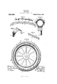
- FIG. 1 is a vertical section through a portion of my improved tire armor.
- Fig. 2 is a transverse sectlon through a wheel showing my improved armor in position thereon.
- Fig. 3 is a perspective view of one of the armor sections.
- Fig. 4 is a side elevation of a wheel showing my improved armor in position thereon, and
- Fig. 5 is a perspective view of a portion of the leather belt.
- each section consisting of a metallic saddle or clip A, curved to fit the periphery of the tire transversely, and reduced at itsen'ds, which are bent upwardly to form hooks or bearings a, (1, adapted to receive metallic rings b, b, as will be hereinafter described.
- a lug or spur c is formed at one end of each of the sections,-about midway between the hopks, and adjacent the other edge of the section in transverse alinement with the lug, a slot 01 is formed which is adapted to receive the lug of the adjacent section, when the sections are placed together, over a tire to form the armor.
- the metallic rings are formed of such size that they will fit 1 shugly within the hooks of all of the sections 0 t tions in their proper positions.
- the hooked en s of. the sections are forced under the loops of the belt, on each side, and the spurs of the sections are forced into the slots of the sections, so as to lock the sections in their proper position in respect to each other, and the metallic rings are then placed in position in the hooks of the sections which securely hold the sections, so that it is imossible for one of the same to become accidentally detached.
- the armor ted to the tire suificiently loose to allow agvery slow retrogressive movement of the armor circumferentially around the tire, so asto revent the tire from wearing unevenly, the movement be' ing produced by the form and manner of adjustmg the sections, and narrowing their ends.
- An armor for pneumatic tires com rising a plurality of overlap ing and inter ocking sections, curved to t over a tire, and having books at their ends, belts of. pliable material adapted to fit on the opposite sides of the tire, and rovided with a plurality of loops through w oh the ends of the sections projkect, and metallic rings engaging the 00 s of the section.
- An armor for pneumatic tires comprise armor, so as tosecurely hold the secin a plurality of overlapping and intertallicf rings e'ngagingfthe hooks of thesecloc g sections, curved to fit qver a tire, tions. 10 said sections having reduced ends and hooks In testimony whereof I aflix my signature on said ends, leather belts adapted to fit-on in presence of two witn.
Landscapes
- Engineering & Computer Science (AREA)
- Mechanical Engineering (AREA)
- Tires In General (AREA)
Description
- W. ONEIL.
TIRE ARMOR.
APPLICATION FILED AUG. 14, 1908.
924,924. Patented June 15,1909.
4 provide a tire armor which is exceedingly .amAT-IBE-ARMOR.
P TEN iW-i nmMo'Nn IL, or MILWAUKEE, wi'scoNsi Specification of Letters Patent.
Application filed August 14, 1908.
Pasta-d rue-15,1909.
Serial No. 448,621.
To all whom 'it may concern:
Be it .known' that I, VVILLIAM ONEIL, a citizen of the United States, residin at Milwaukee, in the county of Milwaukee and State of Wisconsin, have invented certain new and useful Improvements in Tire- Armors, of which the following is a specification.
My invention relatesto certain new and useful improvements in tire armors especially adapted to be used in connection w1thpneumatic tires, the object being to provide an annular shield or armor consisting of a plurality of metallic sections, each section articulating with the next two sections, and held in place by a metallic ring on each side, and a leather or pliable belt on each inner side to rotect the rubber tire, so as to make 7 a comp ete circumferential shield or armor for the periphery and adjoining portion of the tire exposed.
A still furtherobjectof my invention is to simple and cheap in construction, and one in which the sections are so connected together and held in position upon the tire that all danger of the sections becoming accidentally detached, is prevented.
With these objects in view, my invention consists. in the novel features of combination, and arrangement of parts, hereinafter fully described and pointed out in the claims. In the drawing forming a part of this specification: Figure 1 is a vertical section through a portion of my improved tire armor. Fig. 2 is a transverse sectlon through a wheel showing my improved armor in position thereon. Fig. 3 is a perspective view of one of the armor sections. Fig. 4 is a side elevation of a wheel showing my improved armor in position thereon, and Fig. 5 is a perspective view of a portion of the leather belt.
In carrying out my invention I employ a plurality of sections to form my armor, each section consisting of a metallic saddle or clip A, curved to fit the periphery of the tire transversely, and reduced at itsen'ds, which are bent upwardly to form hooks or bearings a, (1, adapted to receive metallic rings b, b, as will be hereinafter described. A lug or spur c, is formed at one end of each of the sections,-about midway between the hopks, and adjacent the other edge of the section in transverse alinement with the lug, a slot 01 is formed which is adapted to receive the lug of the adjacent section, when the sections are placed together, over a tire to form the armor.
In connection with the armor sections, I
use a pair of leather belts f, f which are provided with parallel slits forming loops e, e,
through which the ends of the. armor sec-3' tions are adapted to be inserted before the. metallic rings 1), b, are placed in position in the hooks oi the sections, and it will be Seen that b this arrangement the armor'sections are he d away from the tire a slight distance by the belts, which form protectors for-the sections, so as to prevent the tire from be? coming injured, and it will also be seen that the loops of the belt prevent the rings from moving upwardl out of the hooks of the sections, so that a danger-of the rings becoming accidentally detachedfi': by the sudden exertionyis prevented.
It is of course unders ood that the metallic rings are formed of such size that they will fit 1 shugly within the hooks of all of the sections 0 t tions in their proper positions.
In placing m improved armor on a tire, the hooked en s of. the sections are forced under the loops of the belt, on each side, and the spurs of the sections are forced into the slots of the sections, so as to lock the sections in their proper position in respect to each other, and the metallic rings are then placed in position in the hooks of the sections which securely hold the sections, so that it is imossible for one of the same to become accidentally detached.
The armor ted to the tire, suificiently loose to allow agvery slow retrogressive movement of the armor circumferentially around the tire, so asto revent the tire from wearing unevenly, the movement be' ing produced by the form and manner of adjustmg the sections, and narrowing their ends.
What I claim as m invention, and desire to secure by Letters atent is:
1. An armor for pneumatic tires com rising a plurality of overlap ing and inter ocking sections, curved to t over a tire, and having books at their ends, belts of. pliable material adapted to fit on the opposite sides of the tire, and rovided with a plurality of loops through w oh the ends of the sections projkect, and metallic rings engaging the 00 s of the section.
2. An armor for pneumatic tires comprise armor, so as tosecurely hold the secin a plurality of overlapping and intertallicf rings e'ngagingfthe hooks of thesecloc g sections, curved to fit qver a tire, tions. 10 said sections having reduced ends and hooks In testimony whereof I aflix my signature on said ends, leather belts adapted to fit-on in presence of two witn.
5 opfosite sides of the tire and each being pro- ONEIL. v V: ed with. a lurality of 'ai'rs of parallel Witnesses: ,7 slits forming oops throug which the re- MARGARET Frm'ron,
duced ends of the sections project, and me- ELBIE M.Ho'1 z.
Priority Applications (1)
| Application Number | Priority Date | Filing Date | Title |
|---|---|---|---|
| US44862108A US924924A (en) | 1908-08-14 | 1908-08-14 | Tire-armor. |
Applications Claiming Priority (1)
| Application Number | Priority Date | Filing Date | Title |
|---|---|---|---|
| US44862108A US924924A (en) | 1908-08-14 | 1908-08-14 | Tire-armor. |
Publications (1)
| Publication Number | Publication Date |
|---|---|
| US924924A true US924924A (en) | 1909-06-15 |
Family
ID=2993353
Family Applications (1)
| Application Number | Title | Priority Date | Filing Date |
|---|---|---|---|
| US44862108A Expired - Lifetime US924924A (en) | 1908-08-14 | 1908-08-14 | Tire-armor. |
Country Status (1)
| Country | Link |
|---|---|
| US (1) | US924924A (en) |
-
1908
- 1908-08-14 US US44862108A patent/US924924A/en not_active Expired - Lifetime
Similar Documents
| Publication | Publication Date | Title |
|---|---|---|
| US924924A (en) | Tire-armor. | |
| US1012909A (en) | Shaft-protector. | |
| US681151A (en) | Tire for vehicles. | |
| US1235080A (en) | Tire-tube protector. | |
| US887295A (en) | Automobile-tire. | |
| US1596735A (en) | Nonskid chain | |
| US804892A (en) | Protective tread for pneumatic tires. | |
| US911203A (en) | Tire-shield. | |
| US1042178A (en) | Tire. | |
| US938371A (en) | Detachable tread for automobile-tires. | |
| US929203A (en) | Tire-shield. | |
| US1042157A (en) | Tire-protector. | |
| US1228001A (en) | Tire casing or shoe. | |
| US777979A (en) | Pneumatic tire. | |
| US1146221A (en) | Antiskidding armor for tires. | |
| US1109972A (en) | Pneumatic tire. | |
| US509925A (en) | Tire-protector | |
| US937812A (en) | Tire-armor. | |
| US798195A (en) | Pneumatic-tire protector. | |
| US610622A (en) | chambers | |
| US879676A (en) | Tire of wheels. | |
| US1024458A (en) | Tire-protector. | |
| US1223776A (en) | Armored pneumatic tire. | |
| US964131A (en) | Shield for tires. | |
| US1352370A (en) | Vehicle-tire |