US9248454B2 - Device and method for recovering magnetic particles trapped on a magnetic plug - Google Patents
Device and method for recovering magnetic particles trapped on a magnetic plug Download PDFInfo
- Publication number
- US9248454B2 US9248454B2 US13/504,277 US201013504277A US9248454B2 US 9248454 B2 US9248454 B2 US 9248454B2 US 201013504277 A US201013504277 A US 201013504277A US 9248454 B2 US9248454 B2 US 9248454B2
- Authority
- US
- United States
- Prior art keywords
- enclosure
- magnetic
- particles
- opening
- magnetization
- Prior art date
- Legal status (The legal status is an assumption and is not a legal conclusion. Google has not performed a legal analysis and makes no representation as to the accuracy of the status listed.)
- Active, expires
Links
- 230000005291 magnetic effect Effects 0.000 title claims abstract description 54
- 239000006249 magnetic particle Substances 0.000 title claims abstract description 25
- 238000000034 method Methods 0.000 title claims description 17
- 239000002245 particle Substances 0.000 claims abstract description 51
- 230000005415 magnetization Effects 0.000 claims abstract description 32
- 239000007788 liquid Substances 0.000 claims abstract description 18
- 238000002347 injection Methods 0.000 claims abstract description 15
- 239000007924 injection Substances 0.000 claims abstract description 15
- 238000011084 recovery Methods 0.000 claims abstract description 12
- 239000012530 fluid Substances 0.000 claims abstract description 10
- 230000000717 retained effect Effects 0.000 claims abstract description 8
- 238000007789 sealing Methods 0.000 claims description 5
- 238000005192 partition Methods 0.000 claims 1
- 238000004458 analytical method Methods 0.000 description 6
- 239000004744 fabric Substances 0.000 description 4
- 230000005294 ferromagnetic effect Effects 0.000 description 3
- 239000000243 solution Substances 0.000 description 3
- XEEYBQQBJWHFJM-UHFFFAOYSA-N Iron Chemical compound [Fe] XEEYBQQBJWHFJM-UHFFFAOYSA-N 0.000 description 2
- 239000000853 adhesive Substances 0.000 description 2
- 230000001070 adhesive effect Effects 0.000 description 2
- 239000000463 material Substances 0.000 description 2
- 239000002184 metal Substances 0.000 description 2
- 229910052751 metal Inorganic materials 0.000 description 2
- 229920003023 plastic Polymers 0.000 description 2
- RYGMFSIKBFXOCR-UHFFFAOYSA-N Copper Chemical compound [Cu] RYGMFSIKBFXOCR-UHFFFAOYSA-N 0.000 description 1
- 230000002159 abnormal effect Effects 0.000 description 1
- 239000002390 adhesive tape Substances 0.000 description 1
- 230000015572 biosynthetic process Effects 0.000 description 1
- 239000002826 coolant Substances 0.000 description 1
- 238000001816 cooling Methods 0.000 description 1
- 229910052802 copper Inorganic materials 0.000 description 1
- 239000010949 copper Substances 0.000 description 1
- 238000004090 dissolution Methods 0.000 description 1
- 230000000694 effects Effects 0.000 description 1
- 238000002149 energy-dispersive X-ray emission spectroscopy Methods 0.000 description 1
- 238000001914 filtration Methods 0.000 description 1
- 239000000446 fuel Substances 0.000 description 1
- 239000011521 glass Substances 0.000 description 1
- 229910052742 iron Inorganic materials 0.000 description 1
- 238000005461 lubrication Methods 0.000 description 1
- 239000013528 metallic particle Substances 0.000 description 1
- 244000045947 parasite Species 0.000 description 1
- 230000001902 propagating effect Effects 0.000 description 1
- 230000000630 rising effect Effects 0.000 description 1
- 238000004626 scanning electron microscopy Methods 0.000 description 1
- 230000035939 shock Effects 0.000 description 1
- 239000002904 solvent Substances 0.000 description 1
Images


Classifications
-
- B—PERFORMING OPERATIONS; TRANSPORTING
- B03—SEPARATION OF SOLID MATERIALS USING LIQUIDS OR USING PNEUMATIC TABLES OR JIGS; MAGNETIC OR ELECTROSTATIC SEPARATION OF SOLID MATERIALS FROM SOLID MATERIALS OR FLUIDS; SEPARATION BY HIGH-VOLTAGE ELECTRIC FIELDS
- B03C—MAGNETIC OR ELECTROSTATIC SEPARATION OF SOLID MATERIALS FROM SOLID MATERIALS OR FLUIDS; SEPARATION BY HIGH-VOLTAGE ELECTRIC FIELDS
- B03C1/00—Magnetic separation
- B03C1/02—Magnetic separation acting directly on the substance being separated
- B03C1/28—Magnetic plugs and dipsticks
- B03C1/284—Magnetic plugs and dipsticks with associated cleaning means, e.g. retractable non-magnetic sleeve
-
- B—PERFORMING OPERATIONS; TRANSPORTING
- B03—SEPARATION OF SOLID MATERIALS USING LIQUIDS OR USING PNEUMATIC TABLES OR JIGS; MAGNETIC OR ELECTROSTATIC SEPARATION OF SOLID MATERIALS FROM SOLID MATERIALS OR FLUIDS; SEPARATION BY HIGH-VOLTAGE ELECTRIC FIELDS
- B03C—MAGNETIC OR ELECTROSTATIC SEPARATION OF SOLID MATERIALS FROM SOLID MATERIALS OR FLUIDS; SEPARATION BY HIGH-VOLTAGE ELECTRIC FIELDS
- B03C1/00—Magnetic separation
- B03C1/02—Magnetic separation acting directly on the substance being separated
- B03C1/025—High gradient magnetic separators
- B03C1/031—Component parts; Auxiliary operations
- B03C1/032—Matrix cleaning systems
-
- B—PERFORMING OPERATIONS; TRANSPORTING
- B03—SEPARATION OF SOLID MATERIALS USING LIQUIDS OR USING PNEUMATIC TABLES OR JIGS; MAGNETIC OR ELECTROSTATIC SEPARATION OF SOLID MATERIALS FROM SOLID MATERIALS OR FLUIDS; SEPARATION BY HIGH-VOLTAGE ELECTRIC FIELDS
- B03C—MAGNETIC OR ELECTROSTATIC SEPARATION OF SOLID MATERIALS FROM SOLID MATERIALS OR FLUIDS; SEPARATION BY HIGH-VOLTAGE ELECTRIC FIELDS
- B03C1/00—Magnetic separation
- B03C1/02—Magnetic separation acting directly on the substance being separated
- B03C1/28—Magnetic plugs and dipsticks
- B03C1/286—Magnetic plugs and dipsticks disposed at the inner circumference of a recipient, e.g. magnetic drain bolt
Definitions
- the invention relates to a device and method for recovering magnetic particles trapped on a magnetic plug intended to retain, by means of a magnet, the magnetic particles in a liquid resulting from the wear of parts, such as for example rotating parts disposed in an equipment case or aircraft engine.
- a magnetic plug is placed in a liquid circuit (typically oil, liquid coolant or fuel) inside a case containing the moving parts, such as gear wheels or bearings, that stand in said liquid.
- a liquid circuit typically oil, liquid coolant or fuel
- the function of the liquid circuit is to enable the lubrication and/or cooling of moving parts (typically rotating parts). It turns out that the moving parts are caused to wear away throughout their lives, for example due to the friction resulting from the contact between two toothed wheels or bearings, or rather due to the shocks or intense friction between rotating parts due to intense and abnormal vibrations propagating through the case. Whatever the cause, the wear of parts leads to the formation of particles that detach from the parts and are driven by the liquid in the liquid circuit. Insofar as the rotating parts are generally metallic, the particles resulting from the wear of parts are conductive and are generally present in the form of filings. Furthermore, the parts are most often made from a ferromagnetic type metal such as iron, i.e., a metal that is capable of being attracted by a magnetic element such as a magnet.
- a ferromagnetic type metal such as iron
- a magnetic plug 1 comprises at one end a head or support 2 and a permanent magnet formed by a magnetic bar 3 immersed in a liquid circuit, said magnetic bar 3 attracting metallic particles 4 when the liquid circulates.
- the operators on site must then periodically verify the condition of these magnetic plugs, remove the particles trapped on the magnetic bar and analyze these particles, for example by analyses of the SEM Scanning Electron Microscopy and EDS Energy Dispersive Spectroscopy type. From these analyses, it is possible to identify the nature and geometry of the removed particles; depending on the removal site of the plug, one may then limit the element or elements affected by wear and take measures that will guarantee the integrity of the machine and safety of the flight. It will be noted that the magnetic plugs are most often coupled with filters, the latter used to trap non-ferromagnetic particles.
- a first technique consists of using adhesive tape that the operator puts in contact with the magnetic bar of the plug. Such a solution is not entirely satisfactory insofar as the particles remain stuck on the adhesive and are difficult to extract (by dissolution) for analysis. Therefore it remains a residue of particles that cannot be used in the analysis and leads to a loss of data.
- the adhesive may generate surface pollution of the particles that is likely to distort the material analysis results.
- a second technique consists of using a cloth to remove the particles on the magnetic bar.
- a third technique may consist of directly removing the particles on the bar by using a magnet that is more powerful than the magnet of the magnetic bar.
- the goal of the invention is to remedy the aforementioned disadvantages.
- the present invention aims to provide a device enabling the rapid, reliable and complete recovery of magnetic particles trapped on a magnetic plug.
- the invention applies to a device for recovering magnetic particles trapped on a magnetic plug, said magnetic plug comprising a supporting end and a magnetized element intended to retain the magnetic particles driven by a liquid resulting from the wear of parts with which said liquid has been in contact, said recovery device comprising:
- an injection of pressurized gas (preferentially filtered and de-oiled compressed air, injected for example at 6 bar) is utilized via at least one nozzle.
- the flow of gas will enable the magnetic particles found on the magnetic plug to be detached and will enable these particles to be sent to the bottom of the device enclosure.
- the presence of magnetization means preferentially arranged near the bottom and outside of the enclosure will enable these particles to be trapped (i.e., the particles may not rise again since they are trapped by the magnetization means). Therefore the device according to the invention is a tool for operators enabling all magnetic particles to be reliably recovered, these magnetic particles being disconnected from the magnetic plug under the effect of a jet of air when the plug is placed in the tool enclosure.
- the device according to the invention may present one or more of the additional characteristics below, considered individually or according to all technically feasible combinations:
- Another object of the invention is a method for recovering magnetic particles trapped on a magnetic plug by using a device according to the invention, said method comprising the following steps:
- the step of recovering the particles comprises the following steps:
- FIG. 1 schematically represents a magnetic plug
- FIG. 2 schematically represents a device for recovering particles according to the invention
- FIGS. 3 to 7 illustrate the different steps of a method for recovering particles according to the invention
- FIG. 8 represents the sequence of steps illustrated in FIGS. 3 to 7 .
- FIG. 1 has already been described with reference to the prior art.
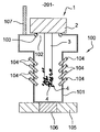
- FIG. 2 schematically represents a device 100 for recovering magnetic particles according to the invention.
- the device 100 according to the invention comprises:
- Each of the nozzles 104 is tilted by an angle of 45° with relation to the vertical axis OO′.
- Enclosure 101 may be made of a transparent plastic material.
- FIG. 8 represents the sequence of steps 201 to 205 of method 200 . It will be noted that these steps 201 to 205 will preferentially be implemented on site by an operator.
- the magnetic plug 1 After having been recovered by the operator for analyzing the trapped particles 4 , is placed in device 100 . More precisely, the magnetic bar 3 (on which the magnetic particles 4 are retained) is inserted in enclosure 101 and the supporting end 2 (or head) of the plug 1 blocks opening 102 . Opening 102 of device 1 thus must be sized so that its diameter is less than the diameter of the head 2 of plug 1 .
- the O-ring 103 ensures the sealing between the supporting end 2 and the opening 102 .
- filtered and de-oiled (to prevent any pollution of particles 4 ) compressed air is injected for some seconds via nozzles 104 inside enclosure 101 .
- the 45° tilt with relation to the vertical axis of nozzles 104 enables the jet of compressed air to be directed toward the end of the magnetic bar 3 on which the particles 4 are retained. All of the particles 4 found on bar 3 are consequently urged toward the bottom of the enclosure 101 and are trapped by magnet 106 that is sufficiently powerful to retain them at the bottom of the enclosure 101 and prevent them from rising back up toward the top of the enclosure.
- vent pipe 107 Insofar as an injection of compressed air is carried out within the enclosure 101 , a vent outlet is ensured by vent pipe 107 to prevent excess pressure.
- a magnet 106 presenting a magnetization (typically between 50 and 100 A/m) that is more powerful than that of the permanent magnet of the plug (generally between 25 and 30 A/m) will be chosen.
- the height of the enclosure 101 is adjusted so that the distance d separating the magnet 106 from the end of the magnetic bar 3 is between 2 and 5 cm: This distance d is sufficient so that the magnetization of the magnet 106 does not disrupt the magnetization of bar 3 that must remain substantially constant for a subsequent use.
- the magnetic plug 1 is extracted from device 100 according to the invention and then the magnet 106 is removed from support 105 (it is recalled that magnet 106 is assembled removably on support 105 ), the particles 4 are still located at the bottom of enclosure 101 .
- Step 204 illustrated in FIG. 6 will consist of recovering the particles 4 at the bottom of receptacle 101 .
- a copper cylinder 112 for example, sliding in a glass tube 111 with a magnet 110 at its lower end, is used.
- the particles 4 are magnetized by magnet 110 .
- the particles 4 are then recovered in a plastic pouch 113 by sliding the cylinder 112 in tube 111 upward (in the direction of the arrow); The act of raising the cylinder 112 suppresses the magnetic field exerted by magnet 110 on the particles 4 .
- the pouch 113 may then be sent by the operator to a laboratory for analyzing the particles 4 .
- the step of recovering particles at the bottom of the enclosure of the device according to the invention was described in the context of the use of a cylinder sliding in a tube. It is also perfectly possible to recover particles by turning the device according to the invention upside down in order to directly transfer the particles (that are no longer trapped by the previously removed magnet 106 ) into a pouch.
- the device was described more specifically with a removable magnet 106 .
- a non-removable electromagnet may also be used, whose magnetization will be controlled depending on whether one wishes or does not wish to maintain the trapped particles.
- the device preferentially comprises a plurality of nozzles distributed around the enclosure, one may also consider the use of only a single injection nozzle by rotating the plug inside the device according to the invention so that the jet of compressed air reaches the entire surface of the bar on which the particles are trapped.
- the device according to the invention finds a particularly interesting application in a use with magnetic plugs utilized on all machines for which the ability to detect wear is important, particularly on aeronautical turbine engines. On these machines, the utilization of several magnetic plugs on various oil systems may enable a part presenting the start of wear to be rapidly located.
Landscapes
- Sampling And Sample Adjustment (AREA)
- Physical Or Chemical Processes And Apparatus (AREA)
- Soft Magnetic Materials (AREA)
- Water Treatment By Electricity Or Magnetism (AREA)
- Magnetic Resonance Imaging Apparatus (AREA)
Abstract
Description
-
- magnetization means;
- an enclosure integrating:
- an opening, said enclosure being capable of receiving said magnetic plug via said opening such that said magnetized element is housed inside said enclosure and said supporting end is situated outside said enclosure, said opening being sized so that said supporting end blocks said opening;
- at least one injection nozzle capable of injecting a gaseous fluid inside said enclosure, said nozzle being oriented such that the flow of gaseous liquid expels the magnetic particles retained on the magnetized element toward the bottom of said enclosure, said magnetization means being arranged so as to trap, by means of magnetization, said particles urged toward the bottom of said enclosure.
-
- the device according to the invention comprises a plurality of injection nozzles assembled on said enclosure;
- said magnetized element of said magnetic plug is a magnetic bar; said enclosure is sized to receive said magnetic bar inside said enclosure and said nozzles are disposed laterally on said enclosure so that they are situated on both sides of said bar when the latter is in position inside said enclosure;
- each of said nozzles is tilted 45° with relation to the axis of the bar when the latter is in position inside said enclosure;
- said magnetization means are disposed outside said enclosure near the bottom of said enclosure;
- said magnetization means are removably assembled on the outer face of the bottom of said enclosure;
- said magnetization means are arranged so as to be situated at a distance of between 2 and 5 cm from said magnetized element when the latter is inside said enclosure;
- the device according to the invention comprises sealing means such as an O-ring capable of ensuring sealing between said supporting end and said opening when said supporting end blocks said opening.
-
- placing the magnetic plug in the recovery device via the enclosure opening such that the magnetized element of the plug retaining the magnetic particles is housed inside the enclosure and the supporting end of the plug is situated outside the enclosure so as to block the enclosure opening;
- injecting compressed air, preferentially filtered via the injection nozzle or nozzles so that the particles retained on the magnetic element are evacuated toward the bottom of the enclosure;
- trapping the evacuated particles toward the bottom of the enclosure by said magnetization means;
- recovering the particles trapped by said magnetization means.
-
- removal of the magnetic plug and magnetization means removably assembled under the bottom of the enclosure;
- recovery of the particles by using a magnetized bar assembled slidingly in a tube.
-
- a T-shaped
enclosure 101 with anopening 102 on its upper part and a substantially cylindrical receptacle 108 of vertical axis OO′; - sealing means 103 in the form of an O-ring disposed around the
opening 102; - a plurality of
injection nozzles 104 traversing the lateral parts of theenclosure 101; - a
support 105 arranged in contact with the outer surface of the bottom ofenclosure 101; - a
cylindrical magnet 106 removably assembled insupport 105; - a
vent pipe 107.
- a T-shaped
Claims (18)
Applications Claiming Priority (3)
| Application Number | Priority Date | Filing Date | Title |
|---|---|---|---|
| FR0957682A FR2951961B1 (en) | 2009-10-30 | 2009-10-30 | DEVICE AND METHOD FOR RECOVERING MAGNETIC PARTICLES SPILLED ON A MAGNETIC CAP |
| FR0957682 | 2009-10-30 | ||
| PCT/EP2010/066000 WO2011051192A1 (en) | 2009-10-30 | 2010-10-22 | Device and method for recovering magnetic particles trapped on a magnetic plug |
Publications (2)
| Publication Number | Publication Date |
|---|---|
| US20120204910A1 US20120204910A1 (en) | 2012-08-16 |
| US9248454B2 true US9248454B2 (en) | 2016-02-02 |
Family
ID=42224410
Family Applications (1)
| Application Number | Title | Priority Date | Filing Date |
|---|---|---|---|
| US13/504,277 Active 2032-11-03 US9248454B2 (en) | 2009-10-30 | 2010-10-22 | Device and method for recovering magnetic particles trapped on a magnetic plug |
Country Status (9)
| Country | Link |
|---|---|
| US (1) | US9248454B2 (en) |
| EP (1) | EP2493623B1 (en) |
| CN (1) | CN102596416B (en) |
| BR (1) | BR112012010100B1 (en) |
| CA (1) | CA2778856C (en) |
| ES (1) | ES2726428T3 (en) |
| FR (1) | FR2951961B1 (en) |
| RU (1) | RU2541685C2 (en) |
| WO (1) | WO2011051192A1 (en) |
Cited By (1)
| Publication number | Priority date | Publication date | Assignee | Title |
|---|---|---|---|---|
| US20220384075A1 (en) * | 2021-05-25 | 2022-12-01 | Victor Manuel Flores | Magnetic plugs for electrical containment enclosures |
Families Citing this family (9)
| Publication number | Priority date | Publication date | Assignee | Title |
|---|---|---|---|---|
| FR2957823B1 (en) * | 2010-03-29 | 2015-02-27 | Snecma | DEVICE AND METHOD FOR RECOVERING MAGNETIC PARTICLES SPILLED ON A MAGNETIC CAP |
| DE102014019526B4 (en) * | 2014-12-23 | 2016-10-27 | Testo Ag | Examination procedure, disk-shaped sample carrier and use of a sample carrier |
| CN111226116B (en) * | 2017-06-19 | 2024-05-03 | 微球实验公司 | Combined separation |
| CN112547618B (en) * | 2020-11-11 | 2021-12-17 | 东阳(吴江)汽车部件有限公司 | A device for cleaning mechanical parts |
| RU2771346C1 (en) * | 2021-01-29 | 2022-04-29 | Болтенков Евгений Владимирович | Magneto-gravity separator |
| RU206328U1 (en) * | 2021-01-29 | 2021-09-06 | Болтенков Евгений Владимирович | MAGNETOGRAVITATION SEPARATOR |
| CN114130736B (en) * | 2021-11-09 | 2022-11-11 | 武汉惠强新能源材料科技有限公司 | Device for automatically separating magnetic substances |
| TWI781820B (en) * | 2021-11-10 | 2022-10-21 | 泰翰實業有限公司 | Fluid material magnetic impurity separator, assembly and method thereof |
| CN115106191A (en) * | 2022-06-30 | 2022-09-27 | 扬州纳力新材料科技有限公司 | Collecting device, collecting method and detecting method for metal particles on surface of flexible membrane material |
Citations (7)
| Publication number | Priority date | Publication date | Assignee | Title |
|---|---|---|---|---|
| US4266982A (en) | 1978-02-15 | 1981-05-12 | Klockner-Humboldt-Deutz Ag | Method and apparatus for cleaning a matrix of a wet magnetic separator |
| WO1987005536A1 (en) | 1986-03-12 | 1987-09-24 | Carbomatrix Ab | Method and apparatus for collecting and dispersing ferromagnetic particles in a fluid medium |
| US20010022948A1 (en) | 2000-03-14 | 2001-09-20 | Jukka Tuunanen | Vessel and rod |
| EP1445024A1 (en) | 2002-12-10 | 2004-08-11 | Progalva Net et 9 | Magnetic sludge filtering device |
| US20060283783A1 (en) * | 2003-05-29 | 2006-12-21 | Christopher Adey | Separator device |
| US20080233041A1 (en) * | 2006-08-10 | 2008-09-25 | Suk-Won Jang | Apparatus for trapping carbon nanotube and system and method for producing the carbon nanotube |
| WO2009111769A2 (en) * | 2008-03-07 | 2009-09-11 | Advanced Liquid Logic, Inc. | Reagent and sample preparation and loading on a fluidic device |
Family Cites Families (5)
| Publication number | Priority date | Publication date | Assignee | Title |
|---|---|---|---|---|
| EP1130397B1 (en) * | 1993-02-01 | 2006-10-11 | Thermo Electron Oy | Equipment for determination of an analyte from a sample |
| FI944937A0 (en) * | 1994-10-20 | 1994-10-20 | Labsystems Oy | Separeringsanordning |
| KR100483684B1 (en) * | 2003-01-29 | 2005-04-18 | (주)바이오넥스 | Kit for separating and purifying nucleic acids or various biological materials, and system for automatically performing separation or purification of biological materials using the same |
| EP2229441B1 (en) * | 2007-12-12 | 2014-10-01 | The Board of Trustees of The Leland Stanford Junior University | Method and apparatus for magnetic separation of cells |
| CN201308860Y (en) * | 2008-10-17 | 2009-09-16 | 中国海洋石油总公司 | Recovery device of magnetic particles in fluid |
-
2009
- 2009-10-30 FR FR0957682A patent/FR2951961B1/en active Active
-
2010
- 2010-10-22 CA CA2778856A patent/CA2778856C/en active Active
- 2010-10-22 WO PCT/EP2010/066000 patent/WO2011051192A1/en not_active Ceased
- 2010-10-22 BR BR112012010100-5A patent/BR112012010100B1/en active IP Right Grant
- 2010-10-22 ES ES10776619T patent/ES2726428T3/en active Active
- 2010-10-22 US US13/504,277 patent/US9248454B2/en active Active
- 2010-10-22 EP EP10776619.8A patent/EP2493623B1/en active Active
- 2010-10-22 CN CN201080049772.4A patent/CN102596416B/en active Active
- 2010-10-22 RU RU2012122212/03A patent/RU2541685C2/en active
Patent Citations (7)
| Publication number | Priority date | Publication date | Assignee | Title |
|---|---|---|---|---|
| US4266982A (en) | 1978-02-15 | 1981-05-12 | Klockner-Humboldt-Deutz Ag | Method and apparatus for cleaning a matrix of a wet magnetic separator |
| WO1987005536A1 (en) | 1986-03-12 | 1987-09-24 | Carbomatrix Ab | Method and apparatus for collecting and dispersing ferromagnetic particles in a fluid medium |
| US20010022948A1 (en) | 2000-03-14 | 2001-09-20 | Jukka Tuunanen | Vessel and rod |
| EP1445024A1 (en) | 2002-12-10 | 2004-08-11 | Progalva Net et 9 | Magnetic sludge filtering device |
| US20060283783A1 (en) * | 2003-05-29 | 2006-12-21 | Christopher Adey | Separator device |
| US20080233041A1 (en) * | 2006-08-10 | 2008-09-25 | Suk-Won Jang | Apparatus for trapping carbon nanotube and system and method for producing the carbon nanotube |
| WO2009111769A2 (en) * | 2008-03-07 | 2009-09-11 | Advanced Liquid Logic, Inc. | Reagent and sample preparation and loading on a fluidic device |
Non-Patent Citations (1)
| Title |
|---|
| International Search Report as issued for PCT/EP2010/066000. |
Cited By (2)
| Publication number | Priority date | Publication date | Assignee | Title |
|---|---|---|---|---|
| US20220384075A1 (en) * | 2021-05-25 | 2022-12-01 | Victor Manuel Flores | Magnetic plugs for electrical containment enclosures |
| US11621109B2 (en) * | 2021-05-25 | 2023-04-04 | Victor Manuel Flores | Magnetic plugs for electrical containment enclosures |
Also Published As
| Publication number | Publication date |
|---|---|
| EP2493623A1 (en) | 2012-09-05 |
| CA2778856C (en) | 2017-06-13 |
| RU2541685C2 (en) | 2015-02-20 |
| FR2951961B1 (en) | 2011-11-04 |
| CN102596416A (en) | 2012-07-18 |
| ES2726428T3 (en) | 2019-10-04 |
| WO2011051192A1 (en) | 2011-05-05 |
| CA2778856A1 (en) | 2011-05-05 |
| BR112012010100A2 (en) | 2017-06-27 |
| BR112012010100B1 (en) | 2019-11-26 |
| US20120204910A1 (en) | 2012-08-16 |
| FR2951961A1 (en) | 2011-05-06 |
| EP2493623B1 (en) | 2019-04-03 |
| RU2012122212A (en) | 2013-12-10 |
| CN102596416B (en) | 2015-02-25 |
Similar Documents
| Publication | Publication Date | Title |
|---|---|---|
| US9248454B2 (en) | Device and method for recovering magnetic particles trapped on a magnetic plug | |
| US9687857B2 (en) | Device and method for recovering magnetic particles trapped on a magnetic plug | |
| US20240377287A1 (en) | Systems, apparatuses, and methods for sample cylinder inspection, pressurization, and sample disposal | |
| US10322417B2 (en) | Magnetically enhanced phase separation for solvent extraction | |
| CN102319704B (en) | Device for catching metal chips by magnetic sensor | |
| TW201726286A (en) | Method and system for recycling functional components from electronic waste | |
| KR20130069198A (en) | Device for regenerating filter | |
| EP2476493B1 (en) | Method and device for recycling hermetically capsuled alternative compressors of refrigerators | |
| Becker | An instrument for assessing metallic wear debris captured by filter patch or magnetic chip detector | |
| JP4876196B1 (en) | Filtration device | |
| US8991611B2 (en) | Separating a powder mixture | |
| CA3194827A1 (en) | Magnetic chip removal system | |
| JP5055253B2 (en) | Method for distinguishing ballast filler material | |
| JP2000337124A (en) | Simple abnormality detection method and apparatus for marine main engine | |
| DE102014001362A1 (en) | Device for removing gaseous or vaporous substances from a gas stream |
Legal Events
| Date | Code | Title | Description |
|---|---|---|---|
| AS | Assignment |
Owner name: SNECMA, FRANCE Free format text: ASSIGNMENT OF ASSIGNORS INTEREST;ASSIGNOR:COLLADON, FABRICE;REEL/FRAME:028116/0494 Effective date: 20120424 |
|
| STCF | Information on status: patent grant |
Free format text: PATENTED CASE |
|
| AS | Assignment |
Owner name: SAFRAN AIRCRAFT ENGINES, FRANCE Free format text: CHANGE OF NAME;ASSIGNOR:SNECMA;REEL/FRAME:046479/0807 Effective date: 20160803 |
|
| AS | Assignment |
Owner name: SAFRAN AIRCRAFT ENGINES, FRANCE Free format text: CORRECTIVE ASSIGNMENT TO CORRECT THE COVER SHEET TO REMOVE APPLICATION NOS. 10250419, 10786507, 10786409, 12416418, 12531115, 12996294, 12094637 12416422 PREVIOUSLY RECORDED ON REEL 046479 FRAME 0807. ASSIGNOR(S) HEREBY CONFIRMS THE CHANGE OF NAME;ASSIGNOR:SNECMA;REEL/FRAME:046939/0336 Effective date: 20160803 |
|
| MAFP | Maintenance fee payment |
Free format text: PAYMENT OF MAINTENANCE FEE, 4TH YEAR, LARGE ENTITY (ORIGINAL EVENT CODE: M1551); ENTITY STATUS OF PATENT OWNER: LARGE ENTITY Year of fee payment: 4 |
|
| MAFP | Maintenance fee payment |
Free format text: PAYMENT OF MAINTENANCE FEE, 8TH YEAR, LARGE ENTITY (ORIGINAL EVENT CODE: M1552); ENTITY STATUS OF PATENT OWNER: LARGE ENTITY Year of fee payment: 8 |