US9247069B1 - Modem call forwarding and three-way calling features for VoIP applications - Google Patents
Modem call forwarding and three-way calling features for VoIP applications Download PDFInfo
- Publication number
- US9247069B1 US9247069B1 US11/438,009 US43800906A US9247069B1 US 9247069 B1 US9247069 B1 US 9247069B1 US 43800906 A US43800906 A US 43800906A US 9247069 B1 US9247069 B1 US 9247069B1
- Authority
- US
- United States
- Prior art keywords
- voip
- modem
- phone
- connection
- computer
- Prior art date
- Legal status (The legal status is an assumption and is not a legal conclusion. Google has not performed a legal analysis and makes no representation as to the accuracy of the status listed.)
- Active, expires
Links
- 238000004891 communication Methods 0.000 claims abstract description 55
- 238000000034 method Methods 0.000 claims abstract description 50
- 238000012544 monitoring process Methods 0.000 claims description 6
- 230000004044 response Effects 0.000 claims description 4
- 230000001413 cellular effect Effects 0.000 description 23
- 238000010586 diagram Methods 0.000 description 12
- 230000005540 biological transmission Effects 0.000 description 10
- 230000006870 function Effects 0.000 description 4
- 238000001514 detection method Methods 0.000 description 3
- 238000012545 processing Methods 0.000 description 3
- 238000005516 engineering process Methods 0.000 description 2
- 230000011664 signaling Effects 0.000 description 2
- 230000003044 adaptive effect Effects 0.000 description 1
- 230000001934 delay Effects 0.000 description 1
- 238000012986 modification Methods 0.000 description 1
- 230000004048 modification Effects 0.000 description 1
- 230000008569 process Effects 0.000 description 1
- 230000008707 rearrangement Effects 0.000 description 1
- 238000006467 substitution reaction Methods 0.000 description 1
- 230000001360 synchronised effect Effects 0.000 description 1
Images


Classifications
-
- H—ELECTRICITY
- H04—ELECTRIC COMMUNICATION TECHNIQUE
- H04M—TELEPHONIC COMMUNICATION
- H04M3/00—Automatic or semi-automatic exchanges
- H04M3/42—Systems providing special services or facilities to subscribers
- H04M3/56—Arrangements for connecting several subscribers to a common circuit, i.e. affording conference facilities
- H04M3/568—Arrangements for connecting several subscribers to a common circuit, i.e. affording conference facilities audio processing specific to telephonic conferencing, e.g. spatial distribution, mixing of participants
-
- H—ELECTRICITY
- H04—ELECTRIC COMMUNICATION TECHNIQUE
- H04M—TELEPHONIC COMMUNICATION
- H04M7/00—Arrangements for interconnection between switching centres
- H04M7/006—Networks other than PSTN/ISDN providing telephone service, e.g. Voice over Internet Protocol (VoIP), including next generation networks with a packet-switched transport layer
Definitions
- the present invention relates generally to voice over packet network. More particularly, the present invention relates to utilizing modems to implement call forwarding and three-way calling features for VoIP applications.
- VoIP Voice over Internet Protocol
- IP Telephony Internet telephony
- Digital Phone is a technology for the routing of voice conversations over the Internet or any other packet-based network.
- the voice data flows over a general-purpose packet-switched network, instead of traditional dedicated, circuit-switched voice transmission lines.
- VoIP can also facilitate tasks that are difficult to achieve using the traditional phone networks. For example, incoming phone calls can be automatically routed to VoIP applications or phones, irrespective of where the user is connected to the network.
- VoIP applications or phones can integrate with other services available over the Internet, such as video conversation, message or data file exchange in parallel with the conversation, audio conferencing, managing address books and passing information about whether others (e.g. friends or colleagues) are available online to interested parties.
- VoIP providers are increasingly taking market shares away from the providers of traditional circuit-switched voice transmission lines.
- standalone VoIP phone service providers such as Vonage Corporation use an existing high-speed Internet connection to make and receive phone calls worldwide with a touch-tone telephone as a feature-rich and cost effective alternative to traditional telephony services.
- PC-centric VoIP providers such as Skype Technologies, enable PC users to make and receive telephone calls through their PCs.
- FIG. 1 illustrates conventional VoIP system 100 , which includes packet network 130 at its core for facilitating communications between first computer 110 and second computer 150 , where the computers can be standalone VoIP devices or PC-centric VoIP applications, and the like.
- first speech encoder/decoder 120 is located in first computer 110 and interposed between first VoIP application 115 and packet network 130
- second speech encoder/decoder 140 is located in second computer 150 and interposed between second VoIP application 155 and packet network 130 .
- Each of first speech encoder/decoder 120 and second speech encoder/decoder 140 performs the tasks of receiving a speech signal from its corresponding user device, digitizing the speech signal, encoding or compressing the digitized speech signal, packetizing the compressed speech signal and transmitting speech packets over packet network 130 in one direction, and in the other direction, receiving speech packets over packet network 130 , depacketizing the compressed speech signal, decoding or decompressing the depacketized speech signal to retrieve the digitized speech signal to regenerate the speech signal and transmitting the speech signal to its corresponding user device.
- first computer 110 and second computer 150 also include first VoIP application 115 and second VoIP application 155 , respectively.
- first VoIP application 115 is loaded into a memory of first computer 110 and is used as an interface to first speech encoder/decoder 120 and first computer audio subsystem 116 , where first computer audio subsystem 116 communicates with first computer microphone 101 and first computer speaker 102 .
- second VoIP application 155 is loaded into a memory of second computer 150 and is used as an interface to second speech encoder/decoder 140 and second computer audio subsystem 156 , where second computer audio subsystem 156 communicates with second computer microphone 151 and first computer speaker 152 .
- First VoIP application 115 may include (a) a voice processing module, which prepares voice samples for transmission over packet network 130 , which may run on a DSP; (b) a call processing (or signaling) module, which allows calls to be established across packet network 130 ; (c) a packet processing module, which processes voice and signaling packets, adding the appropriate transport headers prior to submitting the packets to packet network 130 ; and (d) a network management module, which provides management agent functionality, allowing remote fault, accounting, and configuration management to be performed from standard management systems, and may include ancillary services such as support for security features, access to dialing directories, and remote access support.
- a voice processing module which prepares voice samples for transmission over packet network 130 , which may run on a DSP
- a call processing (or signaling) module which allows calls to be established across packet network 130
- a packet processing module which processes voice and signaling packets, adding the appropriate transport headers prior to submitting the packets to packet network 130
- a network management module which provides
- VoIP applications provide a call forwarding feature to forward a VoIP call to a user's phone, such as a cell phone, over a PSTN phone line, when the user is unable to answer the VoIP call using its VoIP terminal.
- VoIP providers offer such call forwarding feature to their users at an additional charge, since the VoIP providers incur additional costs for use of the PSTN phone line.
- conventional VoIP applications provide a three-way calling feature, such that more than two VoIP users can participate during a VoIP call.
- three-way calling feature requires that all participants to join the VoIP call through their VoIP applications.
- the conventional VoIP applications offer no solution for a three-way calling when a user has no access to a VoIP terminal.
- the three-way calling feature offered by PSTN phone line providers also fails to offer a solution when the participants desire to join a third participant that does not have an access to a PSTN phone line through a cell phone or a wireline phone.
- a VoIP application may be used to forward a call originating from a PSTN phone line over the VoIP network.
- the originating user in order to connect to a remote VoIP user, the originating user must dial the PSTN phone number for the VoIP application and upon receiving a prompt, send DTMF digits indicative of the remote user's identification number in the VoIP application.
- a method comprises establishing a VoIP connection with a second VoIP application using the first VoIP application; making a phone connection over a phone line using the first modem; placing the first modem in an audio mode; enabling the first modem audio subsystem to provide a voice communication path between the first modem and the first VoIP application; mixing an audio stream received from the first modem with an audio stream received from the microphone to generate a first mix; and sending the first mix to the first VoIP application.
- the method may comprise mixing the audio stream received from the first modem with an audio stream received from the first VoIP application to generate a second mix; sending the second mix to the speaker; mixing the audio stream received from microphone with the audio stream received from the first VoIP application to generate a third mix; sending the third mix to the first modem.
- the method prior to making the phone connection, further comprises dialing a phone number over the phone line using the first modem or answering a call received over the phone line using the first modem.
- the phone connection occurs prior to the VoIP connection.
- a method of establishing voice communications over a packet network using a first computer having a first VoIP application, a first modem, a microphone and a speaker comprises establishing a VoIP connection with a second VoIP application using the first VoIP application; determining that the VoIP connection is to be forwarded via a phone line to a first user; requesting the first modem to dial a phone number for the first user in response to determining that the VoIP connection is to be forwarded; determining whether the phone line is in use by a second user using the first modem; dialing the phone number using the first modem only if the first modem determines that the phone line is not in use; making a phone connection over a phone line using the first modem; and providing a voice communication path between the first modem and the first VoIP application.
- the second user is alerted about the VoIP connection.
- the method further comprises monitoring the phone line using the first modem to determine if a communication device connected to the phone line goes off-hook. Further, monitoring the phone line may determine that the communication device connected to the phone line has gone off-hook, and the method may further comprise alerting the communication device that the VoIP connection is in progress; and inquiring whether the communication device is to join the VoIP connection. In addition, monitoring the phone line determines that the communication device connected to the phone line has gone off-hook, and the method may further comprise alerting users of the VoIP connection that the communication device has gone off-hook; and inquiring whether the communication device is to join the VoIP connection.
- FIG. 1 illustrates a conventional VoIP system facilitating VoIP communications between computers
- FIG. 2 illustrates a VoIP system using modems to facilitate an interconnection between the VoIP network and the PSTN network, according to one embodiment of the present invention
- FIG. 3 illustrates a modem for use in the VoIP system of FIG. 2 ;
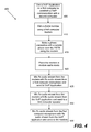
- FIG. 4 illustrates a flow diagram of a VoIP call forwarding method over the PSTN network for use by the VoIP system of FIG. 2 , according to one embodiment of the present invention
- FIG. 5 illustrates a flow diagram of a first VoIP three-way calling method over the PSTN network for use by the VoIP system of FIG. 2 , according to one embodiment of the present invention
- FIG. 6 illustrates a flow diagram of a second VoIP three-way calling method over the PSTN network for use by the VoIP system of FIG. 2 , according to one embodiment of the present invention
- FIG. 7 illustrates a flow diagram of a first PSTN phone line status checking method for use by the VoIP system of FIG. 2 , according to one embodiment of the present invention
- FIG. 8 illustrates a flow diagram of a second PSTN phone line status checking method for use by the VoIP system of FIG. 2 , according to one embodiment of the present invention.
- FIG. 9 illustrates a flow diagram of a directory synchronization method for use by the VoIP system of FIG. 2 and a communication device, according to one embodiment of the present invention.
- FIG. 2 illustrates VoIP system 200 according to one embodiment of the present invention, which includes packet network 230 at its core for facilitating communications between first computer 210 and second computer 250 , where the computers can be standalone VoIP devices or PC-centric VoIP applications, and the like.
- first speech encoder/decoder 220 is located in first computer 210 and interposed between first VoIP application 215 and packet network 230
- second speech encoder/decoder 240 is located in second computer 250 and interposed between second computer 250 and packet network 230 .
- first speech encoder/decoder 220 and second speech encoder/decoder 240 are integrated within first VoIP application 215 and second VoIP application 255 , respectively.
- Each of first speech encoder/decoder 220 and second speech encoder/decoder 240 performs the tasks of receiving a speech signal from its corresponding user device, digitizing the speech signal, encoding or compressing the digitized speech signal, packetizing the compressed speech signal and transmitting speech packets over packet network 230 in one direction, and in the other direction, receiving speech packets over packet network 230 , depacketizing the compressed speech signal, decoding or decompressing the depacketized speech signal to retrieve the digitized speech signal to regenerate the speech signal and transmitting the speech signal to its corresponding user device.
- First computer 210 includes first VoIP application 215 , first modem audio subsystem 217 , first call forwarding application 218 and first modem 219 .
- second computer 250 includes second VoIP application 255 , second modem audio subsystem 257 , second call forwarding application 258 and second modem 259 .
- FIG. 3 illustrates modem 320 for use in VoIP system 200 as first modem 219 or second modem 259 , according to one embodiment of the present invention.
- modem 320 includes host interface 330 for interfacing with host 310 , such as first computer 210 or second computer 250 .
- host interface may be a computer bus interface.
- host interface may be a serial interface, such as an RS232 interface.
- modem 320 includes codec 340 for coding a signal for transmission over PSTN 360 to phone 280 , and for decoding a signal received over PSTN 360 .
- modem 320 includes data access arrangement (DAA) 350 for interfacing with the telephone line for communication over PSTN 360 .
- DAA data access arrangement
- DSP and controller functions of modem 320 may be performed by host 310 ; however, in other embodiments either or both DSP and controller functions may be performed by modem 320 .
- modem 320 includes an audio mode for transmitting an audio stream from host 310 over PSTN 360 and for transmitting an audio stream to host 310 based on signals received over PSTN 360 .
- modem 320 may include data and facsimile functions in addition to the audio function.
- modem 320 may include a speakerphone mode, and modem 320 uses the speakerphone mode of the modem as the audio mode. In the speakerphone mode, modem 320 may enable an echo canceller. In one embodiment, modem 320 may enter the speakerphone mode, but disable the echo canceller if the VoIP application is running.
- FIG. 4 illustrates a flow diagram of VoIP call forwarding method 400 over PSTN network 270 for use by VoIP system 200 , according to one embodiment of the present invention.
- first VoIP application 215 establishes a VoIP connection with second VoIP application 255 establishes over packet network 230 .
- users of first VoIP application 215 and second VoIP application 255 may desire to add a third participant to the VoIP connection.
- the user of first computer 210 may request first computer 210 to contact the third participant over a PSTN phone line, and first computer 210 may use first modem 219 to dial a phone number of the participant on the PSTN phone line.
- the third participant answers the PSTN call using a wireless or a wireline communication device, such as phone 280 .
- first computer 210 places modem 219 in the audio mode, such that the audio stream is communicated between phone 280 and first VoIP application 215 via modem 219 over PSTN network 270 .
- first computer 210 replaces the first computer audio subsystem with first modem audio subsystem 217 .
- first modem audio subsystem 217 mixes the audio stream received from first modem 219 , which is based on Rx signal 203 , with the audio stream received from microphone 201 , and sends this mixed audio stream to first VoIP application 215 for transmission over packet network 230 . Furthermore, at step 430 , first modem audio subsystem 217 mixes the audio stream received from first modem 219 , which is based on Rx signal 203 , with the audio stream received from first VoIP application 215 , and sends this mixed audio stream to speaker 202 .
- first modem audio subsystem 217 mixes the audio stream received from microphone 201 with the audio stream received from first VoIP application 215 , and sends this mixed audio stream to first modem 219 for transmission via Tx signal 204 to phone 280 over PSTN network 270 .
- first modem audio subsystem 217 may apply adaptive gain control (AGC) to the audio stream based on the source. For example, first modem audio subsystem 217 may apply AGC to drop the audio level for the audio stream from microphone 201 prior to mixing with the audio stream from received from first modem 219 , or may increase the audio level for the audio stream received from first modem 219 .
- AGC adaptive gain control
- FIG. 5 illustrates a flow diagram of first VoIP three-way calling method 500 over PSTN network 270 for use by VoIP system 200 , according to one embodiment of the present invention.
- first VoIP application 215 establishes a VoIP connection with second VoIP application 255 establishes over packet network 230 .
- a user of first VoIP application 215 receives a call from phone 280 over PSTN network 270 on his PSTN phone line while the user is in communication with VoIP application 255 over packet network 230 .
- the user of first VoIP application 215 answers the call from phone 280 using his telephone.
- the user of first VoIP application 215 decides to establish a three-way call between the call from phone 280 over PSTN network 270 and the ongoing call between first VoIP application 215 and second VoIP application 255 over packet network 230 .
- the user of first VoIP application 215 requests first computer 210 to establish this three-way call, and at step 520 , first computer 210 replaces first computer audio subsystem 116 with first modem audio subsystem 217 , and places first modem 219 in the audio mode, where first modem 219 shares the PSTN phone line with the user's telephone. Thereafter, first modem 219 goes off-hook and ceases the PSTN phone line, at which point the user may place the user's telephone on-hook.
- first modem audio subsystem 217 mixes the audio stream received from first modem 219 , which is based on Rx signal 203 , with the audio stream received from microphone 201 , and sends this mixed audio stream to first VoIP application 215 for transmission over packet network 230 . Furthermore, at step 530 , first modem audio subsystem 217 mixes the audio stream received from first modem 219 , which is based on Rx signal 203 , with the audio stream received from first VoIP application 215 , and sends this mixed audio stream to speaker 202 .
- first modem audio subsystem 217 mixes the audio stream received from microphone 201 with the audio stream received from first VoIP application 215 , and sends this mixed audio stream to first modem 219 for transmission via Tx signal 204 to phone 280 over PSTN network 270 .
- FIG. 6 illustrates a flow diagram of second VoIP three-way calling method 600 over PSTN network 270 for use by the VoIP system 200 , according to one embodiment of the present invention.
- a first user uses a local phone to place a call to phone 280 over PSTN network 280 . While in communication over PSTN network 270 , the first user decides to call another over packet network 230 and establish a three-way call, or the first user receives a VoIP call over packet network 230 and decides to establish a three-way call between the PSTN and the VoIP call.
- VoIP three-way calling method 600 moves to step 615 , where the first user requests first computer 210 to establish this three-way call, and first computer 210 replaces first computer audio subsystem 116 with first modem audio subsystem 217 , and places first modem 219 in the audio mode, where first modem 219 shares the PSTN phone line with the first user's telephone. Thereafter, first modem 219 goes off-hook and ceases the PSTN phone line, at which point the user may place the user's telephone on-hook.
- first modem audio subsystem 217 mixes the audio stream received from first modem 219 , which is based on Rx signal 203 , with the audio stream received from microphone 201 , and sends this mixed audio stream to first VoIP application 215 for transmission over packet network 230 . Furthermore, at step 625 , first modem audio subsystem 217 mixes the audio stream received from first modem 219 , which is based on Rx signal 203 , with the audio stream received from first VoIP application 215 , and sends this mixed audio stream to speaker 202 .
- first modem audio subsystem 217 mixes the audio stream received from microphone 201 with the audio stream received from first VoIP application 215 , and sends this mixed audio stream to first modem 219 for transmission via Tx signal 204 to phone 280 over PSTN network 270 .
- FIG. 7 illustrates a flow diagram of first PSTN phone line status checking method 700 for use by VoIP system 200 , according to one embodiment of the present invention.
- first VoIP application 215 receives a VoIP call from second VoIP application 255 to establish a VoIP communication session over packet network 230 .
- first VoIP application 215 determines that the user of first computer 210 is unavailable to answer the VoIP call after the user does not answer the VoIP call after a certain number of rings or a period of time.
- first call forwarding application 218 determines whether the user has a call forwarding phone number for communication over PSTN network 270 , and if so, first call forwarding application 218 requests first modem 219 to place a call to the user over PSTN network 270 at the call forwarding phone number.
- first modem 219 determines whether the PSTN phone line connected to first modem 219 is off-hook, such as being in use by another communication device, e.g. a facsimile machine, telephone, etc.
- another communication device e.g. a facsimile machine, telephone, etc.
- DAA 350 of modem 320 can be designed to detect whether the PSTN phone line is off-hook.
- first PSTN phone line status checking method 700 moves to step 725 , where first VoIP application 215 may forward the VoIP call to a voice mail, such that the VoIP caller may leave a message, or first VoIP application 215 may play a message for the VoIP caller informing that the user is unavailable, and that at this time the VoIP call cannot be forwarded to the user, because the line is busy but the VoIP may try again shortly.
- first VoIP application 215 may cause first modem 219 to go off-hook and play a message in the audio mode for the current user of the PSTN phone line that a VoIP call is waiting to be transferred, and prompt the current user as to whether the current user wishes to terminate its call in view of the VoIP call.
- first PSTN phone line status checking method 700 moves to step 730 , where first VoIP application 215 uses first modem 219 to dial the call forwarding number of the user on the PSTN phone line.
- the user answers the PSTN call using a wireless or a wireline communication device, such as phone 280 .
- first computer 210 places modem 219 in the audio mode, such that the audio stream is communicated between phone 280 and first VoIP application 215 via modem 219 over PSTN network 270 .
- first computer 210 replaces first computer audio subsystem with first modem audio subsystem 217 .
- FIG. 8 illustrates a flow diagram of second PSTN phone line status checking method 800 for use by VoIP system 200 , according to one embodiment of the present invention.
- first VoIP application 215 receives a VoIP call from second VoIP application 255 to establish a VoIP communication session over packet network 230 .
- first VoIP application 215 determines that the user of first computer 210 is unavailable to answer the VoIP call after the user does not answer the VoIP call after a certain number of rings or a period of time.
- first call forwarding application 218 determines that the user has a call forwarding phone number for communication over PSTN network 270 , and if so, first call forwarding application 218 requests first modem 219 to place a call to the user over PSTN network 270 at the call forwarding phone number, and first modem 219 dials the call forwarding number of the user on the PSTN phone line.
- the user answers the PSTN call using a wireless or a wireline communication device, such as phone 280 .
- first computer 210 places modem 219 in the audio mode, such that the audio stream is communicated between phone 280 and first VoIP application 215 via modem 219 over PSTN network 270 .
- first computer 210 replaces the first computer audio subsystem with first modem audio subsystem 217 .
- first modem 219 begins to monitor the PSTN phone line to detect an extension pick-up, i.e. to determine whether any other device connected to the PSTN phone line goes off-hook. Similar to the above-mentioned line-in-use detection, one of ordinary skilled in the art knows how DAA 350 of modem 320 can be designed to detect whether the PSTN phone line is taken off-hook. If, at step 835 , first modem 219 determines that another device connected to the PSTN phone line has gone off-hook, second PSTN phone line status checking method 800 moves to step 840 , where first computer 210 alerts such other device taking the PSTN phone line off-hook that the line is currently in use by playing an audio message through first modem 219 .
- first computer 210 may inquire as to whether the user of such other device would like to join the VoIP call. Further, at step 850 , first computer 210 may alert the VoIP users that another device has gone off-hook or picked up an extension. Next, at step 855 , first computer 210 may inquire as to whether the VoIP users would like the new user to join the VoIP call or would like to terminate the VoIP call.
- first PSTN phone line status checking method 700 and second PSTN phone line status checking method 800 may be used with other features of VoIP applications and are not limited to use with the call forwarding feature.
- line-in-use detection and extension pick-up steps may also be used in conjunction with the three-way calling feature.
- FIG. 9 illustrates a flow diagram of directory synchronization method 900 for use by the VoIP system of FIG. 2 and a communication device, such as a cellular phone, wireless PDA, or the like, according to one embodiment of the present invention.
- directory synchronization method 900 begins at step 905 , where a cellular phone is connected to first computer 210 via a communication interface, such as a USB port.
- a communication interface such as a USB port.
- step 910 after detecting that the cellular phone has been connected to first computer 210 , existence of first VoIP application, having a VoIP directory with remote user identifications, is detected.
- the VoIP directory may include user names and identification numbers, such as speed dial numbers.
- first VoIP application 215 directory may use “001” as the speed dial number for the first entry, “002” as the speed dial number for the second entry, and so on. Therefore, to request first VoIP application 215 to make a VoIP call to the remote user in the first entry, “001” should be sent to first VoIP application 215 .
- a directory synchronization request may be sent by the cellular phone.
- the directory synchronization request may also be sent by first computer 210 or first VoIP application 215 .
- a directory synchronization application (not shown) in the first computer 210 may first copy the directory contents of the cellular phone into first computer 210 memory, and new entries from first VoIP application 215 directory may be added to the copy of the cellular phone directory in first computer 210 memory.
- the directory synchronization application may add a new phone number for VoIP application calls.
- cellular phone directories typically include a home phone number, a cell phone number, and the like, for each name in the directory.
- a VoIP number is added and associated with each name in the copy of the cellular phone directory in first computer 210 memory.
- the VoIP number includes the PSTN phone number for calling the originating VoIP application, e.g. phone line connected to first modem 219 , and the VoIP identification number for each specific name in the directory, such as “001”, is appended to the PSTN phone number.
- a hard pause or a time delay pause may be inserted between the PSTN phone number and the VoIP identification number, such that sufficient time is provided for first modem 219 to answer the call and provide a prompt for receiving the VoIP identification number.
- the first VoIP number in the copy of the cellular phone directory may be stored as “1-800-555-1212P001”. It should be noted that in other embodiments, the PSTN phone number may be stored in a single location and each of the VoIP identification numbers may be stored in each of the corresponding directory location. Further, at step 920 , the edited copy of the cellular phone directory in first computer 210 memory is transmitted to the cellular phone and stored in the cellular phone directory.
- the cellular phone receives a request to make a call to a remote VoIP user via first VoIP application 215 .
- the cellular phone retrieves the appended VoIP number, including the PSTN phone number and the VoIP identification number, for the remote VoIP user from the cellular phone directory.
- the PSTN phone number may not be appended and stored along with the VoIP identification number. In such event, the PSTN phone number and the VoIP identification number are retrieved separately.
- the cellular phone dials the PSTN number portion of the VoIP number. For example, the cellular phone dials “1-800-555-1212”. Next, the cellular phone pauses or delays dialing the VoIP identification number, e.g. when “P” or pause is encountered in the string. After an appropriate amount of time has passed, the cellular phone dials digits “001”, which first modem 219 receives over the PSTN phone line, detects the corresponding DTMF tones for “001” and provides digits “001” to first call forwarding application 218 , which communicates with first VoIP application 215 for contacting the corresponding remote VoIP user. Accordingly, a user of the cellular phone may effortlessly contact remote VoIP users via the cellular phone directory that is synchronized with the VoIP phone directory to include the PSTN phone number and the VoIP identification number, e.g. appended and stored in the cellular phone directory.
Landscapes
- Engineering & Computer Science (AREA)
- Multimedia (AREA)
- Signal Processing (AREA)
- Computer Networks & Wireless Communication (AREA)
- Telephonic Communication Services (AREA)
Abstract
Description
Claims (22)
Priority Applications (1)
| Application Number | Priority Date | Filing Date | Title |
|---|---|---|---|
| US11/438,009 US9247069B1 (en) | 2006-05-19 | 2006-05-19 | Modem call forwarding and three-way calling features for VoIP applications |
Applications Claiming Priority (1)
| Application Number | Priority Date | Filing Date | Title |
|---|---|---|---|
| US11/438,009 US9247069B1 (en) | 2006-05-19 | 2006-05-19 | Modem call forwarding and three-way calling features for VoIP applications |
Publications (1)
| Publication Number | Publication Date |
|---|---|
| US9247069B1 true US9247069B1 (en) | 2016-01-26 |
Family
ID=55086325
Family Applications (1)
| Application Number | Title | Priority Date | Filing Date |
|---|---|---|---|
| US11/438,009 Active 2034-10-24 US9247069B1 (en) | 2006-05-19 | 2006-05-19 | Modem call forwarding and three-way calling features for VoIP applications |
Country Status (1)
| Country | Link |
|---|---|
| US (1) | US9247069B1 (en) |
Cited By (1)
| Publication number | Priority date | Publication date | Assignee | Title |
|---|---|---|---|---|
| US11677574B1 (en) * | 2020-07-02 | 2023-06-13 | Intrado Corporation | Automated conference sessions generated to manage application development |
Citations (14)
| Publication number | Priority date | Publication date | Assignee | Title |
|---|---|---|---|---|
| US20010015981A1 (en) * | 1996-11-22 | 2001-08-23 | Nelson Tracy Lee | System and method for transporting a call in a telecommunication network |
| US20010021248A1 (en) * | 2000-03-13 | 2001-09-13 | Katsunori Utsumi | Personal information verification method in call center |
| US20020032875A1 (en) * | 2000-07-28 | 2002-03-14 | Mehdi Kashani | Information processing apparatus and method |
| US20020085488A1 (en) * | 2000-12-28 | 2002-07-04 | Nec Corporation | Communication system and packet switching method thereof |
| US20020108484A1 (en) * | 1996-06-24 | 2002-08-15 | Arnold Rob C. | Electronic music instrument system with musical keyboard |
| US20030053451A1 (en) * | 1998-12-22 | 2003-03-20 | Sprint Communications Company, L.P. | System and method for connecting calls with a time division multiplex matrix |
| US20040018848A1 (en) * | 2002-07-26 | 2004-01-29 | Minoru Ogino | Wireless terminal device, communications system and communications control method |
| US20040198328A1 (en) * | 2002-08-27 | 2004-10-07 | Brandenberger Sarah M. | Call management for wireless mobile communication systems |
| US20040203373A1 (en) * | 2002-07-31 | 2004-10-14 | Minoru Ogino | Wireless terminal device, communications system, and communication control method |
| US20040266418A1 (en) * | 2003-06-27 | 2004-12-30 | Motorola, Inc. | Method and apparatus for controlling an electronic device |
| US20050234727A1 (en) * | 2001-07-03 | 2005-10-20 | Leo Chiu | Method and apparatus for adapting a voice extensible markup language-enabled voice system for natural speech recognition and system response |
| US20060153354A1 (en) * | 2002-05-20 | 2006-07-13 | David Brahm | Systems and methods for call screening |
| US20060187900A1 (en) * | 2005-02-22 | 2006-08-24 | Akbar Imran M | Method and system for providing private virtual secure Voice over Internet Protocol communications |
| US20070025338A1 (en) * | 2005-07-26 | 2007-02-01 | Smartlink Ltd.. | Software-based solutions for telephone network bridging |
-
2006
- 2006-05-19 US US11/438,009 patent/US9247069B1/en active Active
Patent Citations (14)
| Publication number | Priority date | Publication date | Assignee | Title |
|---|---|---|---|---|
| US20020108484A1 (en) * | 1996-06-24 | 2002-08-15 | Arnold Rob C. | Electronic music instrument system with musical keyboard |
| US20010015981A1 (en) * | 1996-11-22 | 2001-08-23 | Nelson Tracy Lee | System and method for transporting a call in a telecommunication network |
| US20030053451A1 (en) * | 1998-12-22 | 2003-03-20 | Sprint Communications Company, L.P. | System and method for connecting calls with a time division multiplex matrix |
| US20010021248A1 (en) * | 2000-03-13 | 2001-09-13 | Katsunori Utsumi | Personal information verification method in call center |
| US20020032875A1 (en) * | 2000-07-28 | 2002-03-14 | Mehdi Kashani | Information processing apparatus and method |
| US20020085488A1 (en) * | 2000-12-28 | 2002-07-04 | Nec Corporation | Communication system and packet switching method thereof |
| US20050234727A1 (en) * | 2001-07-03 | 2005-10-20 | Leo Chiu | Method and apparatus for adapting a voice extensible markup language-enabled voice system for natural speech recognition and system response |
| US20060153354A1 (en) * | 2002-05-20 | 2006-07-13 | David Brahm | Systems and methods for call screening |
| US20040018848A1 (en) * | 2002-07-26 | 2004-01-29 | Minoru Ogino | Wireless terminal device, communications system and communications control method |
| US20040203373A1 (en) * | 2002-07-31 | 2004-10-14 | Minoru Ogino | Wireless terminal device, communications system, and communication control method |
| US20040198328A1 (en) * | 2002-08-27 | 2004-10-07 | Brandenberger Sarah M. | Call management for wireless mobile communication systems |
| US20040266418A1 (en) * | 2003-06-27 | 2004-12-30 | Motorola, Inc. | Method and apparatus for controlling an electronic device |
| US20060187900A1 (en) * | 2005-02-22 | 2006-08-24 | Akbar Imran M | Method and system for providing private virtual secure Voice over Internet Protocol communications |
| US20070025338A1 (en) * | 2005-07-26 | 2007-02-01 | Smartlink Ltd.. | Software-based solutions for telephone network bridging |
Cited By (1)
| Publication number | Priority date | Publication date | Assignee | Title |
|---|---|---|---|---|
| US11677574B1 (en) * | 2020-07-02 | 2023-06-13 | Intrado Corporation | Automated conference sessions generated to manage application development |
Similar Documents
| Publication | Publication Date | Title |
|---|---|---|
| US7567549B2 (en) | Computer telephony integration adapter | |
| US9225626B2 (en) | System and method for providing virtual multiple lines in a communications system | |
| KR100338683B1 (en) | Integrated IP call router | |
| US20140139617A1 (en) | Systems and methods for implementing internet video conferencing using standard phone calls | |
| JP4646657B2 (en) | TV phone adapter | |
| JP2002512738A (en) | Phone doubler device | |
| JPH10322462A (en) | Network telephone system and its method | |
| KR20050012255A (en) | Terminal connection device, connection control device, and multi-function telephone terminal | |
| JP5197746B2 (en) | Method, modem, and server for bridging telephone calls to Internet calls | |
| US8116442B2 (en) | Method and apparatus for audio conference bridge initiated remote device muting | |
| US6603965B1 (en) | Pervasive voice handset system | |
| US20040156493A1 (en) | Method and apparatus for providing a central telephony service for a calling party at the called party telephone | |
| US9042526B2 (en) | Method and apparatus for enabling a calling party to leave a voice message for a called party in response to a command provided by the calling party | |
| US8537996B2 (en) | Selective response unit | |
| KR100552521B1 (en) | apparatus and method of voice messaging service in VoIP system | |
| US7436819B2 (en) | Communication apparatus and control method thereof | |
| US9247069B1 (en) | Modem call forwarding and three-way calling features for VoIP applications | |
| CA2705961C (en) | Method and apparatus for enabling a calling party to leave a voice message for a called party | |
| US20080123629A1 (en) | Apparatus and Method For Automatic Call Back | |
| EP1059796A2 (en) | Rerouting telephone calls over the Internet during an active Internet sessions | |
| JP2003309588A (en) | Ip communication system urging ip address registration by incoming call of number display service, and gate keeper and terminal device constituting the ip communication system | |
| CN101110751A (en) | IP PBX based on P2P technology | |
| WO2004049655A1 (en) | System and method for voice over ip communication | |
| KR100467445B1 (en) | System and method for picture phone service | |
| US8204178B1 (en) | Method to prevent TTY/TDD probing and unwanted TTY/TDD tone generation on voice gateways |
Legal Events
| Date | Code | Title | Description |
|---|---|---|---|
| AS | Assignment |
Owner name: CONEXANT SYSTEMS, INC., CALIFORNIA Free format text: ASSIGNMENT OF ASSIGNORS INTEREST;ASSIGNORS:WEBSTER, ANDREW B;DAVID, EITAN;MCINTYRE, STEPHEN J.;REEL/FRAME:017908/0208 Effective date: 20060515 |
|
| AS | Assignment |
Owner name: BANK OF NEW YORK TRUST COMPANY, N.A., ILLINOIS Free format text: SECURITY AGREEMENT;ASSIGNOR:CONEXANT SYSTEMS, INC.;REEL/FRAME:018711/0818 Effective date: 20061113 |
|
| AS | Assignment |
Owner name: CONEXANT SYSTEMS, INC., CALIFORNIA Free format text: RELEASE BY SECURED PARTY;ASSIGNOR:THE BANK OF NEW YORK MELLON TRUST COMPANY, N.A. (FORMERLY, THE BANK OF NEW YORK TRUST COMPANY, N.A.);REEL/FRAME:023998/0838 Effective date: 20100128 |
|
| AS | Assignment |
Owner name: THE BANK OF NEW YORK MELLON TRUST COMPANY, N.A., I Free format text: SECURITY AGREEMENT;ASSIGNORS:CONEXANT SYSTEMS, INC.;CONEXANT, INC.;CONEXANT SYSTEMS WORLDWIDE, INC.;AND OTHERS;REEL/FRAME:024492/0339 Effective date: 20100310 |
|
| STCF | Information on status: patent grant |
Free format text: PATENTED CASE |
|
| AS | Assignment |
Owner name: BROOKTREE BROADBAND HOLDING, INC., CALIFORNIA Free format text: RELEASE BY SECURED PARTY;ASSIGNOR:THE BANK OF NEW YORK MELLON TRUST COMPANY, N.A.;REEL/FRAME:038631/0452 Effective date: 20140310 Owner name: CONEXANT SYSTEMS WORLDWIDE, INC., CALIFORNIA Free format text: RELEASE BY SECURED PARTY;ASSIGNOR:THE BANK OF NEW YORK MELLON TRUST COMPANY, N.A.;REEL/FRAME:038631/0452 Effective date: 20140310 Owner name: CONEXANT, INC., CALIFORNIA Free format text: RELEASE BY SECURED PARTY;ASSIGNOR:THE BANK OF NEW YORK MELLON TRUST COMPANY, N.A.;REEL/FRAME:038631/0452 Effective date: 20140310 Owner name: CONEXANT SYSTEMS, INC., CALIFORNIA Free format text: RELEASE BY SECURED PARTY;ASSIGNOR:THE BANK OF NEW YORK MELLON TRUST COMPANY, N.A.;REEL/FRAME:038631/0452 Effective date: 20140310 |
|
| AS | Assignment |
Owner name: LAKESTAR SEMI INC., NEW YORK Free format text: CHANGE OF NAME;ASSIGNOR:CONEXANT SYSTEMS, INC.;REEL/FRAME:038777/0885 Effective date: 20130712 |
|
| AS | Assignment |
Owner name: CONEXANT SYSTEMS, INC., CALIFORNIA Free format text: ASSIGNMENT OF ASSIGNORS INTEREST;ASSIGNOR:LAKESTAR SEMI INC.;REEL/FRAME:038803/0693 Effective date: 20130712 |
|
| AS | Assignment |
Owner name: CONEXANT SYSTEMS, LLC, CALIFORNIA Free format text: CHANGE OF NAME;ASSIGNOR:CONEXANT SYSTEMS, INC.;REEL/FRAME:042986/0613 Effective date: 20170320 |
|
| AS | Assignment |
Owner name: SYNAPTICS INCORPORATED, CALIFORNIA Free format text: ASSIGNMENT OF ASSIGNORS INTEREST;ASSIGNOR:CONEXANT SYSTEMS, LLC;REEL/FRAME:043786/0267 Effective date: 20170901 |
|
| AS | Assignment |
Owner name: WELLS FARGO BANK, NATIONAL ASSOCIATION, NORTH CAROLINA Free format text: SECURITY INTEREST;ASSIGNOR:SYNAPTICS INCORPORATED;REEL/FRAME:044037/0896 Effective date: 20170927 Owner name: WELLS FARGO BANK, NATIONAL ASSOCIATION, NORTH CARO Free format text: SECURITY INTEREST;ASSIGNOR:SYNAPTICS INCORPORATED;REEL/FRAME:044037/0896 Effective date: 20170927 |
|
| MAFP | Maintenance fee payment |
Free format text: PAYMENT OF MAINTENANCE FEE, 4TH YEAR, LARGE ENTITY (ORIGINAL EVENT CODE: M1551); ENTITY STATUS OF PATENT OWNER: LARGE ENTITY Year of fee payment: 4 |
|
| MAFP | Maintenance fee payment |
Free format text: PAYMENT OF MAINTENANCE FEE, 8TH YEAR, LARGE ENTITY (ORIGINAL EVENT CODE: M1552); ENTITY STATUS OF PATENT OWNER: LARGE ENTITY Year of fee payment: 8 |