US9243831B2 - Heat exchanging system - Google Patents
Heat exchanging system Download PDFInfo
- Publication number
- US9243831B2 US9243831B2 US13/822,602 US201113822602A US9243831B2 US 9243831 B2 US9243831 B2 US 9243831B2 US 201113822602 A US201113822602 A US 201113822602A US 9243831 B2 US9243831 B2 US 9243831B2
- Authority
- US
- United States
- Prior art keywords
- heat exchanger
- temperature
- pathway
- temperature adjustment
- cooling
- Prior art date
- Legal status (The legal status is an assumption and is not a legal conclusion. Google has not performed a legal analysis and makes no representation as to the accuracy of the status listed.)
- Expired - Fee Related, expires
Links
- 238000001816 cooling Methods 0.000 claims abstract description 157
- 230000037361 pathway Effects 0.000 claims abstract description 103
- 239000007788 liquid Substances 0.000 claims description 41
- 238000002347 injection Methods 0.000 claims description 37
- 239000007924 injection Substances 0.000 claims description 37
- 239000007921 spray Substances 0.000 claims description 11
- 238000011144 upstream manufacturing Methods 0.000 claims description 9
- 238000007599 discharging Methods 0.000 claims description 6
- 230000002093 peripheral effect Effects 0.000 claims description 6
- 239000000110 cooling liquid Substances 0.000 claims 5
- 239000003507 refrigerant Substances 0.000 abstract description 125
- 238000004378 air conditioning Methods 0.000 abstract description 98
- XLYOFNOQVPJJNP-UHFFFAOYSA-N water Substances O XLYOFNOQVPJJNP-UHFFFAOYSA-N 0.000 abstract description 81
- 230000005611 electricity Effects 0.000 description 23
- 238000010438 heat treatment Methods 0.000 description 22
- 230000000694 effects Effects 0.000 description 16
- 238000009833 condensation Methods 0.000 description 13
- 230000005494 condensation Effects 0.000 description 13
- 239000003595 mist Substances 0.000 description 11
- 230000007613 environmental effect Effects 0.000 description 9
- 238000010586 diagram Methods 0.000 description 7
- 239000002245 particle Substances 0.000 description 7
- 230000006837 decompression Effects 0.000 description 6
- 238000005507 spraying Methods 0.000 description 6
- 230000006835 compression Effects 0.000 description 5
- 238000007906 compression Methods 0.000 description 5
- 230000009467 reduction Effects 0.000 description 5
- 230000008016 vaporization Effects 0.000 description 5
- 238000009834 vaporization Methods 0.000 description 5
- 239000003673 groundwater Substances 0.000 description 4
- 230000008901 benefit Effects 0.000 description 3
- PXBRQCKWGAHEHS-UHFFFAOYSA-N dichlorodifluoromethane Chemical compound FC(F)(Cl)Cl PXBRQCKWGAHEHS-UHFFFAOYSA-N 0.000 description 3
- 239000007791 liquid phase Substances 0.000 description 3
- 239000002699 waste material Substances 0.000 description 3
- CBENFWSGALASAD-UHFFFAOYSA-N Ozone Chemical compound [O-][O+]=O CBENFWSGALASAD-UHFFFAOYSA-N 0.000 description 2
- 238000007710 freezing Methods 0.000 description 2
- 230000008014 freezing Effects 0.000 description 2
- 238000005057 refrigeration Methods 0.000 description 2
- 238000010257 thawing Methods 0.000 description 2
- 239000002351 wastewater Substances 0.000 description 2
- 101000582320 Homo sapiens Neurogenic differentiation factor 6 Proteins 0.000 description 1
- 102100030589 Neurogenic differentiation factor 6 Human genes 0.000 description 1
- 230000004075 alteration Effects 0.000 description 1
- 238000006243 chemical reaction Methods 0.000 description 1
- 230000003750 conditioning effect Effects 0.000 description 1
- 230000006378 damage Effects 0.000 description 1
- 230000007423 decrease Effects 0.000 description 1
- 238000012423 maintenance Methods 0.000 description 1
- 238000004519 manufacturing process Methods 0.000 description 1
- 230000008439 repair process Effects 0.000 description 1
- 230000000630 rising effect Effects 0.000 description 1
- 239000000243 solution Substances 0.000 description 1
- 239000008399 tap water Substances 0.000 description 1
- 235000020679 tap water Nutrition 0.000 description 1
Images


Classifications
-
- F—MECHANICAL ENGINEERING; LIGHTING; HEATING; WEAPONS; BLASTING
- F25—REFRIGERATION OR COOLING; COMBINED HEATING AND REFRIGERATION SYSTEMS; HEAT PUMP SYSTEMS; MANUFACTURE OR STORAGE OF ICE; LIQUEFACTION SOLIDIFICATION OF GASES
- F25B—REFRIGERATION MACHINES, PLANTS OR SYSTEMS; COMBINED HEATING AND REFRIGERATION SYSTEMS; HEAT PUMP SYSTEMS
- F25B49/00—Arrangement or mounting of control or safety devices
- F25B49/02—Arrangement or mounting of control or safety devices for compression type machines, plants or systems
-
- F—MECHANICAL ENGINEERING; LIGHTING; HEATING; WEAPONS; BLASTING
- F25—REFRIGERATION OR COOLING; COMBINED HEATING AND REFRIGERATION SYSTEMS; HEAT PUMP SYSTEMS; MANUFACTURE OR STORAGE OF ICE; LIQUEFACTION SOLIDIFICATION OF GASES
- F25B—REFRIGERATION MACHINES, PLANTS OR SYSTEMS; COMBINED HEATING AND REFRIGERATION SYSTEMS; HEAT PUMP SYSTEMS
- F25B6/00—Compression machines, plants or systems, with several condenser circuits
- F25B6/04—Compression machines, plants or systems, with several condenser circuits arranged in series
-
- F—MECHANICAL ENGINEERING; LIGHTING; HEATING; WEAPONS; BLASTING
- F28—HEAT EXCHANGE IN GENERAL
- F28D—HEAT-EXCHANGE APPARATUS, NOT PROVIDED FOR IN ANOTHER SUBCLASS, IN WHICH THE HEAT-EXCHANGE MEDIA DO NOT COME INTO DIRECT CONTACT
- F28D5/00—Heat-exchange apparatus having stationary conduit assemblies for one heat-exchange medium only, the media being in contact with different sides of the conduit wall, using the cooling effect of natural or forced evaporation
-
- F—MECHANICAL ENGINEERING; LIGHTING; HEATING; WEAPONS; BLASTING
- F28—HEAT EXCHANGE IN GENERAL
- F28D—HEAT-EXCHANGE APPARATUS, NOT PROVIDED FOR IN ANOTHER SUBCLASS, IN WHICH THE HEAT-EXCHANGE MEDIA DO NOT COME INTO DIRECT CONTACT
- F28D7/00—Heat-exchange apparatus having stationary tubular conduit assemblies for both heat-exchange media, the media being in contact with different sides of a conduit wall
- F28D7/0008—Heat-exchange apparatus having stationary tubular conduit assemblies for both heat-exchange media, the media being in contact with different sides of a conduit wall the conduits for one medium being in heat conductive contact with the conduits for the other medium
- F28D7/0016—Heat-exchange apparatus having stationary tubular conduit assemblies for both heat-exchange media, the media being in contact with different sides of a conduit wall the conduits for one medium being in heat conductive contact with the conduits for the other medium the conduits for one medium or the conduits for both media being bent
-
- F—MECHANICAL ENGINEERING; LIGHTING; HEATING; WEAPONS; BLASTING
- F28—HEAT EXCHANGE IN GENERAL
- F28D—HEAT-EXCHANGE APPARATUS, NOT PROVIDED FOR IN ANOTHER SUBCLASS, IN WHICH THE HEAT-EXCHANGE MEDIA DO NOT COME INTO DIRECT CONTACT
- F28D7/00—Heat-exchange apparatus having stationary tubular conduit assemblies for both heat-exchange media, the media being in contact with different sides of a conduit wall
- F28D7/10—Heat-exchange apparatus having stationary tubular conduit assemblies for both heat-exchange media, the media being in contact with different sides of a conduit wall the conduits being arranged one within the other, e.g. concentrically
- F28D7/106—Heat-exchange apparatus having stationary tubular conduit assemblies for both heat-exchange media, the media being in contact with different sides of a conduit wall the conduits being arranged one within the other, e.g. concentrically consisting of two coaxial conduits or modules of two coaxial conduits
-
- F—MECHANICAL ENGINEERING; LIGHTING; HEATING; WEAPONS; BLASTING
- F25—REFRIGERATION OR COOLING; COMBINED HEATING AND REFRIGERATION SYSTEMS; HEAT PUMP SYSTEMS; MANUFACTURE OR STORAGE OF ICE; LIQUEFACTION SOLIDIFICATION OF GASES
- F25B—REFRIGERATION MACHINES, PLANTS OR SYSTEMS; COMBINED HEATING AND REFRIGERATION SYSTEMS; HEAT PUMP SYSTEMS
- F25B13/00—Compression machines, plants or systems, with reversible cycle
-
- F—MECHANICAL ENGINEERING; LIGHTING; HEATING; WEAPONS; BLASTING
- F25—REFRIGERATION OR COOLING; COMBINED HEATING AND REFRIGERATION SYSTEMS; HEAT PUMP SYSTEMS; MANUFACTURE OR STORAGE OF ICE; LIQUEFACTION SOLIDIFICATION OF GASES
- F25B—REFRIGERATION MACHINES, PLANTS OR SYSTEMS; COMBINED HEATING AND REFRIGERATION SYSTEMS; HEAT PUMP SYSTEMS
- F25B2313/00—Compression machines, plants or systems with reversible cycle not otherwise provided for
- F25B2313/021—Indoor unit or outdoor unit with auxiliary heat exchanger not forming part of the indoor or outdoor unit
-
- F—MECHANICAL ENGINEERING; LIGHTING; HEATING; WEAPONS; BLASTING
- F25—REFRIGERATION OR COOLING; COMBINED HEATING AND REFRIGERATION SYSTEMS; HEAT PUMP SYSTEMS; MANUFACTURE OR STORAGE OF ICE; LIQUEFACTION SOLIDIFICATION OF GASES
- F25B—REFRIGERATION MACHINES, PLANTS OR SYSTEMS; COMBINED HEATING AND REFRIGERATION SYSTEMS; HEAT PUMP SYSTEMS
- F25B2339/00—Details of evaporators; Details of condensers
- F25B2339/04—Details of condensers
- F25B2339/047—Water-cooled condensers
-
- F—MECHANICAL ENGINEERING; LIGHTING; HEATING; WEAPONS; BLASTING
- F25—REFRIGERATION OR COOLING; COMBINED HEATING AND REFRIGERATION SYSTEMS; HEAT PUMP SYSTEMS; MANUFACTURE OR STORAGE OF ICE; LIQUEFACTION SOLIDIFICATION OF GASES
- F25B—REFRIGERATION MACHINES, PLANTS OR SYSTEMS; COMBINED HEATING AND REFRIGERATION SYSTEMS; HEAT PUMP SYSTEMS
- F25B2400/00—General features or devices for refrigeration machines, plants or systems, combined heating and refrigeration systems or heat-pump systems, i.e. not limited to a particular subgroup of F25B
- F25B2400/06—Several compression cycles arranged in parallel
-
- F—MECHANICAL ENGINEERING; LIGHTING; HEATING; WEAPONS; BLASTING
- F25—REFRIGERATION OR COOLING; COMBINED HEATING AND REFRIGERATION SYSTEMS; HEAT PUMP SYSTEMS; MANUFACTURE OR STORAGE OF ICE; LIQUEFACTION SOLIDIFICATION OF GASES
- F25B—REFRIGERATION MACHINES, PLANTS OR SYSTEMS; COMBINED HEATING AND REFRIGERATION SYSTEMS; HEAT PUMP SYSTEMS
- F25B2700/00—Sensing or detecting of parameters; Sensors therefor
- F25B2700/21—Temperatures
- F25B2700/2116—Temperatures of a condenser
- F25B2700/21161—Temperatures of a condenser of the fluid heated by the condenser
Definitions
- the present invention relates to heat exchanging systems, and in particular to heat exchanging systems that have configurations aimed at reducing environmental burden.
- An air conditioning system has a configuration where a refrigerant repeatedly absorbs and radiates heat while circulating between an indoor unit and an outdoor unit.
- the air conditioning system relating to the conventional art comprises an indoor unit 91 and an outdoor unit 92 that are connected to one another by refrigerant piping L 91 and L 97 .
- the indoor unit 91 is provided with a heat exchanger that functions as an evaporator during cooling, and an expansion valve.
- the outdoor unit 92 is provided with a compressor 921 , a condenser 922 , and a flow pathway switching part 923 .
- the compressor 921 and the flow pathway switching part 923 are connected by refrigerant piping L 92
- the condenser 922 and the flow pathway switching part 923 are connected by refrigerant piping L 93 and L 94 .
- the outdoor unit 92 is further provided with an additional heat exchanger 93 .
- the additional heat exchanger 93 is connected to the flow pathway switching part 923 in the outdoor unit 92 by refrigerant piping L 95 and L 96 .
- FIG. 10 shows an example of a circulation pathway (cycle) of a refrigerant during cooling.
- the present invention has been achieved in view of the above problems, and an aim thereof is to provide a heat exchanging system that is able to achieve improved heat exchange efficiency in a wide range of environmental conditions. Specifically, the present invention aims to improve heat exchange efficiency of existing air-cooling type heat exchanging systems cheaply and simply.
- the present invention is configured as described below.
- a heat exchanging system relating to the present invention comprises: a compressor; a first heat exchanger that functions as a condenser during cooling; a second heat exchanger that functions as an evaporator during cooling; and a temperature adjustment device that performs temperature adjustment of a heat carrier using a liquid, wherein the compressor, the first heat exchanger and the second heat exchanger are provided in a circulation pathway of the heat carrier, in respective order during cooling, and the temperature adjustment device is provided on (i) the first heat exchanger, or (ii) a section of the circulation pathway that during cooling is downstream of the first heat exchanger and upstream of the second heat exchanger.
- the heat exchanging system relating to the present invention comprises: a plurality of compressors; a plurality of first heat exchangers that each function as a condenser during cooling; a plurality of second heat exchangers that each function as an evaporator during cooling; a plurality of third heat exchangers; and a temperature adjustment device that performs temperature adjustment of a heat carrier using a liquid and that is provided with a tank for storing the liquid, wherein one of the compressors, one of the first heat exchangers and one of the second heat exchangers are provided in each of a plurality of independent circulation pathways of the heat carrier, in respective order during cooling, one of the third heat exchangers is provided in each of the plurality of independent circulation pathways at a point that during cooling is downstream of the first heat exchanger and upstream of the second heat exchanger, and the plurality of third heat exchangers are each contained within the tank provided in the temperature adjustment device.
- the temperature adjustment device that performs temperature adjustment of the heat carrier using the liquid, is provided on (i) the first heat exchanger, or (ii) the section of the circulation pathway that during cooling is downstream of the first heat exchanger and upstream of the second heat exchanger. Therefore, for the second heat exchanger, compared to the heat exchanging (air conditioning) system relating to the conventional art where heat exchange is with air, compression and condensation of the heat carrier (refrigerant) can be performed with little effect from environmental conditions, and thus electricity consumption can be reduced. The above is due to the temperature adjustment device performing temperature adjustment using the liquid, and thus compression and condensation of the heat carrier not being easily influenced by environmental conditions.
- the heat exchanging system relating to the present invention can be achieved simply by adding the temperature adjustment device to an existing heat exchanging system. Therefore equipment costs are reduced by continued use of the existing heat exchanging system. Due to the configuration relating to the present invention being achieved simply by adding the temperature adjustment device to the existing heat exchanging system, and also due to maintenance of the temperature adjustment device being simple, the heat exchanging system relating to the present invention may be used widely while also providing reduced equipment costs.
- the heat exchanging system relating to the present invention can perform heat exchange efficiently in a wide range of environmental conditions, therefore an advantageous effect of the present invention is high heat exchange efficiency.
- the heat exchanging system relating to the present invention may be applicable for air conditioning systems, refrigeration systems, freezing systems and the like.
- the heat exchanging system relating to the present invention may further comprise a third heat exchanger, provided in the circulation pathway at a point that during cooling is downstream of the first heat exchanger and upstream of the second heat exchanger, wherein the temperature adjustment device is provided with a tank for storing the liquid, and the third heat exchanger is contained within the tank.
- the third heat exchanger is contained within the tank of the temperature adjustment device, and temperature adjustment can be performed using the liquid in the temperature adjustment device. Therefore, compression and condensation of the heat carrier can be achieved reliably with little effect from environmental conditions, and electricity consumption can be further reduced. Furthermore, the third heat exchanger is provided in addition to the first heat exchanger and may be smaller in size than the first heat exchanger, therefore electricity consumption can be reduced without needing to significantly increase size of the system.
- the heat exchanging system relating to the present invention may further comprise: a first temperature sensor configured to measure temperature of the heat carrier at an output side, during cooling, of the third heat exchanger; a second temperature sensor configured to measure temperature in the tank; a third temperature sensor configured to measure peripheral temperature of the first heat exchanger; a fourth temperature sensor configured to measure temperature of the liquid supplied into the tank of the temperature adjustment device; and a control device configured to control a temperature adjustment condition of the temperature adjustment device, based on temperature information indicating the respective temperatures measured by the first, second, third and fourth temperature sensors.
- the control device causes the temperature adjustment device to operate at an optimal temperature adjustment condition, thus decompression and condensation can be performed reliably, and electricity consumption can be further reduced.
- the tank of the temperature adjustment device may be connected to an injection pathway for supplying the liquid thereto, and a discharge pathway for discharging the liquid therefrom, the injection pathway and the discharge pathway may each be provided with a control valve for controlling flow volume of the liquid therethrough, and the control device may control the temperature adjustment condition of the temperature adjustment device, based on the temperature information of the first, second, third and fourth temperature sensors, through open/close control of each of the two control valves.
- temperature adjustment can be reliably controlled based on the measured temperatures, by controlling supply flow volume and discharge flow volume of the liquid.
- the control device may open the control valve provided in the injection pathway and may close the control valve provided in the discharge pathway.
- the tank in the temperature adjustment device may be connected to an injection pathway for supplying the liquid therein, and a discharge pathway for discharging the liquid therefrom, at least one spray outlet, that sprays the liquid against the third heat exchanger, may be provided on a section of the injection pathway extending into the tank, the injection pathway may be provided with a control valve for controlling flow volume of the liquid therethrough, and the control device may control the temperature adjustment condition of the temperature adjustment device through open/close control of the control valve.
- volume of the liquid used can be reduced, and a high degree of control of temperature adjustment can be achieved through heat of vaporization effects.
- the heat exchanging system relating to the present invention may have a configuration wherein, the respective temperatures measured by the first, second, third and fourth temperature sensors are T 1 , T 2 , T 3 and T 4 , and when judging that conditions shown below in MATH 4-6 are all satisfied, the control device may open the control valve provided in the injection pathway.
- the temperature adjustment device may include a coil-type heat exchanger or a Liebig type heat exchanger, provided on piping that during cooling is between the third heat exchanger and the second heat exchanger in the circulation pathway.
- the heat exchanging system relating to the present invention may further comprise: a first pressure sensor provided in the circulation pathway at a point between the third heat exchanger and the second heat exchanger, and configured to measure pressure of the heat carrier thereat; a second pressure sensor provided in the circulation pathway at a point between the second heat exchanger and the compressor, and configured to measure pressure of the heat carrier thereat; and a control device configured to control a temperature adjustment condition of the temperature adjustment device, based on pressure information indicating the respective pressures measured by the first and second pressure sensors.
- control of temperature adjustment may be performed by controlling flow of the liquid based on the pressure information of the heat carrier such as in the configuration above. If the configuration above is adopted, decompression and condensation can be performed more reliably, and electricity consumption can be reduced in the same way as described above. In the above configuration only two pressure sensors are necessary, thus costs can be further reduced.
- each of the third heat exchangers may be contained within a single tank. Therefore, in addition to the effects described above, equipment cost and system size can both be reduced.
- FIG. 1 is a schematic block diagram showing configuration of an air conditioning system 1 relating to a first embodiment of the present invention.
- FIG. 2 is a flow chart showing control performed by a control device 15 in the air conditioning system 1 during cooling.
- FIG. 3 is a schematic block diagram showing configuration of the air conditioning system 1 during heating.
- FIG. 4 is a schematic diagram showing a part which is a feature of an air conditioning system 2 relating to a second embodiment of the present invention.
- FIG. 5 is a schematic block diagram showing configuration of an air conditioning system 3 relating to a third embodiment of the present invention.
- FIG. 6 is a schematic block diagram showing configuration of an air conditioning system 4 relating to a fourth embodiment of the present invention.
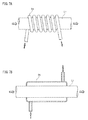
- FIG. 7A is a schematic perspective view showing configuration of part of a cooling device relating to a first modified example
- FIG. 7B is a schematic cross-sectional view showing configuration of part of a cooling device relating to a second modified example.
- FIG. 8 is a schematic block diagram showing configuration of an air conditioning system 7 relating to a fifth embodiment of the present invention.
- FIG. 9 is a flow chart showing control performed by a control device 75 in the air conditioning system 7 during cooling.
- FIG. 10 is a schematic block diagram showing configuration of an air conditioning system relating to a conventional art.
- FIG. 1 An air conditioning system 1 is adopted as an example of the heat exchanging system.
- the air conditioning system 1 includes an indoor unit 11 , an outdoor unit 12 , an additional heat exchanger 13 , a cooling device 14 , and a control device 15 .
- the outdoor unit 12 is connected to the indoor unit 11 through refrigerant piping L 1 , and includes a compressor 121 , a condenser 122 , and flow pathway switching valves 123 and 124 .
- the indoor unit 11 includes a heat exchanger that functions as an evaporator during cooling, and an expansion valve such as a capillary tube (omitted in the drawings). It is not essential that the expansion valve be a configuration element of the indoor unit 11 , and alternatively the expansion valve may for example be inserted through refrigerant piping L 7 .
- the compressor 121 and the flow pathway switching valve 123 are connected through refrigerant piping L 2
- the flow switching valve 123 and the condenser 122 are connected through refrigerant piping L 3
- the condenser 122 of the outdoor unit 12 is connected to the additional heat exchanger 13 through refrigerant piping L 4 , the flow pathway switching valve 124 , and refrigerant piping L 5 .
- the additional heat exchanger 13 and the indoor unit 11 are connected through the refrigerant piping L 7 .
- FIG. 1 shows connections during cooling, when the refrigerant piping L 2 is connected to the refrigerant piping L 3 through the flow pathway switching valve 123 , and the refrigerant piping L 4 is connected to the refrigerant piping L 5 through the flow pathway switching valve 124 . Consequently, refrigerant does not flow through the refrigerant piping L 6 during cooling.
- the additional heat exchanger 13 is provided in the circulation pathway of the refrigerant at a position that during cooling is between the condenser 122 of the outdoor unit 12 , and the indoor unit 11 .
- the additional heat exchanger 13 is contained within a cooling tank 141 in the cooling device 14 .
- the cooling device 14 also includes a water injection pathway 142 , a water outlet 143 , a water discharge pathway 144 , and control valves 145 and 146 which are positioned on the water injection pathway 142 and the water discharge pathway 144 respectively.
- the control valves 145 and 146 each open and close based on a control signal from the control device 15 .
- the control device 15 is connected to a plurality of temperature sensors 161 - 165 through signal wires, thus allowing temperature information indicating temperatures measured by the temperature sensors 161 - 165 to be input into the control device 15 .
- the temperature sensor 161 is provided adjacent to the condenser 122 of the outdoor unit 12 so as to measure peripheral temperature of the condenser 122 .
- the temperature sensor 162 is provided on the refrigerant piping L 5 so as to measure temperature of the refrigerant flowing through the refrigerant piping L 5 .
- the temperature sensor 163 is provided on the refrigerant piping L 7 so as to measure temperature of the refrigerant flowing through the refrigerant piping L 7 .
- the above configuration means that during cooling the temperature sensor 162 measures temperature of the refrigerant at an inlet to the additional heat exchanger 13 and the temperature sensor 163 measures temperature of the refrigerant at an outlet from the additional heat exchanger 13 .
- the temperature sensor 161 is provided adjacent to the condenser 122 of the outdoor unit 12 , but the temperature sensor 161 is not limited to being positioned as described above. Alternatively, the temperature sensor 161 may be provided separated from the condenser 122 and may measure outdoor temperature.
- the temperature sensor 164 is provided on the water injection pathway 142 of the cooling device 14 so as to measure temperature of water flowing through the water injection pathway 142 .
- Temperature sensor 165 is provided in the cooling tank 141 of the cooling device 14 so as to measure temperature inside the cooling tank 141 .
- a flare nut which is omitted in the drawings, is provided on a part of each of the refrigerant piping L 5 and the refrigerant piping L 7 that inserts into the cooling tank 141 .
- the above configuration allows easy repair and replacement of the additional heat exchanger 13 .
- the air conditioning system 1 has a configuration where the indoor unit 11 , the outdoor unit 12 and the additional heat exchanger 13 are provided in the circulation pathway of the refrigerant, and the cooling device 14 , controlled by the control device 15 , is provided as an attachment onto the additional heat exchanger 13 .
- decompression and condensation are performed in two steps through the condenser 122 of the outdoor unit 12 and the additional heat exchanger 13 . Therefore, electricity consumption can be reduced. Furthermore, by providing the additional heat exchanger 13 at a position in the circulation pathway of the refrigerant that is downstream of the condenser 1 during cooling, the refrigerant can be compressed more reliably than if the additional heat exchanger 13 is provided at a position upstream of the condenser 122 . Also, through the above configuration, refrigerant in the condenser 122 is mostly in liquid phase, reducing load on the compressor 121 . The refrigerant in the condenser 122 being in liquid phase allows reduction in load due to environmental conditions and realization of high heat exchange efficiency.
- the additional heat exchanger 13 is contained within the cooling tank 141 of the cooling device 14 , and temperature adjustment (cooling) can be performed using the water in the cooling device 14 .
- temperature adjustment cooling
- the above configuration allows more reliable compression and condensation of the refrigerant, and reduced electricity consumption.
- a liquid (water) for temperature adjustment which has relatively small variation in temperature compared to outdoor temperature, compression and condensation of the refrigerant can be performed with little effect from environmental conditions, compared to when heat exchange is with air.
- the air conditioning system 1 relating to the present embodiment is configured so that, when water supplied into the cooling tank 141 is at least equal to a predetermined level, water is discharged from cooling tank 141 through the water outlet 143 .
- the above configuration allows the air conditioning system 1 to maintain higher cooling efficiency in the cooling tank 141 than if only water stored in the cooling tank 141 is used for cooling.
- the above also allows capacity of the cooling tank 141 to be reduced.
- the air conditioning system 1 relating to the present embodiment can be realized using an existing air conditioning system, simply by addition of the cooling device 14 and positioning of the additional heat exchanger 13 within the cooling tank 141 of the cooling device 14 . Therefore, equipment costs can be reduced by making use of the existing air conditioning system.
- Control performed by the control device 15 is explained below using on/off control as an example.
- Step S 1 when the air conditioning system 1 commences operation, the control device 15 sets the control valve 145 to “Closed” (Step S 1 ) and the control valve 146 to “Open” (Step S 2 ). Therefore, when the air conditioning system 1 initially commences operation, water does not flow into the cooling tank 141 .
- the control device 15 obtains temperature information, indicating measured temperatures, from each of the temperature sensors 161 - 165 (Step S 3 ), and judges whether conditions shown below in MATH 7-9 are satisfied (Steps S 4 -S 6 ).
- Temp 163 >20° C.
- MATH 7 Temp 161 >20° C.
- MATH 8 Temp 164 ⁇ Temp 165 ⁇ Temp 161
- the control device 15 when judging that all of the conditions in MATH 7-9 are satisfied, sets the control valve 145 to “Open” (Step S 7 ) and sets the control valve 146 to “Closed” (Step S 8 ).
- the above causes water to flow into the cooling tank 141 , thus cooling the additional heat exchanger 13 .
- Step S 9 After checking that power supply is not turned off (Step S 9 : No), the control device 15 repeats judgments in Steps S 3 -S 6 .
- the control device 15 when judging that at least one of the conditions in MATH 7-9 is not satisfied (Step S 4 , S 5 or S 6 : No), checks that the power supply is not turned off (Step S 12 : No), and subsequently repeats the above control from Step S 1 .
- Step S 9 or S 12 If the power supply is turned off (Step S 9 or S 12 : Yes), the control device 15 sets the control valve 145 to “Closed” (Step S 10 ) and sets the control valve 146 to “Open”, thus completing the control by the control device 15 . Therefore, when the air conditioning system 1 is not operating, flow of water into the cooling tank 141 is stopped and the water discharge pathway 144 is open.
- peripheral temperature of the additional heat exchanger 13 can be reduced by approximately 15 deg, compared to the air conditioning system relating to the conventional art shown in FIG. 10 . Furthermore, a temperature difference between intake air and discharge air of the indoor unit 11 can be increased by approximately 2 deg. to 3 deg. compared to the air conditioning system relating to the conventional art. Consequently, in the air conditioning system 1 relating to the present embodiment electricity consumption can be reduced by approximately 20% to 30% compared to the air conditioning system relating to the conventional art.
- control device 15 may perform proportional control for opening and closing each of the control valves 145 and 146 .
- control can be performed more precisely and consequently electricity consumption can be further reduced.
- a control such as described above can be performed even during heating. Configuration of the air conditioning system 1 during heating is explained below with reference to FIG. 3 .
- the flow pathway switching valves 123 and 124 switch flow so that the refrigerant piping L 2 is connected to the refrigerant piping L 5 .
- refrigerant output from the compressor 121 flows to the additional heat exchanger 13 via the indoor unit 11 , and refrigerant output from the additional heat exchanger 13 returns to the compressor 121 via the refrigerant piping L 5 and the refrigerant piping L 2 without passing through the condenser 122 of the outdoor unit 12 .
- waste water or waste steam from the factory may be supplied into the cooling tank 141 of the cooling device 14 , allowing performance of defrosting during heating.
- the air conditioning system 1 can commence heating even when there is icing of the air conditioning system 1 .
- Control of the air conditioning system 1 during heating is described above with reference to FIG. 3 . Different variations in control of the air conditioning system 1 during heating are described below.
- the configuration shown in FIG. 1 for during cooling may also be used during heating by controlling circulation of the refrigerant in a reverse direction.
- refrigerant output from the indoor unit 11 flows to the additional heat exchanger 13 via the refrigerant piping L 7
- refrigerant output from the additional heat exchanger 13 flows to the condenser 122 via the refrigerant piping L 5
- Refrigerant output from the condenser 122 flows to the compressor 121 via the refrigerant piping L 2
- refrigerant output from the compressor 121 flows to the indoor unit 11 via the refrigerant piping L 1 , thus completing a single circulation.
- temperature of the refrigerant flowing through the refrigerant piping L 7 is close to 0° C. If ground water is supplied into the cooling tank 141 without any alteration of temperature, temperature of water in the cooling tank 141 is approximately 15° C.
- refrigerant flowing into the additional heat exchanger 13 via the refrigerant piping L 7 is heated in the additional heat exchanger 13 to approximately 10° C. Therefore, even if due to the outdoor temperature of no greater than 5° C. the refrigerant decreases in temperature in the condenser 122 , the refrigerant flows to the compressor 121 at a temperature of approximately 6° C. to 8° C.
- temperature of the refrigerant flowing to the compressor 121 is similar to the outdoor temperature at approximately 5° C.
- control during heating may be performed as described below.
- heating may be realized by providing a pathway between the refrigerant piping L 5 and the refrigerant piping L 7 that bypasses the additional heat exchanger 13 , and by reversing flow direction of the refrigerant compared to the arrows in FIG. 1 .
- temperature of the refrigerant flowing into the condenser 122 is approximately 0° C.
- the outdoor temperature is approximately 5° C., therefore the refrigerant absorbs heat from the atmosphere, and the refrigerant flowing to the compressor 121 after passing through the condenser 122 has a temperature of approximately 2° C. to 3° C.
- temperature of the refrigerant flowing to the compressor 121 is similar to the outdoor temperature at approximately 5° C.
- Comparison of configurations (i) and (ii) shows that temperature of the refrigerant flowing to the compressor 121 is higher for the configuration (i).
- the configuration (i) aids the compressor 121 in increasing temperature of the refrigerant during heating. Therefore, by adopting the configuration which makes use of the additional heat exchanger 13 and the cooling device 14 , electricity consumption during heating can be reduced.
- FIG. 4 shows differences between the air conditioning system 2 and the air conditioning system 1 , and parts having identical configurations are omitted.
- a plurality of water spray outlets 242 a are provided on an end section of a water injection pathway 242 in a cooling tank 241 of a cooling device 24 .
- the end section is a section of the water injection pathway 242 that is contained within the cooling tank 241 .
- the water injection pathway 242 and a water outlet 243 are included relative to the cooling tank 241 , but no water discharge pathway is included. Therefore, the control device 15 only performs open/close control of a control valve 245 provided on the water injection pathway 242 .
- control device 15 when judging that all of the conditions in MATH 7-9 are satisfied, sets the control valve 245 to “Open”. When at least one of the conditions in MATH 7-9 is not satisfied, the control device 15 sets the control valve 245 to “Closed”.
- configuration of the air conditioning system 2 is identical to the air conditioning system 1 relating to the first embodiment, therefore explanation is omitted here.
- cooling of the additional heat exchanger 13 is achieved by spraying water supplied through the water injection pathway 242 against the additional heat exchanger 13 in a shower or mist form.
- the above configuration achieves a similar level of cooling using a smaller volume of water. Therefore, the air conditioning system 2 can achieve the same effects as described for the air conditioning system 1 relating to the first embodiment.
- the water spray outlets 242 a may be set small enough to create a thy-mist, in which case cooling of the additional heat exchanger 13 is performed through heat of vaporization effects.
- the above configuration has an advantage of reducing rusting of the additional heat exchanger 13 .
- cooling of the additional heat exchanger 13 is performed by spraying water, supplied through the water injection pathway 242 , against the additional heat exchanger 13 in the shower or mist form. If the water is sprayed as a mist, various different particle sizes may be adopted for water in the mist. By spraying water in the mist form it is also possible to take advantage of heat of vaporization of the water in order to achieve high heat exchange efficiency.
- rusting of the additional heat exchanger 13 is reduced.
- the term “mist” used above refers to where particle diameter is on the scale of micrometers or tens of micrometers, and concentration is on the scale of several particles or tens of particles per cubic centimeter.
- each of the outdoor units 32 a - 32 g has an identical internal configuration to the outdoor unit 12 in the air conditioning system 1 relating to the first embodiment.
- the outdoor units 32 a - 32 g are respectively connected to additional heat exchangers 33 a - 33 g . All seven of the additional heat exchanger 33 a - 33 g are contained within a single cooling tank 341 .
- the cooling tank 341 is included in a cooling device 34 , which also includes a water injection pathway 342 , a water outlet 343 , and a water discharge pathway 344 , each connecting to the cooling tank 341 in the same way as in the cooling device 14 in the air conditioning system 1 .
- Control valves 345 and 346 are respectively provided on the water injection pathway 342 and the water discharge pathway 344 for controlling flow volume of water.
- a control device 35 performs open/close control of each of the control valves 345 and 346 .
- Temperature sensors 361 a - 361 g are respectively provided in the outdoor units 32 a - 32 g . Temperature sensors 362 a - 362 g and temperature sensors 363 a - 363 g are respectively provided on refrigerant piping connecting outdoor units 32 a - 32 g and additional heat exchangers 33 a - 33 g . Temperature sensors 364 and 365 are respectively provided on the water injection pathway 342 and in the cooling tank 341 .
- temperature information indicating temperatures measured by each of the temperature sensors 361 a - 361 g , 362 a - 362 g , 363 a - 363 g , 364 and 365 is input into the control device 35 . Based on the temperature information the control device 35 performs open/close control of the control valve 345 .
- the control device 35 may perform open/close control of the control valve 345 based on whether conditions in MATH 7-9 are all satisfied for at least one of the seven circulation pathways, or alternatively based on whether conditions in MATH 7-9 are all satisfied for all seven of the circulation pathways. Further alternatively, control of the control valve 345 may be based on averages of the seven circulation pathways, in other words based on averages of measured temperatures obtained from the temperature sensors 361 a - 361 g , 362 a - 362 g , and 363 a - 363 g.
- the air conditioning system 3 relating to the present embodiment is able to achieve the same effects as described for the air conditioning system 1 relating to the first embodiment.
- the cooling tank 341 may be partitioned into a plurality of sections each containing one of the additional heat exchangers 33 a - 33 g , and each of the sections may have a water injection pathway and a water discharge pathway each provided with a control valve.
- FIG. 6 shows parts of the configuration of the air conditioning system 4 that differ from the configuration of the air conditioning system 3 ; identical parts are omitted.
- a cooling tank 441 of a cooling device 44 is partitioned into a plurality of cooling chambers 441 a - 441 g respectively containing the additional heat exchangers 43 a - 43 g .
- Water spray inlets 442 a - 442 g are provided on sections of a water injection pathway 442 corresponding to the cooling chambers 441 a - 441 g respectively.
- Each of the cooling chambers 441 a - 441 g is connected to a water discharge pathway 443 .
- a temperature sensor 464 is provided on the water injection pathway 442 for measuring temperature of water supplied into the cooling tank 441 .
- Control valves 445 a - 445 g are respectively provided on the water spray outlets 442 a - 442 g .
- Temperatures sensors 465 a - 465 g are respectively provided in the cooling chambers 441 a - 441 g of the cooling tank 441 , so as to measure temperature in the cooling chambers 441 a - 441 g respectively. Through the above configuration it is possible to measure peripheral temperature of each of the additional heat exchangers 43 a - 43 g.
- the cooling tank 441 is partitioned into the plurality of cooling chambers 441 a - 441 g respectively containing the addition heat exchangers 43 a - 43 g .
- the water spray outlets 442 a - 442 g are provided on sections of the water injection pathway 442 corresponding respectively to the cooling chambers 441 a - 441 g . Spraying of water from the water spray outlets 442 a - 442 g is controlled respectively by open/close control of the control valves 445 a - 445 g .
- water sprayed from the water spray outlets 442 a - 442 g may be in mist form.
- mist form various different particle sizes of the water are possible. Different particle sizes and effects thereof are explained above for the air conditioning system 2 .
- high heat exchange efficiency can be achieved due to heat of vaporization of the water.
- a cooling device relating to a first modified example is explained below with reference to FIG. 7A .
- a cooling coil 54 of a coil type heat exchanger is provided around the refrigerant piping L 7 , which connects the additional heat exchanger 13 and the indoor unit 11 in the circulation pathway of the refrigerant. Water flows through the cooling coil 54 .
- electricity consumption can be reduced in the same way as described in the first to fourth embodiments.
- configuration may be the same as any of the air conditioning systems 1 - 4 relating to the first to fourth embodiments respectively.
- the first modified example was described for a configuration where the cooling coil 54 of the coil type heat exchanger is provided around the refrigerant piping L 7 that connects the additional heat exchanger 13 and the indoor unit 11 .
- the cooling coil 54 may be provided around refrigerant piping at an output side of the outdoor unit 12 , or around refrigerant piping within the outdoor unit 12 .
- two or more cooling coils may be provided. If there are a plurality of cooling coils in the heat exchanging system, the cooling coils may be provided around refrigerant piping at various points in the circulation pathway of the refrigerant, such as described above.
- the cooling coils such as shown in FIG. 7A are provided around refrigerant piping in the circulation pathway of the refrigerant, high heat exchange efficiency can be achieved even for example when capability of an existing condenser in an outdoor unit is not accurately known, when an existing condenser in not functionally efficiently or when an existing condenser is completely omitted.
- a cooling device relating to a second modified example is explained below with reference to FIG. 7B .
- the cooling device relating to the second modified example is a Liebig-type heat exchanger, where an outer cooling pipe 64 is provided around the refrigerant piping L 7 .
- water flows through the outer cooling pipe 64 cooling the refrigerant, and thus electricity consumption can be further reduced.
- the outer cooling pipe 64 of the Liebig-type heat exchanger is provided around the refrigerant piping L 7 .
- the above is not a limitation on the present invention, and alternatively the outer cooling pipe 64 may be provided around refrigerant piping at the output side of the outdoor unit 12 , or around refrigerant piping within the outdoor unit 12 .
- two or more outer cooling pipes may be provided. If there are a plurality of outer cooling pipes in the heat exchanging system, the outer cooling pipes may be provided around refrigerant piping at various points in the circulation pathway of the refrigerant, such as described above.
- outer cooling pipes such as shown in FIG. 7B are provided around refrigerant piping in the circulation pathway of the refrigerant, high heat exchange efficiency can be achieved even for example when capability of an existing condenser in an outdoor unit is not accurately known, when an existing condenser in not functionally efficiently or when an existing condenser is completely omitted.
- a heat exchanging system relating to a fifth embodiment is outlined below with reference to FIG. 8 .
- the air conditioning system 7 is given as one example of the heat exchanging system.
- Configuration of the air conditioning system 7 relating to the fifth embodiment is similar to configuration of the air conditioning system 1 relating to the first embodiment. Therefore, reference signs for identical configuration elements are the same as for the air conditioning system 1 , and detailed explanation is omitted.
- a pressure sensor 171 is provided in refrigerant piping L 77 that connects the additional heat exchanger 13 and the indoor unit 11 . More specifically, the pressure sensor 171 is provided in the refrigerant piping L 77 at a position adjacent to an output point from the additional heat exchanger 13 .
- a pressure sensor 172 is provided in refrigerant piping L 71 that connects the indoor unit 11 and the compressor 121 of an outdoor unit 72 . More specifically, the pressure sensor 172 is provided in the refrigerant piping L 71 at a position adjacent to an input point into the compressor 121 .
- the pressure sensors 171 and 172 are each connected to a control device 75 , and each send pressure information to the control device 75 indicating pressure of the refrigerant measured at respective positions thereof.
- temperature sensors are not provided on the outdoor unit 72 , the refrigerant piping L 5 , the refrigerant piping L 77 , and cooling unit 74 .
- open/close control of each of the control valves 145 and 146 in the cooling device 74 is performed based on the pressure information obtained from the pressure sensors 171 and 172 .
- Open/close control of the control valves 145 and 146 performed by the control device 75 is explained below with reference to FIG. 9 .
- on/off control is given as an example for explaining the control performed by the control device 75 in the present embodiment.
- Conditions below are given as an example for when the refrigerant is R22.
- Step S 71 when operation of the air conditioning system 7 commences, the control device 75 sets the control valve 145 to “Closed” (Step S 71 ) and the control valve 146 to “Open” (Step S 72 ).
- Step S 72 when the air conditioning system 7 commences operation, water does not flow into the cooling tank 141 .
- the control device 75 obtains the pressure information from the pressure sensors 171 and 172 (Step S 73 ), and judges whether conditions shown in MATH 10 and 11 are satisfied (Steps S 74 and S 75 ).
- P 172 >0.3 MPa [MATH 11]
- the conditions in MATH 10 and 11 are for a situation where outdoor temperature is 35° C., indoor temperature is 27° C., and water supplied into the cooling tank 141 is at a constant temperature.
- the control device 75 when judging that both of the conditions in MATH 10 and 11 are satisfied, sets the control valve 145 to “Open” (Step S 76 ) and sets the control valve 146 to “Closed” (Step S 77 ). As a consequence of the above, water flows into the cooling tank 141 , and the additional heat exchanger 13 is cooled by the water.
- the control device 75 checks that the power supply is not turned off (Step S 79 : No), and subsequently repeats performance of judgments in Steps S 73 -S 77 .
- the control device 75 when judging that at least one of the conditions in MATH 10 and 11 is not satisfied (Step S 74 and/or S 75 : No), checks that the power supply is not turned off (Step S 78 : No), and subsequently repeats the above control from Step S 71 .
- Step S 79 If the power supply is turned off (Step S 79 : Yes), the control device 75 sets the control valve 145 to “Closed” (Step S 80 ) and the control valve 146 to “Open” (Step S 81 ), and thus performance of the control is complete. In the same way, if judged that the power supply is turned off in Step S 78 (Step S 78 : Yes), performance of the control is complete.
- temperature difference between intake air and discharge air of the indoor unit 11 can be increased compared to the air conditioning system relating the conventional art shown in FIG. 10 .
- cooling potential is 21 kW
- heat load is 15.4 kW
- outdoor temperature is 35° C.
- a setting for indoor temperature is 27° C.
- dimensions of an indoor space are 9900 mm ⁇ 2700 mm ⁇ 3000 mm
- hourly electricity consumption can be reduced from 8593 Wh to 5100 Wh, providing a reduction in electricity consumption of approximately 40% to 50%.
- pressure of the refrigerant at the output point from the additional heat exchanger 13 (high pressure value, discharge pipe pressure) is 2.0 MPa and pressure of the refrigerant at the input point into the compressor 121 (low pressure value; intake pipe pressure) is 0.4 MPa.
- the high pressure value is reduced to 1.5 MPa, and temperature of discharge air from the indoor unit is also reduced (minimum discharge air temperature reduced from 7.8° C. to 4.0° C.), thus increasing the temperature difference between intake air and discharge air.
- the temperature difference between intake air and discharge air can be increased by approximately 4 deg. to 5 deg.
- electricity consumption can be reduced through achieving operating conditions 25% lower than rated values.
- the above means for example, an upper limit for the high pressure value (pressure of the refrigerant at the output point from the additional heat exchanger 13 ) is reduced by 25% to 1.5 MPa compared to a rated value of 2.0 MPa, and an upper limit for the low pressure value (pressure of the refrigerant at the input point to the compressor 121 ) is reduced by 25% to 0.3 MPa, compared to a rated value of 0.4 MPa.
- the upper limits of the high pressure value and the low pressure value should be varied, depending on setup environment (outdoor load), indoor load, and ability of equipment used in configuration of the system.
- the upper limits should be varied as described below. Values below are for when the refrigerant is R22.
- the upper limit for the high pressure value is set as higher than 1.5 MPa, and lower than 2.0 MPa.
- the upper limit for the low pressure value is set as higher than 0.3 MPa, and lower than 0.4 MPa.
- a ratio of the set upper limit values against the rated values gives the amount of reduction in electricity consumption.
- the upper limit for the high pressure value is set as lower than 1.5 MPa, and the upper limit for the low pressure value is set as lower than 0.3 MPa.
- the upper limit for the high pressure value is set as lower than 1.5 MPa
- the upper limit for the low pressure value is set as higher than 0.3 MPa and lower than 0.4 MPa.
- the upper limit for the high pressure value is set as higher than 1.5 MPa and lower than 2.0 MPa, and the upper limit for the low pressure value is set as lower than 0.3 MPa.
- air conditioning systems 1 - 4 , and 7 are given as examples of the heat exchanging system.
- the present invention is not limited by the above, and may alternatively be applied to a refrigeration system or a freezing system for example, in which case the same effects as described above are achieved.
- the embodiments do not specify a source for the water supplied into cooling devices 14 , 24 , 34 , 44 and 74 , but for example tap water or ground water may be used. Ground water is not easily affected by outdoor temperature and is maintained in a certain temperature range, therefore ground water is particularly appropriate as the source for the water. If any of the air conditioning systems 1 - 4 and 7 described in the embodiments and modified examples is installed in a factory, waste water or waste steam discharged from industrial processes may be used in the air conditioning system. In particular, waste steam may be used to aid defrosting during heating, so long as temperature of the steam is at least slightly higher than outdoor temperature. The above also improves overall energy efficiency.
- water is used by the cooling devices 14 , 24 , 34 , 44 and 74 to perform cooling.
- any another liquid with a high heat exchange efficiency may be used, such as oil. If oil or the like is used, collection of the oil after discharge is necessary.
- the additional heat exchangers 13 , 33 a - 33 g and 43 a - 43 g are cooled using the liquid, but alternatively a configuration where the outdoor units 12 , 32 a - 32 g and 72 are directly cooled using the liquid may be adopted.
- the outdoor units 12 , 32 a - 32 g , and 72 may for example by stored within a cooling tank, through which a liquid used for cooling flows.
- the air conditioning system 7 relating to the fifth embodiment has a configuration where pressure of the refrigerant is measured, and control of the liquid used for cooling is performed based on the pressure information indicating the measured pressures.
- the above configuration may also be applied in any of the second, third and fourth embodiments.
- Heating may be achieved in any of the other embodiments in the same way, by reversing circulation direction of the refrigerant. If heating is performed in any of the other embodiments, electricity consumption can be reduced in the same way as described above.
- the present invention can be used to realize a heat exchanging system that reduces environmental burden and achieves a high heat exchange efficiency.
- the present invention is simple to maintain and can be cheaply and easily applied to existing air-cooling type air conditioning systems (heat exchanging systems) to provide improved heat exchange efficiency.
Abstract
Description
- Japanese Patent Publication No. 3218289
T1>T4 [MATH 1]
T3>T4 [MATH 2]
T4≦T2<T3 [MATH 3]
T1>T4 [MATH 4]
T3>T4 [MATH 5]
T4≦T2<T3 [MATH 6]
Temp163>20° C. [MATH 7]
Temp161>20° C. [MATH 8]
Temp164≦Temp165<Temp161 [MATH 9]
P171>1.5 MPa [MATH 10]
P172>0.3 MPa [MATH 11]
-
- 1, 2, 3, 4, 7 air conditioning system
- 11, 31 a-31 g indoor unit
- 12, 32 a-32 g, 72 outdoor unit
- 13, 33 a-33 g, 43 a-43 g additional heat exchanger
- 14, 24, 34, 44, 74 cooling device
- 15, 35, 75 control device
- 54 cooling coil
- 64 outer cooling pipe
- 121 compressor
- 122 condenser
- 123, 124 flow pathway switching valve
- 141, 241, 341, 441 cooling tank
- 142, 242, 342 water injection pathway
- 143, 243, 343 water outlet
- 144, 344 water discharge pathway
- 145, 146, 245, 345, 346 control valve
- 161-165, 361 a-361 g, 362 a-362 g, 363 a-363 g, 364, 365 temperature sensor
- 171, 172 pressure sensor
- 441 a-441 g cooling chamber
- L1-L7, L71, L77 refrigerant piping
Claims (9)
Applications Claiming Priority (5)
| Application Number | Priority Date | Filing Date | Title |
|---|---|---|---|
| JP2010233289 | 2010-10-18 | ||
| JP2010-233289 | 2010-10-18 | ||
| JP2011057912 | 2011-03-16 | ||
| JP2011-057912 | 2011-03-16 | ||
| PCT/JP2011/005800 WO2012053184A1 (en) | 2010-10-18 | 2011-10-17 | Heat exchanging system |
Publications (2)
| Publication Number | Publication Date |
|---|---|
| US20130174593A1 US20130174593A1 (en) | 2013-07-11 |
| US9243831B2 true US9243831B2 (en) | 2016-01-26 |
Family
ID=45974914
Family Applications (1)
| Application Number | Title | Priority Date | Filing Date |
|---|---|---|---|
| US13/822,602 Expired - Fee Related US9243831B2 (en) | 2010-10-18 | 2011-10-17 | Heat exchanging system |
Country Status (3)
| Country | Link |
|---|---|
| US (1) | US9243831B2 (en) |
| JP (1) | JPWO2012053184A1 (en) |
| WO (1) | WO2012053184A1 (en) |
Families Citing this family (3)
| Publication number | Priority date | Publication date | Assignee | Title |
|---|---|---|---|---|
| CN107014019A (en) * | 2017-05-25 | 2017-08-04 | 克莱门特捷联制冷设备(上海)有限公司 | A kind of air-cooled single cooler group under low temperature environment |
| JP2020085399A (en) * | 2018-11-30 | 2020-06-04 | 株式会社フジマック | Cooling unit |
| KR102273289B1 (en) * | 2020-05-20 | 2021-07-06 | 주식회사 바이에스투 | Multi-stage Cooling Heat Exchanger and its control method |
Citations (9)
| Publication number | Priority date | Publication date | Assignee | Title |
|---|---|---|---|---|
| US3989183A (en) * | 1973-12-20 | 1976-11-02 | Projectus Industripdukter Ab | Method and apparatus employing a heat pump for heating fluids in different flow circuits |
| JPS61141667A (en) | 1984-12-11 | 1986-06-28 | 住友金属工業株式会社 | Zircon zirconia refractories |
| JPH01158062A (en) | 1987-12-16 | 1989-06-21 | Nippon Chem Ind Co Ltd | Chlorine-containing resin composition |
| JPH0571809A (en) | 1991-09-11 | 1993-03-23 | Yoriyuki Oguri | Heat exchanger of heat pump |
| JPH1151523A (en) | 1997-08-01 | 1999-02-26 | Sanyo Electric Co Ltd | Ice making machine |
| JP2000079519A (en) | 1998-09-03 | 2000-03-21 | Sony Corp | Conveying-assembling device |
| US6089039A (en) | 1998-03-12 | 2000-07-18 | Yamauchi; Noriyuki | Air conditioner and condenser used therefor |
| JP2007071504A (en) | 2005-09-09 | 2007-03-22 | Daikin Ind Ltd | Refrigerating device |
| US20080302113A1 (en) * | 2007-06-08 | 2008-12-11 | Jian-Min Yin | Refrigeration system having heat pump and multiple modes of operation |
Family Cites Families (3)
| Publication number | Priority date | Publication date | Assignee | Title |
|---|---|---|---|---|
| JPS4714285Y1 (en) * | 1970-07-03 | 1972-05-23 | ||
| JPH0356864Y2 (en) * | 1985-02-21 | 1991-12-24 | ||
| JPH01158062U (en) * | 1988-04-21 | 1989-10-31 |
-
2011
- 2011-10-17 JP JP2012539594A patent/JPWO2012053184A1/en active Pending
- 2011-10-17 US US13/822,602 patent/US9243831B2/en not_active Expired - Fee Related
- 2011-10-17 WO PCT/JP2011/005800 patent/WO2012053184A1/en active Application Filing
Patent Citations (11)
| Publication number | Priority date | Publication date | Assignee | Title |
|---|---|---|---|---|
| US3989183A (en) * | 1973-12-20 | 1976-11-02 | Projectus Industripdukter Ab | Method and apparatus employing a heat pump for heating fluids in different flow circuits |
| JPS61141667A (en) | 1984-12-11 | 1986-06-28 | 住友金属工業株式会社 | Zircon zirconia refractories |
| JPH01158062A (en) | 1987-12-16 | 1989-06-21 | Nippon Chem Ind Co Ltd | Chlorine-containing resin composition |
| JPH0571809A (en) | 1991-09-11 | 1993-03-23 | Yoriyuki Oguri | Heat exchanger of heat pump |
| JPH1151523A (en) | 1997-08-01 | 1999-02-26 | Sanyo Electric Co Ltd | Ice making machine |
| US6089039A (en) | 1998-03-12 | 2000-07-18 | Yamauchi; Noriyuki | Air conditioner and condenser used therefor |
| JP2000079519A (en) | 1998-09-03 | 2000-03-21 | Sony Corp | Conveying-assembling device |
| JP2007071504A (en) | 2005-09-09 | 2007-03-22 | Daikin Ind Ltd | Refrigerating device |
| US20100064723A1 (en) | 2005-09-09 | 2010-03-18 | Noriyasu Kawakatsu | Refrigeration system |
| US7886549B2 (en) * | 2005-09-09 | 2011-02-15 | Daikin Industries, Ltd. | Refrigeration system |
| US20080302113A1 (en) * | 2007-06-08 | 2008-12-11 | Jian-Min Yin | Refrigeration system having heat pump and multiple modes of operation |
Also Published As
| Publication number | Publication date |
|---|---|
| WO2012053184A1 (en) | 2012-04-26 |
| US20130174593A1 (en) | 2013-07-11 |
| JPWO2012053184A1 (en) | 2014-02-24 |
Similar Documents
| Publication | Publication Date | Title |
|---|---|---|
| CN107076475B (en) | Method for operating a vapor compression system having a receiver | |
| CN101644508B (en) | Multi-connected air conditioner multifunctional system for cold water and hot water | |
| CN207335020U (en) | A kind of thermostatted water air-conditioning of intelligent control | |
| CN104613668A (en) | Combined air-conditioning system as well as control method thereof | |
| US20150027156A1 (en) | HVAC System and Method of Operation | |
| CN203375758U (en) | Refrigerating cycle system | |
| CN101737988B (en) | Wide temperature range type full fresh air temperature-adjustable dehumidifier | |
| JP4273493B2 (en) | Refrigeration air conditioner | |
| US9243831B2 (en) | Heat exchanging system | |
| CN202813592U (en) | Air-conditioning device | |
| CN115900132A (en) | Liquid cooling system integrating fluorine pump refrigeration and dehumidification and control method thereof | |
| CN106440546A (en) | Chilled water way system, adjusting method of system, water chilling unit and air conditioner | |
| CN104848590B (en) | Trilogy supply water source heat pump units | |
| CN205783944U (en) | Single cold type air-conditioner | |
| KR100845607B1 (en) | Heat pump using geothermy improved heatingcapacity | |
| CN214250050U (en) | Heat recovery air conditioning system | |
| CN102252412A (en) | Freon-free frequency-conversion air conditioner system | |
| KR101647285B1 (en) | Thermal storage air conditioning system that can perform sequential or simultaneous frost accumulation and emissions or heat storage and dissipation by using a single heat exchanger and its control method | |
| KR20100120323A (en) | Chiller system | |
| CN103836837A (en) | Dual-mode composite heat pump unit and control method thereof | |
| CN103776187A (en) | Turbine refrigerating machine | |
| CN104279789B (en) | A kind of trilogy supply air-conditioning system | |
| CN102645048B (en) | Heat pump air conditioning system without gas-liquid separator | |
| US20150121946A1 (en) | Capacity-Increasing Device For Four-Way Valve In Air Conditioning System And The Air Conditioning System | |
| CN204963369U (en) | Refrigerator refrigerating system |
Legal Events
| Date | Code | Title | Description |
|---|---|---|---|
| AS | Assignment |
Owner name: EN-TECH CO., LTD., JAPAN Free format text: ASSIGNMENT OF ASSIGNORS INTEREST;ASSIGNORS:HATTORI, SYUJI;TOKUYAMA, TATSUHIRO;SIGNING DATES FROM 20130222 TO 20130223;REEL/FRAME:030090/0595 |
|
| STCF | Information on status: patent grant |
Free format text: PATENTED CASE |
|
| FEPP | Fee payment procedure |
Free format text: MAINTENANCE FEE REMINDER MAILED (ORIGINAL EVENT CODE: REM.); ENTITY STATUS OF PATENT OWNER: SMALL ENTITY |
|
| LAPS | Lapse for failure to pay maintenance fees |
Free format text: PATENT EXPIRED FOR FAILURE TO PAY MAINTENANCE FEES (ORIGINAL EVENT CODE: EXP.); ENTITY STATUS OF PATENT OWNER: SMALL ENTITY |
|
| STCH | Information on status: patent discontinuation |
Free format text: PATENT EXPIRED DUE TO NONPAYMENT OF MAINTENANCE FEES UNDER 37 CFR 1.362 |
|
| FP | Lapsed due to failure to pay maintenance fee |
Effective date: 20200126 |