US9236065B2 - Reclamation of data on tape cartridge - Google Patents
Reclamation of data on tape cartridge Download PDFInfo
- Publication number
- US9236065B2 US9236065B2 US14/511,660 US201414511660A US9236065B2 US 9236065 B2 US9236065 B2 US 9236065B2 US 201414511660 A US201414511660 A US 201414511660A US 9236065 B2 US9236065 B2 US 9236065B2
- Authority
- US
- United States
- Prior art keywords
- data
- partition
- writing
- unneeded
- file
- Prior art date
- Legal status (The legal status is an assumption and is not a legal conclusion. Google has not performed a legal analysis and makes no representation as to the accuracy of the status listed.)
- Expired - Fee Related
Links
Images


Classifications
-
- G—PHYSICS
- G11—INFORMATION STORAGE
- G11B—INFORMATION STORAGE BASED ON RELATIVE MOVEMENT BETWEEN RECORD CARRIER AND TRANSDUCER
- G11B5/00—Recording by magnetisation or demagnetisation of a record carrier; Reproducing by magnetic means; Record carriers therefor
- G11B5/008—Recording on, or reproducing or erasing from, magnetic tapes, sheets, e.g. cards, or wires
- G11B5/00813—Recording on, or reproducing or erasing from, magnetic tapes, sheets, e.g. cards, or wires magnetic tapes
- G11B5/00817—Recording on, or reproducing or erasing from, magnetic tapes, sheets, e.g. cards, or wires magnetic tapes on longitudinal tracks only, e.g. for serpentine format recording
-
- G—PHYSICS
- G11—INFORMATION STORAGE
- G11B—INFORMATION STORAGE BASED ON RELATIVE MOVEMENT BETWEEN RECORD CARRIER AND TRANSDUCER
- G11B20/00—Signal processing not specific to the method of recording or reproducing; Circuits therefor
- G11B20/10—Digital recording or reproducing
- G11B20/12—Formatting, e.g. arrangement of data block or words on the record carriers
- G11B20/1201—Formatting, e.g. arrangement of data block or words on the record carriers on tapes
- G11B20/1202—Formatting, e.g. arrangement of data block or words on the record carriers on tapes with longitudinal tracks only
-
- G—PHYSICS
- G11—INFORMATION STORAGE
- G11B—INFORMATION STORAGE BASED ON RELATIVE MOVEMENT BETWEEN RECORD CARRIER AND TRANSDUCER
- G11B20/00—Signal processing not specific to the method of recording or reproducing; Circuits therefor
- G11B20/10—Digital recording or reproducing
- G11B20/12—Formatting, e.g. arrangement of data block or words on the record carriers
- G11B2020/1291—Formatting, e.g. arrangement of data block or words on the record carriers wherein the formatting serves a specific purpose
- G11B2020/1292—Enhancement of the total storage capacity
Definitions
- This disclosure relates to a method for automatically reclaiming data on a tape cartridge (tape, medium) which has been managed and divided into a plurality of data partitions. More specifically, the disclosure is a method for automatically reclaiming unneeded data from changed (edited) files in a file system using a medium divided into at least three data partitions.
- a tape drive such as an LTO (Linear Tape Open) tape drive writes data to a tape sequentially in the longitudinal direction of the tape medium.
- the tape drive uses the appended writing format to write and update data, and data becomes unreadable when data is changed on the tape.
- the first half of data written to the tape is unneeded data, updated data is appended to the second half as needed data, and new data cannot be written to the areas in which unneeded data is stored.
- the unneeded data remains on the tape cartridge, and the entire capacity of the medium cannot be effectively used.
- the Linear Tape File System is a file system that can handle data on a tape using a file format.
- LTFS can use the same tape drive file system as a fifth-generation Linear Tape Open (LTO5) tape drive and the fourth-generation IBM Enterprise TS1140 tape drive.
- LTO5 Linear Tape Open
- IBM Enterprise TS1140 tape drive When files are edited in an LTO tape drive using LTFS, the reading and updating characteristics described above pose a significant challenge.
- Reclamation can be performed to reuse data storage area on a tape when the amount of unneeded data on the tape has increased.
- the needed data is copied from one tape to another.
- Two drives are needed during the copying process.
- Two tapes are also required: a source tape and a destination tape.
- a method is currently being considered in which tape data is transferred to a hard disk drive (HDD) and then written directly to a tape.
- HDD hard disk drive
- LTO5 hard disk drive
- an HDD requires a work space of 750 GB just to handle the unneeded data taking up half the capacity.
- a tape drive is described in PCT Publication No. 2010-522914 in which two cartridges are used in the reclamation process: a source medium and a destination medium for copying data.
- the present invention provides a method for automatically reclaiming tape cartridges during normal reading and writing operations.
- the present disclosure provides a method for automatically reclaiming areas with unneeded data in a tape cartridge (medium) storing files updated by appended writing.
- the appended writing entails the sequential compression of data needed by the updated file (needed data) and data not needed by the file (unneeded data) and storage of the compressed data on the medium, and the medium is divided into at least three data partitions (DP1, DP2, DP3) for the storage of data.
- the method includes the steps of: (a) starting the writing of data to a first data partition (DP1), and continuing the writing of data to a second data partition (DP2) (writing to DP1 and DP2) after the data written to the first data partition (DP1) has reached a predetermined capacity; (b) moving the needed data and unneeded data stored in the first data partition (DP1) to the third data partition (DP3) replacing unneeded data with data including highly compressible data, and partially reclaiming data storage area in the first data partition (DP1) after the writing of data to the first data partition (DP1) has been completed; (c) writing data to the free space of the third data partition (DP3) (writing to DP3) after the data written to the second data partition (DP2) has reached a predetermined capacity; (d) moving the needed data and unneeded data stored in the second data partition (DP2) to the third data partition (DP3) replacing unneeded data with data including highly compressible data, and partially reclaiming data storage area in the second data partition (DP2) after the writing of data to the second data partition (DP
- the partial reclamation is executed when the percentage of needed data stored in the data partition prior to data movement is equal to or less than an established threshold.
- the medium is divided to form an index partition (IP) for storing an index of files written to the data partitions (DP), the index includes metadata on data portions of the files stored in the data partitions (DP), the metadata includes position information (extents) on needed data for the files stored in the data partitions (DP), the index includes extents (block numbers, offsets, sizes) and data partition IDs, and the partial reclamation entails changing a moved file in the index from the ID of the data partition prior to data movement to the ID of the data partition subsequent to data movement.
- IP index partition
- DP data portions of the files stored in the data partitions
- the metadata includes position information (extents) on needed data for the files stored in the data partitions (DP)
- the index includes extents (block numbers, offsets, sizes) and data partition IDs
- the partial reclamation entails changing a moved file in the index from the ID of the data partition prior to data movement to the ID of the data partition subsequent to data movement.
- the percentage of needed data in each data partition is calculated using an index.
- the established threshold is 50%.
- the partial reclamation entails starting the movement of data when the writing of data to the data partition prior to data movement has been completed, and the normal capacity for writing data to the subsequent data partition exceeds an established value.
- the partial reclamation entails replacing all of the unneeded data with zeroes which obtains highly compressible data without changing the size, and moving the replaced data along with the needed data from the data partition prior to data movement to the data partition subsequent to data movement.
- the present disclosure also provides a tape device for automatically reclaiming areas with unneeded data in a tape cartridge (medium) storing files updated by appended writing.
- Appended writing entails the sequential compression of data needed by the updated file (needed data) as well as data not needed by the file (unneeded data), and storage of the compressed data on the medium.
- This tape device is characterized by the sequential storage of data on the medium during appended writing of an updated file of both needed data and unneeded data with compression.
- the controls performed by the tape device divide the medium into at least three data partitions (DP1, DP2, DP3) for the storage of data.
- the controls performed by the device also execute the steps of: (a) starting the writing of data to a first data partition (DP1), and continuing the writing of data to a second data partition (DP2) (writing to DP1 and DP2) after the data written to the first data partition (DP1) has reached a predetermined capacity; (b) moving the needed data and unneeded data stored in the first data partition (DP1) to the third data partition (DP3) replacing unneeded data with data including highly compressible, and partially reclaiming data storage area in the first data partition (DP1) after the writing of data to the first data partition (DP1) has been completed; (c) writing data to the free space of the third data partition (DP3) (writing to DP3) after the data written to the second data partition (DP2) has reached a predetermined capacity; (d) moving the needed data and unneeded data stored in the second data partition (DP2) to the third data partition (DP3) replacing unneeded data with data including highly compressible, and partially reclaiming data storage area in the second data partition (DP2) after the writing of data to the second data
- the present disclosure also provides a program in a computer (tape device) for automatically reclaiming areas with unneeded data in a tape cartridge (medium) storing files updated by appended writing.
- the appended writing entails the sequential compression of data needed by the updated file (needed data) and data not needed by the file (unneeded data) and storage of the compressed data on the medium.
- the program divides the medium into at least three data partitions (DP1, DP2, DP3) for the storage of data.
- the program executes in a computer (the tape device) the steps of: (a) starting the writing of data to a first data partition (DP1), and continuing the writing of data to a second data partition (DP2) (writing to DP1 and DP2) after the data written to the first data partition (DP1) has reached a predetermined capacity; (b) moving the needed data and unneeded data stored in the first data partition (DP1) to the third data partition (DP3) replacing unneeded data with data including highly compressible, and partially reclaiming data storage area in the first data partition (DP1) after the writing of data to the first data partition (DP1) has been completed; (c) writing data to the free space of the third data partition (DP3) (writing to DP3) after the data written to the second data partition (DP2) has reached a predetermined capacity; (d) moving the needed data and unneeded data stored in the second data partition (DP2) to the third data partition (DP3) replacing unneeded data with data including highly compressible, and partially reclaiming data storage area in the second data partition (DP2) after the writing of
- the method embodying the present disclosure is able to automatically reclaim a tape cartridge during the normal reading and writing process.
- FIG. 1 shows tape divided into two LTFS partitions.
- FIG. 2 shows an example of a hardware configuration for a storage system including a tape drive (magnetic tape drive) connected to a host in which the present invention has been embodied.
- a tape drive magnetic tape drive
- FIG. 3 shows the method used by a tape drive in an LTFS to repeatedly write data to a tape longitudinally and partially change the data in a plurality of files.
- FIG. 4 shows the content of the index partition and the data partition in an LTFS-formatted medium.
- FIG. 5 shows the changed content of the index information when size-L File 1 has been partially rewritten.
- FIG. 6 shows how a file is normally written and edited in a data partition according to the first step of the automatic reclamation method of the present invention.
- FIG. 7 shows how a new file is written and edited in a data partition according to the second step of the automatic reclamation method of the present invention.
- FIG. 8 shows how a file is written and edited in a data partition according to the third step of the automatic reclamation method of the present invention.
- FIG. 9 shows how a new file is written and edited in a data partition according to the fourth step of the automatic reclamation method of the present invention.
- FIG. 10 shows how files are written and edited in a data partition according to the fifth, sixth and seventh steps of the automatic reclamation method of the present invention.
- FIG. 11 shows the method of copying data while switching between writing data from the host and performing reclamation.
- FIG. 12 is a flowchart showing the completion of automatic reclamation while switching between normal reading and writing operations and reclamation operations.
- FIG. 13 shows a situation in which a file including unneeded data (unneeded blocks) is compressed and reclaimed.
- FIG. 1 The example will be explained with reference to data reclamation on a tape medium ( FIG. 1 ), the configuration and operation of the tape drive ( FIG. 2 ), the writing (updating/editing) of data in files stored on the medium ( FIG. 3 ), file updating by a tape drive using the LTFS file system and index partition/data partition format of this file system ( FIG. 4 ), and the content of the index (metadata) when a portion of a file has been updated using LTFS ( FIG. 5 ).
- LTFS includes a data item called an index which gathers metadata on files so that data can be managed as files.
- the index uses one partition, and this partition is called the index partition (IP).
- IP index partition
- DP data partitions
- FIG. 1 shows the data areas on a typical tape which has been divided into two partitions for use in LTFS.
- LTO5 tape drive data is written back and forth on “wraps”, which are write areas extending in the longitudinal direction of the tape.
- wraps In LTFS, two wraps (one round trip) are used as the index partition.
- the tape is divided into two partitions, an index partition (IP) and a data partition (DP), from the beginning of the tape (BOT) to the end of the tape (EOT).
- IP index partition
- DP data partition
- a head is able to simultaneously read and write data from a group of tracks, and each wrap corresponds to 16 tracks.
- the tape is approximately 800 m long and 80 wraps wide.
- the index partition (IP) and the data partition (DP) are separated by a guard band composed of two wraps.
- the tape advances forward and backward in the longitudinal direction of the wraps, and reverses direction at the BOT and the EOT. This change in direction is called a “wrap turn”. It takes the head in a tape drive 60 to 90 seconds to travel longitudinally along the tape from BOT to EOT. The head travels longitudinally along half of the tape in 30 to 45 seconds.
- the storage capacity of an LTO5 tape cartridge is approximately 1 TB.
- the capacity of the index partition (IP) containing the metadata can be changed by the user, but typically occupies 5% of this capacity (50 GB).
- index file When a user writes data to a tape medium using LTFS, metadata referred to as an index file (or simply as “the index”) is written to the tape medium in addition to the files themselves.
- the metadata in the index includes file names, file creation dates, the positions of the files on the medium, and size information (extents).
- a new index is written to the index partition (IP).
- the files themselves and the index history are written to the data partition (DP).
- blocks are managed using a number which refer to the number of block from the beginning of the partition. This is used in each partition including recorded blocks.
- Block #N through Block #N+ ⁇ for File A are stored in the index.
- FIG. 2 shows an example of a hardware configuration for a (typical) storage system including a tape drive (magnetic tape drive) in which the present invention has been embodied.
- the tape drive 60 receives read/write requests from an application in a host 300 via the file system (LTFS).
- the tape drive includes a communication interface (I/F) 110 , a buffer 120 , a recording channel 130 , a read/write head 140 , a control unit 150 , a positioning unit 160 , a motor driver 170 , and a motor 180 .
- I/F communication interface
- the interface 110 communicates with a host device 300 via a network. For example, the interface 110 receives from the host device 300 write commands instructing the device to write data to a tape cartridge (tape, medium) 40 . The interface 110 also receives from the host device 300 read commands instructing the device to read data from the medium 40 .
- the interface 110 has a function for compressing write data and decompressing compressed read data. This function increases the actual storage capacity of the medium relative to the data by nearly a factor of two.
- the tape drive 60 reads and writes to the medium 40 in data set (DataSet, DS) units composed of a plurality of records sent from an application in the host device 300 .
- DataSet, DS data set
- the typical size of a DS is 4 MB.
- the host device 300 specifies files in the file system or records in SCSI commands when sending write/read requests to the tape drive.
- DS are composed of a plurality of records.
- Each DS includes management information related to the data set.
- User data is managed in record units.
- Management information is included in a data set information table (DSIT).
- a DSIT includes the number of records and FMs in the DS, and the cumulative number of records and FMs that have been written from the beginning of the medium.
- the buffer 120 is memory used to temporarily store data to be written to the medium 40 or data to be read from the medium.
- the buffer 120 may be dynamic random-access memory (DRAM).
- a recording channel 130 is a communication pathway used to write data stored in the buffer 120 to the medium 40 or to temporarily store data read from the medium 40 in the buffer 120 .
- the read/write head 140 has a data read/write element for writing data to the medium 40 and reading data from the medium 40 .
- the read/write head 140 in the present embodiment has a servo read element for reading signals from the servo tracks provided on the medium 40 .
- the positioning unit 160 directs the movement of the read/write head 140 in the shorter direction (width direction) of the medium 40 .
- the motor driver 170 drives the motor 180 .
- the tape drive 60 writes data to a tape and reads data from a tape in accordance with commands received from the host device 300 .
- the tape drive 60 includes a buffer, a read/write channel, a head, a motor, tape-winding reels, read/write controls, a head alignment control system, and a motor driver.
- a tape cartridge is detachably loaded in the tape drive. The tape moves longitudinally as the reels rotate. The head writes data to the tape and reads data from the tape as the tape moves longitudinally.
- the tape cartridge 40 includes non-contact/non-volatile memory called cartridge memory (CM).
- the tape drive 60 reads and writes to the CM installed in the tape cartridge 40 in a non-contact manner.
- the CM stores cartridge attributes. During reading and writing, the tape drive retrieves cartridge attributes from the CM in order to perform the read/write operation properly.
- the control unit 150 controls the entire tape drive 60 .
- the control unit 150 controls the writing of data to the medium 40 and the reading of data from the medium 40 in accordance with commands received via the interface.
- the control unit 150 also controls the positioning unit 160 in accordance with retrieved servo track signals.
- the control unit 150 controls the operation of the motor via the positioning unit 160 and the motor driver 170 .
- the motor driver 170 may be connected directly to the control unit 150 .
- FIG. 3 shows the method used by a tape drive in an LTFS to repeatedly write data to a tape longitudinally and partially change the data in a plurality of files.
- Each file is distinguished by a pattern classification.
- each file is initially recorded in a continuous manner (1st, 2nd, 3rd, 4th files).
- the bottom drawing (B) shows the data section on the tape after each file has been partially changed.
- Data sections 1, 3, and 5 of the 1st file have been overwritten, deleted or otherwise changed, but data sections 2 and 4 have not been changed.
- Data section 6 in the second file has been changed.
- Data section 7 in the 4th file has been changed.
- the original data for the data sections that have been changed remains on the medium as invalid data.
- the new data for changed data sections 1, 3, 5, and 6 is appended (append-written) sequentially after the EOD (end of data) of the files.
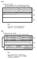
- FIG. 4 shows the content of the index partition and the data partition in an LTFS-formatted medium.
- FIG. 4 (A) shows information written to a tape medium immediately after the tape medium has been initialized using the LTFS format.
- the information shown in (A) is to be written to the tape medium immediately after the tape medium has been initialized using the LTFS format.
- FIG. 4 (B) shows information written to a tape medium when a file has been written after the tape medium has been initialized using the LTFS format.
- FIG. 4 (B) shows the data written to the tape medium when a file (File 1) is written after initialization of the tape medium using the LTFS format. The portion demarcated by the bold lines is added/updated data.
- Index#1 has metadata (index information) on File 1.
- the IP only holds an updated index.
- the DP holds the index history. The timing for updating the index is left to the implementation of the file system. Updates may be performed at fixed time intervals or may be updated only when a tape medium is removed from the tape drive. Even in the case of further continued use, the index positioned in the IP is always only the most recent index, and files and indices are appended to the DP without overwriting the existing indices.
- FIG. 4 (C) shows information written to a tape medium when another file has been written (File 2) following the state shown in (B).
- File 1 and File 2 are stored continuously on the tape medium.
- Index#2 has metadata (the index information) for File 1 and File 2.
- FIG. 4 (D) shows metadata written to a tape medium following the state shown in (B) when character information (File 1-2) has been appended to the end of File 1 and File 1 has been updated.
- a single file (File 1) is fragmented (dispersed) and recorded as File 1-1 and File 1-2.
- the reduction in the amount of free capacity in the tape medium at the time of the update depends on the amount of information.
- FIG. 5 shows the changed content of the index information when size-L File 1 has been partially rewritten.
- Extent elements include the number of the block (StartBlock) at the beginning of a file portion (data portion), the start offset (ByteOffset) inside the block of this number, the size of the data (ByteCount), and the file position in the data portion (FileOffset).
- User data is stored on the medium in record units of a size determined by the block size (for example, 512 KB).
- StartBlock indicates the order of blocks of a fixed size from the beginning of the tape medium.
- ByteOffset indicates the offset for the beginning of writing inside a block of a particular number.
- ByteCount indicates the data size of the data portion indicated by the extent.
- FileOffset indicates the file position in the data portion indicated by the extent.
- a block includes a record or Filemark (FM: record delimiter), and the size is indicated in the LTFS Label.
- the user data is recorded in the medium in record units of a size determined by the block size (for example, 512 KB).
- Extent (y) indicates the 250 KB data (record) in which 600 KB have been changed and written to a data portion of File 1.
- the data portions are not consecutive, so this is appended as a record of successive block numbers (StartBlock: N+4).
- D is the block size (for example, 512 KB).
- ByteOffset is the remainder of M+600 KB divided by D, and the offset is provided in block number N+2.
- the index of File 1 includes fragmented (dispersed) alignment information so that extent (x) ⁇ extent (y) ⁇ extent (z) due to the rewriting of data portions.
- the shaded area including the 250 KB of data is the needed data, and 600 KB of data is unneeded data.
- the example of the present invention is executed in the following steps.
- the automatic reclamation method proposed here uses three data partitions (DP1, DP2, DP3).
- a tape can be reused without having to completely interrupt the writing of data to the tape, by using a single drive, and without a user operation.
- the proposed method for moving data between data partitions includes more than simply deleting unneeded areas.
- the unneeded data is sent as zero values with the compression function enabled.
- the area used physically to write the data is reduced significantly and this increases the capacity.
- the data size is equal to or less than 10% of the original data size.
- the replacement data is zero.
- any other replacement data can be used as long as the data is highly compressible. In this method, the data itself can be replaced by highly compressible data without changing the size of the unneeded data.
- LTFS there is a single index partition (IP) in addition to the data partitions (DP). Because the index partition (IP) stores metadata (index information) on all of the files written to the data partitions (DP), the information on newly written areas has to be updated for all file information when data is moved (including the partition numbers, block numbers and block lengths).
- IP index partition
- the block numbers and the block lengths do not have to be changed.
- the index changes that have to be performed when data is moved between data partitions (DP) in the proposed method correspond only to the partition numbers indicated in the index.
- the content of all files in the partition have to be updated.
- FIG. 6 through FIG. 10 show an example of automatic reclamation in which files are written (and changed) normally in the three data partitions of the medium, and partial reclamation is performed.
- Partial reclamation refers to a process in which the file data in a data partition is divided into needed data and unneeded data, data is moved to another data partition, and storage areas are reused. When the writing of data to each data partition has been completed, partial reclamation is executed as the next step.
- FIG. 6 shows the first step (the normal writing of files) in the automatic reclamation method of the present invention.
- data writing starts with DP1.
- the writing of data to DP2 starts once the data in DP1 has reached a predetermined capacity and can no longer be written to the data partition.
- the gray portions are the areas with unneeded data.
- FIG. 7 shows the second step (partial reclamation) in the automatic reclamation method of the present invention.
- partial reclamation is performed by deleting the unneeded data in DP1 and moving the data to DP3.
- the gray portions and shaded portions of DP1 are storage areas that can be reused.
- the wavy line portions of DP3 indicates the needed data from the shaded portions of DP1 that has been moved.
- FIG. 8 shows the third step (the normal writing of files) in the automatic reclamation method of the present invention.
- the writing of data to the free space of DP3 starts once the data in DP2 has reached a predetermined capacity and can no longer be written to the data partition.
- the gray portions in DP2 indicate unneeded data, and the dotted portions indicate needed data.
- the dotted portions of DP3 indicate the continuation of new data writing.
- FIG. 9 shows the fourth step (partial reclamation) in the automatic reclamation method of the present invention.
- the unneeded data in DP1 is deleted and the data is moved to DP3.
- the dotted portions and shaded portions of DP2 are storage areas that can be reused.
- the meshed portions of DP1 indicates the needed data from the shaded portions of DP2 that has been moved.
- FIG. 10 shows the fifth and sixth steps (the normal writing of files) and the seventh step (partial reclamation) in the automatic reclamation method of the present invention.
- the normal writing in the fifth and sixth steps and the partial reclamation in the seventh step are repeated on each data partition.
- the continued writing in the fifth step is performed once the partial reclamation in the second step (2) has been performed, data has been written to the free space of DP3, and the predetermined capacity has been reached.
- FIG. 11 shows the method of copying data while switching between writing data from the host and performing reclamation.
- the gray arrows indicate the flow of data during normal file writing and file editing.
- the black arrows indicate the flow of data during partial reclamation in each data partition.
- the buffer 120 in the drive 60 is separate from the storage areas and can be used in separate reading and writing processes.
- the automatic reclamation is embodied by dividing an area of the drive buffer 120 into buffer B for normal reading and writing and buffer A for reclamation reading and writing. As shown in the drawing, normal reading and writing is performed by transferring data and writing the data to DP3 using the host 300 and the area in drive buffer B. The entire data copying method can be handled inside the drive. In partial reclamation, data is read to drive buffer A from the partition (DP1) when the predetermined tape capacity has been reached, and the data is written to a new partition (DP3).
- the method in the present example can switch between partial reclamation and normal reading and writing.
- LTFS is used to switch the processes performed by the drive.
- Capacity X is acquired from the drive for buffer A.
- the size of buffer B used in normal reading and writing does not require LTFS knowledge. Because the sizes of buffers A and B are determined at drive startup, the appropriate values may be determined beforehand with reference to the history of the system used by the LTFS.
- DP1 data may essentially be reclaimed at any time.
- the LTFS calculates the percentage of valid data in DP1 from the metadata and switches to reclamation mode when the percentage falls below a predetermined value. When a file has been edited many times, the percentage of unneeded data to needed data in the file increases and the valid data eventually falls below the predetermined value. If the predetermined value is 50%, then 50% of the tape capacity can be reused after reclamation. If the predetermined value is 90%, then 10% of the tape capacity can be reused after reclamation.
- the LTFS starts moving data in the manner described above. At this time, X amount of value data is read from DP1 to buffer A and then written to DP3. The valid data is identified from the index information in the LTFS. When valid data is discontinuous, X amount of data may be read from DP1 and written entirely to DP3. This is the most effective method for current tape drives.
- the LTFS When a normal reading and writing request is received by the LTFS from an application during reclamation, the LTFS gives priority to processing the request from the application. It switches from reclamation processing back into normal reading and writing mode.
- a check is performed on the timing used to write data to DP3. In the actual reclamation process, the timing used to interrupt reclamation does not have to take into account ease of implementation, and the completion time for the process is shortest on the SCSI command level.
- the timing for moving back to reclamation after normal reading and writing is usually triggered when the file processed by the application via the LTFS is closed.
- the switching also has to take into account the remaining capacity in DP2 which is closely monitored.
- Reclamation also has to be resumed when a file has been opened but a predetermined period of time has elapsed without any reading or writing occurring. It is theoretically possible to perform the reclamation process during reading and writing. However, it takes time to read and write data to an actual tape drive. Therefore, when reclamation is to be completed in a fixed time period, the normal reading and writing operation should be properly allocated, and the reclamation operation should be performed separately on a certain timing.
- FIG. 12 is a flowchart showing the completion of automatic reclamation while switching between normal reading and writing operations and reclamation operations.
- Capacity X for buffer A is obtained from the drive buffer 120 for reclamation.
- capacity Y for buffer B is obtained from the drive buffer 120 for normal reading and writing.
- the file system uses buffer B to write and edit files in DP1.
- the data writing process continues on the open files ( 1110 ). If NO, the partial reclamation process ( 1114 ) is started.
- FIG. 13 shows a situation in which a file including unneeded data (unneeded blocks) is compressed and reclaimed.
- FIG. 13 ( a ) is a conceptual diagram showing how the needed data for a file is compressed and reclaimed along with the unneeded data (unneeded blocks).
- This method is used during the copying performed in the partial reclamation steps, which are the second step ( FIG. 7 ), the fourth step ( FIG. 9 ), the seventh step ( FIG. 10 ), the process in ( 1114 ) and the process in ( 1116 ) ( FIG. 12 ).
- blocks 2, 3, 5 and 7 (b2, b3, b5, b7) contain unneeded data.
- the values in these blocks are changed to zero to accomplish an effective compression function, and the data is written to DP3.
- areas with a data size equivalent to the block numbers in DP1 are used in DP3.
- the data is copied to the other data partition after replacing the data in the blocks to be deleted with zeroes in order to increase the compression rate.
- the unneeded data can be compressed to 10% of the original size or less, the reclamation is not insignificant even though the unneeded data remains in the tape area in compressed format. Because the unneeded blocks remain but are replaced by zeroes, there are no positional discrepancies between blocks of needed data in files that have been edited several times. This is advantageous because the time required to recalculate the extents can be eliminated.
- the information indicating the location of files includes the following. This information needs to at least include the number of files.
- the index (metadata) for a file includes a data partition ID along with the extents (start block number, block length).
- the information for File A, File B and File C can be established as follows.
- the partition ID is not a pointer to a physical partition on the tape.
- the metadata for LTFS is divided into a label portion indicating information for the entire tape, and an index portion including all of the individual file directory information.
- the information in the table below is a portion of an index including information on each file.
- the partition information in the index is linked to an actual partition number on a tape and a label.
- partition IDs for file data on data partitions DP1, DP2 and DP3 (referred to below simply as partition IDs) are recorded in the index partition using the following values.
- the label information (partition IDs) for each data partition DP1, DP2, DP3 has been assigned as follows:
- the index includes the partition ID for the partition on which each file is stored.
- the method of the present invention can complete the partial reclamation process without having to completely interrupt the writing of data to the tape. This enables a tape to be reused using a single drive, and without a user operation.
- the method of the present invention can provide two data partitions and perform automatic reclamation on the data in one of the data partitions.
- the present invention is also not limited in terms of the number of partitions on the medium and is not limited to a file system (LTFS).
- LTFS file system
- four or more data partitions can be used by a writing application or the write control driver in the tape drive.
- the present invention was explained above using an embodiment (example), but the technical scope of the present invention is not limited in any way to the embodiment. It should be clear to a person of skill in the art that various modifications and substitutions can be made without departing from the spirit and scope of the present invention.
Abstract
Description
-
- FID (Format Identification Dataset) is special data written at the beginning of the tape medium when the tape drive initializes the tape medium, and includes information such as the number of partitions in the tape medium and the capacity of each partition.
- VOL1Label, also called the ANSI Label, is a general format label literally defined by ANSI.
- LTFSLabel is a label stipulated by the LTFS format, and holds information indicating which version of the LTFS format was used to format the tape medium. The size of the records recorded on the medium is indicated here. The record size is also known as the block size. The record size is ensured even when the end of the file is less than the block size (for example, 512 KB).
- FM (Filemarks) are commonly used in tape media. These are used to specify the head of data (seek), and function similar to bookmarks.
-
Index # 0 is the index written during formatting. At this stage, it does not include file-specific information because no files are present, but rather holds information such as the volume name of the tape medium.
-
- Data writing starts with DP1.
- When the data written to DP1 reaches the predetermined capacity, writing to DP1 is stopped. Data writing then starts in DP2.
- Data in DP1 is moved to DP3 after the unneeded areas have been deleted. Because the unneeded areas have been deleted, the data in DP3 does not reach the predetermined capacity. Because writing to DP2 cannot be performed at the same time, the LTFS controls the process so that data is written normally to DP2 and then data is copied to DP3. When the data has been moved from DP1 to DP3, the data areas in DP1 can be reused.
- When the data written to DP2 reaches the predetermined capacity, writing is stopped. Data writing then starts in the free space of DP3.
5. Data in DP2 is moved to DP1 after the unneeded areas have been deleted.
(1106): When DP1 writing has been completed, the LTFS enters partial reclamation mode. Reclamation is initiated on the timing explained above in (B).
(1108): It is determined whether or not there are any open files. The LTFS determines whether or not there are any files being written or edited. If YES, the data writing process continues on the open files (1110). If NO, the partial reclamation process (1114) is started.
(1110): The writing of data for an open file is continued to DB2 via buffer B.
(1112): It is determined whether or not the amount of data written to DP2 exceeds a predetermined value in order to set the timing for the partial reclamation of file data in DP1. More specifically, the timing used is the one explained in (D) above. The partial reclamation timing is determined so as to take into account the progress in the normal writing. When the normal writing capacity for DP2 has been exceeded, reclamation is started. If the determination is YES, partial reclamation (1114) is started via buffer A. If NO, the writing of open file data continues (1108).
(1114): During partial reclamation, X amount of valid data is read from DP1 to buffer A. If the determination in (1110) is YES, the writing of open file data continues. This data does not include unneeded data arising from file data editing. In order to delete unneeded data, the extent is reset so that the block numbers of the unneeded data are deleted. In order to avoid resetting an extent, the unneeded data is replaced by highly compressed data as explained below, and the unneeded data sections are copied along with the other data. If the determination in (1114) is NO, the valid data (needed data) is written to buffer A and stored.
(1116): During partial reclamation, data is written from buffer A to DP3.
(1118): During partial reclamation, it is determined whether the end of the data read from DP1 has been reached. The end of reclamation of data in DP1 is then determined. If YES, the index is changed (1120). If NO, the system continues to verify whether there is an open file during the writing process (1108).
(1120): When the partial reclamation is ended, the index for the copied files is changed. When the valid data includes needed data and unneeded data, only the data partition ID in the file index is changed. The extents (block numbers, offsets, sizes) do not have to be changed. When the valid data that has been copied only contains needed data, calculating the extents to delete blocks in the unneeded data sections takes time. When the partial reclamation has been completed, the storage area in DP1 occupied by the needed data and the unneeded data in DP1 is released.
(1122): The partition to be checked is changed from data partition DP1 to data partition DP2. The process switches to partial reclamation mode for the file data stored in DP2. Returning to (1102), normal writing continues to DP2 in order to fill the free storage space in DP2 with data. At the same time, the processing steps for partial reclamation of data stored in DP2 are performed in DP1. When partial reclamation of file data in DP2 has been completed, the partition to be checked is changed from DP2 to DP3 (1122). Partial reclamation is then performed on DP3.
4. Copying Deleted Data Compressed Using Zero Values:
-
- File A includes, as the index, data partition ID=a and an extent (start block number=0, block length=5).
- File B includes, as the index, data partition ID=a and an extent (start block number=5, block length=20).
- File C includes, as the index, data partition ID=a and an extent (start block number=25, block length=20).
-
- File A includes, as the index, data partition ID=c and an extent (start block number=0, block length=5).
- File B remains on the tape but the allocation of an extent and a partition ID has been disregarded in the index.
- File C includes, as the index, data partition ID=c and an extent (start block number=25, block length=20).
-
- 40: Tape cartridge (medium, tape)
- 60: Tape drive
- 110: Communication interface (I/F)
- 120: Buffer (drive buffer)
- 130: Recording channel
- 140: Read/write head
- 150: Control unit (controller, includes read/write control)
- 160: Positioning unit
- 170: Motor driver
- 180: Motor
- 300: Host (file system, includes applications)
Claims (8)
Applications Claiming Priority (2)
| Application Number | Priority Date | Filing Date | Title |
|---|---|---|---|
| JP2013243395A JP6341652B2 (en) | 2013-11-25 | 2013-11-25 | Automatic reclamation of tape cartridge data |
| JP2013-243395 | 2013-11-25 |
Publications (2)
| Publication Number | Publication Date |
|---|---|
| US20150146317A1 US20150146317A1 (en) | 2015-05-28 |
| US9236065B2 true US9236065B2 (en) | 2016-01-12 |
Family
ID=53182482
Family Applications (1)
| Application Number | Title | Priority Date | Filing Date |
|---|---|---|---|
| US14/511,660 Expired - Fee Related US9236065B2 (en) | 2013-11-25 | 2014-10-10 | Reclamation of data on tape cartridge |
Country Status (2)
| Country | Link |
|---|---|
| US (1) | US9236065B2 (en) |
| JP (1) | JP6341652B2 (en) |
Families Citing this family (5)
| Publication number | Priority date | Publication date | Assignee | Title |
|---|---|---|---|---|
| US9996459B2 (en) | 2015-09-21 | 2018-06-12 | International Business Machines Corporation | Reclaiming of sequential storage medium |
| US10089481B2 (en) | 2015-09-23 | 2018-10-02 | International Business Machines Corporation | Securing recorded data |
| US11221989B2 (en) * | 2018-07-31 | 2022-01-11 | International Business Machines Corporation | Tape image reclaim in hierarchical storage systems |
| US10824338B2 (en) * | 2018-11-02 | 2020-11-03 | EMC IP Holding Company LLC | Using variable sized uncompressed data blocks to address file positions when simultaneously compressing multiple blocks |
| JPWO2022185650A1 (en) * | 2021-03-01 | 2022-09-09 |
Citations (2)
| Publication number | Priority date | Publication date | Assignee | Title |
|---|---|---|---|---|
| US20080243860A1 (en) | 2007-03-26 | 2008-10-02 | David Maxwell Cannon | Sequential Media Reclamation and Replication |
| US8966169B2 (en) * | 2009-12-25 | 2015-02-24 | International Business Machines Corporation | Linear recording device for executing optimum writing upon receipt of series of commands including mixed read and write commands and a method for executing the same |
Family Cites Families (1)
| Publication number | Priority date | Publication date | Assignee | Title |
|---|---|---|---|---|
| JP2012243339A (en) * | 2011-05-17 | 2012-12-10 | Nec Corp | Magnetic tape unit, data rearrangement method for magnetic tape and its program |
-
2013
- 2013-11-25 JP JP2013243395A patent/JP6341652B2/en not_active Expired - Fee Related
-
2014
- 2014-10-10 US US14/511,660 patent/US9236065B2/en not_active Expired - Fee Related
Patent Citations (4)
| Publication number | Priority date | Publication date | Assignee | Title |
|---|---|---|---|---|
| US20080243860A1 (en) | 2007-03-26 | 2008-10-02 | David Maxwell Cannon | Sequential Media Reclamation and Replication |
| WO2008116751A1 (en) | 2007-03-26 | 2008-10-02 | International Business Machines Corporation | Improved sequential media reclamation and replication |
| US8738588B2 (en) | 2007-03-26 | 2014-05-27 | International Business Machines Corporation | Sequential media reclamation and replication |
| US8966169B2 (en) * | 2009-12-25 | 2015-02-24 | International Business Machines Corporation | Linear recording device for executing optimum writing upon receipt of series of commands including mixed read and write commands and a method for executing the same |
Also Published As
| Publication number | Publication date |
|---|---|
| JP6341652B2 (en) | 2018-06-13 |
| US20150146317A1 (en) | 2015-05-28 |
| JP2015103033A (en) | 2015-06-04 |
Similar Documents
| Publication | Publication Date | Title |
|---|---|---|
| US10915244B2 (en) | Reading and writing via file system for tape recording system | |
| JP6041839B2 (en) | Method, program and tape recording system for storing meta information | |
| JP5623239B2 (en) | Storage device for eliminating duplication of write record, and write method thereof | |
| US9236065B2 (en) | Reclamation of data on tape cartridge | |
| JP6124734B2 (en) | How to write files to tape media that can be read at high speed | |
| US20140379980A1 (en) | Selective duplication of tape cartridge contents | |
| JP5925280B2 (en) | Method, program, and tape device for erasing files written on tape | |
| US9098210B2 (en) | Automatically linking partitions on a tape media device | |
| US9471255B2 (en) | Tape storage device and writing method therefor | |
| JP6005122B2 (en) | How to span and write files to multiple tape cartridges | |
| US20150095566A1 (en) | Reading Speed of Updated File by Tape Drive File System | |
| US9058843B2 (en) | Recovery of data written before initialization of format in tape media | |
| US10656853B2 (en) | Tape having multiple data areas |
Legal Events
| Date | Code | Title | Description |
|---|---|---|---|
| AS | Assignment |
Owner name: INTERNATIONAL BUSINESS MACHINES CORPORATION, NEW Y Free format text: ASSIGNMENT OF ASSIGNORS INTEREST;ASSIGNORS:ABE, ATSUSHI;OHTA, YUMIKO;MASUDA, SETSUKO;AND OTHERS;SIGNING DATES FROM 20140930 TO 20141006;REEL/FRAME:033930/0611 |
|
| STCF | Information on status: patent grant |
Free format text: PATENTED CASE |
|
| FEPP | Fee payment procedure |
Free format text: MAINTENANCE FEE REMINDER MAILED (ORIGINAL EVENT CODE: REM.); ENTITY STATUS OF PATENT OWNER: LARGE ENTITY |
|
| LAPS | Lapse for failure to pay maintenance fees |
Free format text: PATENT EXPIRED FOR FAILURE TO PAY MAINTENANCE FEES (ORIGINAL EVENT CODE: EXP.); ENTITY STATUS OF PATENT OWNER: LARGE ENTITY |
|
| STCH | Information on status: patent discontinuation |
Free format text: PATENT EXPIRED DUE TO NONPAYMENT OF MAINTENANCE FEES UNDER 37 CFR 1.362 |
|
| FP | Expired due to failure to pay maintenance fee |
Effective date: 20200112 |