US9236033B2 - Color processing apparatus and color processing method - Google Patents
Color processing apparatus and color processing method Download PDFInfo
- Publication number
- US9236033B2 US9236033B2 US13/866,868 US201313866868A US9236033B2 US 9236033 B2 US9236033 B2 US 9236033B2 US 201313866868 A US201313866868 A US 201313866868A US 9236033 B2 US9236033 B2 US 9236033B2
- Authority
- US
- United States
- Prior art keywords
- color
- adjusted
- candidate
- range
- colors
- Prior art date
- Legal status (The legal status is an assumption and is not a legal conclusion. Google has not performed a legal analysis and makes no representation as to the accuracy of the status listed.)
- Expired - Fee Related, expires
Links
- 238000012545 processing Methods 0.000 title claims description 46
- 238000003672 processing method Methods 0.000 title claims description 7
- 239000003086 colorant Substances 0.000 claims abstract description 119
- 230000000007 visual effect Effects 0.000 claims description 31
- 238000000034 method Methods 0.000 claims description 25
- 230000006870 function Effects 0.000 description 30
- 230000003595 spectral effect Effects 0.000 description 15
- 238000010586 diagram Methods 0.000 description 12
- 238000005259 measurement Methods 0.000 description 11
- 230000008569 process Effects 0.000 description 5
- 208000016709 aortopulmonary window Diseases 0.000 description 4
- 230000008859 change Effects 0.000 description 3
- 238000002474 experimental method Methods 0.000 description 3
- 238000006243 chemical reaction Methods 0.000 description 2
- 230000000694 effects Effects 0.000 description 2
- 230000007613 environmental effect Effects 0.000 description 2
- 230000014509 gene expression Effects 0.000 description 2
- 238000012986 modification Methods 0.000 description 2
- 230000004048 modification Effects 0.000 description 2
- 230000035945 sensitivity Effects 0.000 description 2
- 230000008901 benefit Effects 0.000 description 1
- 238000012937 correction Methods 0.000 description 1
- 230000002708 enhancing effect Effects 0.000 description 1
- 239000011159 matrix material Substances 0.000 description 1
- 230000003287 optical effect Effects 0.000 description 1
Images


Classifications
-
- G—PHYSICS
- G09—EDUCATION; CRYPTOGRAPHY; DISPLAY; ADVERTISING; SEALS
- G09G—ARRANGEMENTS OR CIRCUITS FOR CONTROL OF INDICATING DEVICES USING STATIC MEANS TO PRESENT VARIABLE INFORMATION
- G09G5/00—Control arrangements or circuits for visual indicators common to cathode-ray tube indicators and other visual indicators
- G09G5/22—Control arrangements or circuits for visual indicators common to cathode-ray tube indicators and other visual indicators characterised by the display of characters or indicia using display control signals derived from coded signals representing the characters or indicia, e.g. with a character-code memory
- G09G5/30—Control of display attribute
-
- G—PHYSICS
- G01—MEASURING; TESTING
- G01J—MEASUREMENT OF INTENSITY, VELOCITY, SPECTRAL CONTENT, POLARISATION, PHASE OR PULSE CHARACTERISTICS OF INFRARED, VISIBLE OR ULTRAVIOLET LIGHT; COLORIMETRY; RADIATION PYROMETRY
- G01J3/00—Spectrometry; Spectrophotometry; Monochromators; Measuring colours
- G01J3/46—Measurement of colour; Colour measuring devices, e.g. colorimeters
- G01J3/462—Computing operations in or between colour spaces; Colour management systems
-
- G—PHYSICS
- G01—MEASURING; TESTING
- G01J—MEASUREMENT OF INTENSITY, VELOCITY, SPECTRAL CONTENT, POLARISATION, PHASE OR PULSE CHARACTERISTICS OF INFRARED, VISIBLE OR ULTRAVIOLET LIGHT; COLORIMETRY; RADIATION PYROMETRY
- G01J3/00—Spectrometry; Spectrophotometry; Monochromators; Measuring colours
- G01J3/46—Measurement of colour; Colour measuring devices, e.g. colorimeters
- G01J3/463—Colour matching
-
- G—PHYSICS
- G09—EDUCATION; CRYPTOGRAPHY; DISPLAY; ADVERTISING; SEALS
- G09G—ARRANGEMENTS OR CIRCUITS FOR CONTROL OF INDICATING DEVICES USING STATIC MEANS TO PRESENT VARIABLE INFORMATION
- G09G3/00—Control arrangements or circuits, of interest only in connection with visual indicators other than cathode-ray tubes
- G09G3/20—Control arrangements or circuits, of interest only in connection with visual indicators other than cathode-ray tubes for presentation of an assembly of a number of characters, e.g. a page, by composing the assembly by combination of individual elements arranged in a matrix no fixed position being assigned to or needed to be assigned to the individual characters or partial characters
- G09G3/2003—Display of colours
-
- H—ELECTRICITY
- H04—ELECTRIC COMMUNICATION TECHNIQUE
- H04N—PICTORIAL COMMUNICATION, e.g. TELEVISION
- H04N9/00—Details of colour television systems
- H04N9/64—Circuits for processing colour signals
-
- G—PHYSICS
- G09—EDUCATION; CRYPTOGRAPHY; DISPLAY; ADVERTISING; SEALS
- G09G—ARRANGEMENTS OR CIRCUITS FOR CONTROL OF INDICATING DEVICES USING STATIC MEANS TO PRESENT VARIABLE INFORMATION
- G09G2320/00—Control of display operating conditions
- G09G2320/02—Improving the quality of display appearance
- G09G2320/028—Improving the quality of display appearance by changing the viewing angle properties, e.g. widening the viewing angle, adapting the viewing angle to the view direction
-
- G—PHYSICS
- G09—EDUCATION; CRYPTOGRAPHY; DISPLAY; ADVERTISING; SEALS
- G09G—ARRANGEMENTS OR CIRCUITS FOR CONTROL OF INDICATING DEVICES USING STATIC MEANS TO PRESENT VARIABLE INFORMATION
- G09G2320/00—Control of display operating conditions
- G09G2320/06—Adjustment of display parameters
- G09G2320/0606—Manual adjustment
-
- G—PHYSICS
- G09—EDUCATION; CRYPTOGRAPHY; DISPLAY; ADVERTISING; SEALS
- G09G—ARRANGEMENTS OR CIRCUITS FOR CONTROL OF INDICATING DEVICES USING STATIC MEANS TO PRESENT VARIABLE INFORMATION
- G09G2320/00—Control of display operating conditions
- G09G2320/06—Adjustment of display parameters
- G09G2320/0666—Adjustment of display parameters for control of colour parameters, e.g. colour temperature
-
- G—PHYSICS
- G09—EDUCATION; CRYPTOGRAPHY; DISPLAY; ADVERTISING; SEALS
- G09G—ARRANGEMENTS OR CIRCUITS FOR CONTROL OF INDICATING DEVICES USING STATIC MEANS TO PRESENT VARIABLE INFORMATION
- G09G2320/00—Control of display operating conditions
- G09G2320/06—Adjustment of display parameters
- G09G2320/0693—Calibration of display systems
-
- G—PHYSICS
- G09—EDUCATION; CRYPTOGRAPHY; DISPLAY; ADVERTISING; SEALS
- G09G—ARRANGEMENTS OR CIRCUITS FOR CONTROL OF INDICATING DEVICES USING STATIC MEANS TO PRESENT VARIABLE INFORMATION
- G09G2354/00—Aspects of interface with display user
Definitions
- the present invention relates to a color processing apparatus and color processing method and, more particularly, to a color processing apparatus and color processing method required for color adjustment of a display device.
- Japanese Patent Laid-Open No. 2006-203622 discloses a color adjustment technique including a color matching operation. That is, color matching properties are stored based on user's color matching experiments, and a color matching property corresponding to user identification information is selected to execute color conversion.
- Literature 2 describes a method of selecting a color patch of a desired color from a plurality of color patches, and conducting color adjustment in addition to the aforementioned color adjustment method.
- the method of selecting a color patch from a plurality of color patch allows the user to select a color patch close to a desired color from presented color patches, but the user cannot often select the desired color itself.
- the user in order to obtain a desired color adjustment result, the user has to adjust parameters such as RGB values and hue, lightness, and saturation values, thus posing the same problem as above.
- a color processing apparatus for performing an adjustment of display color of a display device, the apparatus comprising: a display controller configured to display, on the display device, a target color to be adjusted, which can be designated by a user, and a plurality of candidate colors that may be selected by a user in preference to the target color, which candidate colors define a first color range including the target color to be adjusted; and a selector configured to select one of the plurality of candidate colors based on a user instruction, wherein the display controller displays, subsequent to selection of one of the candidate colors, on the display device a further plurality of candidate colors which define a second color range including the selected candidate color as a second target color to be adjusted, and wherein the second color range is narrower than the first color range.
- FIG. 1 is a block diagram showing the arrangement of a color processing apparatus according to the first embodiment.
- FIG. 2 is a view showing an example of an AP window (GUI).
- GUI AP window
- FIGS. 3A and 3B are views showing examples of other GUIs.
- FIG. 4 is a block diagram for explaining the functional arrangement of color processing associated with color adjustment.
- FIG. 5 is a flowchart for explaining color processing executed by a display controller.
- FIGS. 6A and 6B are views showing positions of a candidate colors on an a*b* space.
- FIG. 7 is a block diagram showing the arrangement of a color processing apparatus according to the second embodiment.
- FIG. 8 is a block diagram for explaining the functional arrangement of color processing associated with color adjustment according to the second embodiment.
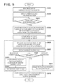
- FIG. 9 is a flowchart for explaining color processing according to the second embodiment.
- FIG. 10 shows representative color matching functions.
- FIG. 11 is a block diagram for explaining the functional arrangement of color processing associated with color adjustment according to the third embodiment.
- FIG. 12 is a flowchart for explaining color processing according to the third embodiment.
- FIG. 13 is a view showing an example of an initial color to be adjusted (central point P of adjustment) and initial values of color ranges.
- FIG. 14 shows color matching functions according to viewing angles.
- FIG. 15 is a block diagram for explaining the functional arrangement of color processing associated with color adjustment according to the fourth embodiment.
- FIG. 16 is a flowchart for explaining color processing according to the fourth embodiment.
- FIG. 17 is a view showing an example of a GUI according to the fourth embodiment.
- FIG. 18 is a view showing a distribution of chromaticity values a* and b*, which reflect personal differences of visual characteristics and viewing angles to a measurement value of a color to be adjusted.
- a microprocessor (CPU) 201 executes programs stored in a read only memory (ROM) 209 and a hard disk drive (HDD) 203 using a main memory 202 such as a random access memory (RAM) as a work memory, and controls units to be described later through a system bus 206 .
- ROM read only memory
- HDD hard disk drive
- main memory 202 such as a random access memory (RAM) as a work memory
- An instruction input unit 207 such as a keyboard and mouse, and an external storage device 208 , such as a USB memory, memory card, optical disk drive, or hard disk drive, are connected to a general-purpose interface (I/F) 204 , such as USB (Universal Serial Bus) or IEEE1394.
- I/F general-purpose interface
- a monitor 205 as a display device connected to a video card (VC) 210 which provides an interface such as HDMI (High-Definition Multimedia Interface) displays a user interface (UI) and information indicating intermediate processing results and processing results under the control of the CPU 201 .
- VC video card
- UI user interface
- the CPU 201 loads an application program (AP) stored in the ROM 209 , HDD 203 , or external storage device 208 onto a predetermined area of the main memory 202 in accordance with a user instruction input via the instruction input unit 207 . Then, the CPU 201 executes the AP, and displays the UI on the monitor 205 according to the AP.
- AP application program
- the CPU 201 loads various data stored in the HDD 203 or external storage device 208 onto a predetermined area of the main memory 202 according to a user operation on the UI. Then, the CPU 201 applies predetermined calculation processing to the data loaded on the main memory 202 according to the AP. Then, the CPU 201 displays the calculation processing result on the monitor 205 or stores the calculation processing result in the HDD 203 or external storage device 208 according to a user operation on the UI.
- the CPU 201 can also exchange programs, data, and calculation processing results with a server apparatus on a network via a network I/F (not shown) connected to the system bus 206 .
- a network I/F not shown
- the CPU 201 can download programs and various data from a specific homepage and can acquire them in the form of attached files to e-mail messages.
- GUI graphical user interface
- FIG. 2 shows an example of the AP window (GUI).
- GUI AP window
- candidate colors BT 1 to BT 4 used to adjust display colors on the monitor 205 are arranged on a candidate section 301 of the AP window.
- the selected color (to be referred to as a “color to be adjusted” hereinafter) is displayed on a selected color window 302 , and candidate colors BT 1 to BT 4 close to the color to be adjusted are arranged on the candidate section 301 .
- the user selects the color to be adjusted, he or she can adjust the color to be adjusted to a desired display color by selecting or repetitively selecting the color arranged on the candidate section 301 .
- the user presses a “back” button or adjusts relative distances ⁇ a* and ⁇ b* of colors between candidate colors using text boxes 304 and 305 so as to change candidate color ranges. Also, the user can adjust the distances ⁇ a* and ⁇ b* by operating spin buttons 306 and 307 displayed beside the text boxes 304 and 305 . That is, the text boxes 304 and 305 and spin buttons 306 and 307 function as an input section which allows the user to input chromaticity ranges.
- the user repeats selection of the candidate color and adjustment of the distances ⁇ a* and ⁇ b* until a desired color is displayed on the selected color window 302 .
- the desired color is displayed on the selected color window 302 .
- the GUI shown in FIG. 2 is an example, and any other GUIs may be used as long as the candidate colors can be displayed and selected, the selected color can be displayed, and the distances ⁇ a* and ⁇ b* can be adjusted.
- FIGS. 3A and 3B show other examples of GUIs.
- FIG. 3A shows a GUI on which candidate colors are arranged in four directions to have the selected color window 302 as the center. That is, if chromaticity values of the selected color are (a 0 , b 0 ), this GUI has a relationship of a color (a 0 + ⁇ a, b 0 ) in a red direction, a color (a 0 , b 0 + ⁇ b) in a yellow direction, a color (a 0 ⁇ a, b 0 ) in a green direction, and a color (a 0 , b 0 ⁇ b) in a blue direction. Also, the GUI shown in FIG.
- 3B has a relationship of a color (a 0 + ⁇ a, b 0 + ⁇ b) in an orange direction, a color (a 0 ⁇ a, b 0 + ⁇ b) in a greenish yellow direction, a color (a 0 ⁇ a, b 0 ⁇ b) in a cyan direction, and a color (a 0 + ⁇ a, b 0 ⁇ b) in a violet direction.
- a layout of candidate colors as a combination of FIGS. 3A and 3B is available.
- a display controller 102 displays candidate colors to be adjusted expressed by input image data on the GUI shown in FIG. 2 or FIG. 3A or 3 B.
- the user designates a display color of the monitor 205 as a color to be adjusted by operating a selector 101 configured by the GUI and instruction input unit 207 , inputs selection information of the color displayed on the GUI, and changes values of color ranges.
- the display controller 102 executes processing to be described below based on the designated color to be adjusted, input selection information, changed values of the color ranges, and button operation (to be referred to as a “user input” hereinafter).
- the color processing executed by the display controller 102 will be described below with reference to the flowchart shown in FIG. 5 . Note that a case will be described below wherein there are a plurality of candidate colors to be adjusted. However, when there is only one candidate color to be adjusted, the processing starts from step S 604 .
- the display controller 102 inputs image data (for example, sRGB values) of candidate colors to be adjusted, which are stored in the main memory 202 , HDD 203 , or external storage device 208 (S 601 ), and displays the candidate colors to be adjusted on the GUI (S 602 ). Then, the display controller 102 waits for a user input (selection of a color to be adjusted) (S 603 ). Note that when the monitor 205 is not an sRGB monitor, the display controller 102 executes color processing for converting sRGB values into device RGB values of the monitor.
- image data for example, sRGB values
- the display controller 102 converts image data of the color to be adjusted into color values on a device-independent color space, and sets the obtained color values as central values P(L 0 , a 0 , b 0 ) of color adjustment (S 604 ).
- the image data is given by sRGB values of 8 bits per color
- the device-independent color space is a CIELab space
- the image data is converted into color values by:
- R′ R/255
- Xn, Yn, and Zn are X, Y, and Z values of a white point of the monitor 205 .
- Expressions (1) represent the conversion example of sRGB values into CIEXYZ values. However, when image data is given by other device RGB values, a gamma value ⁇ and matrix coefficients according to the color characteristic of that device can be set. Of course, using a three-dimensional lookup table (3DLUT) and interpolation calculations corresponding to the calculations described by expressions (1), sRGB values may be converted into XYZ values and Lab values.
- 3DLUT three-dimensional lookup table
- the display controller 102 acquires initial values ⁇ a and ⁇ b of color ranges ⁇ a* and ⁇ b* (S 605 ), and sets color values of candidate colors based on the central values (L 0 , a 0 , b 0 ) of color adjustment and the values of the color ranges (S 606 ).
- BT 1 ( L 0 ,a 0 + ⁇ a,b 0 + ⁇ b );
- BT 2 ( L 0 ,a 0 + ⁇ a,b 0 ⁇ b );
- BT 3 ( L 0 ,a 0 ⁇ a,b 0 ⁇ b );
- BT 4 ( L 0 ,a 0 ⁇ a,b 0 + ⁇ b );
- FIGS. 6A and 6B show positions of the candidate colors on an a*b* space.
- the display controller 102 displays four colors corresponding to vertices of a rectangle of a color range on the GUI as candidate colors (S 607 ).
- the display controller 102 converts color values of the candidate colors into XYZ values, and further converts the XYZ values into device RGB values of the monitor 205 .
- the display controller 102 waits for a user input (S 608 ). If a candidate color is selected by the user input, the display controller 102 updates the central values P of color adjustment by the color values of the selected candidate color (S 609 ). Note that to prepare for a case in which the user presses the “back” button, the central values P, the color values of the candidate colors, and the like are backed up to a predetermined area on the main memory 202 . For example, when the user selects the candidate color BT 1 , the central values P are updated as follows. P ( L 0 ,a 0 ,b 0) ⁇ P ( L 0 ,a 0 + ⁇ a,b 0 + ⁇ b ) (3)
- step S 606 the process returns to step S 606 .
- the display controller 102 updates the color values of the candidate colors by the updated central values P of color adjustment and the changed color ranges ⁇ a and ⁇ b (S 606 ), and re-displays the updated color to be adjusted and candidate colors (S 607 ).
- BT 1 ⁇ L 0 ,a 0+(1 +k ) ⁇ a,b 0+(1 +k ′) ⁇ b ⁇ ;
- BT 2 ⁇ L 0 ,a 0+(1 +k ) ⁇ a,b 0 ⁇ (1 +k ′) ⁇ b ⁇ ;
- BT 3 ⁇ L 0 ,a 0 ⁇ (1 +k ) ⁇ a,b 0 ⁇ (1 +k ′) ⁇ b ⁇ ;
- BT 4 ⁇ L 0 ,a 0 ⁇ (1 +k ) ⁇ a,b 0+(1 +k ′) ⁇ b ⁇ ;
- the display controller 102 displays the updated central values P and colors corresponding to four points of the colors to be adjusted as new candidate colors on the GUI (S 607 ). That is, an area bounded by the new candidate colors is narrower than that bounded by the candidate colors shown in FIG. 6A , since the color ranges are multiplied by the coefficients k and k′.
- step S 608 the display controller 102 changes the values of the color ranges to instructed values (S 611 ), and the process returns to step S 606 . That is, the display controller 102 updates color values of candidate colors by the central values P of color adjustment and the changed color ranges ⁇ a and ⁇ b (S 606 ), and re-displays updated candidate colors (S 607 ).
- the display controller 102 stores the central value P of color adjustment as a display color (Lab values) corresponding to the color to be adjusted (for example, sRGB values) in a predetermined area of the HDD 203 or external storage device 208 (S 612 ), thus ending the processing.
- a display color for example, sRGB values
- the relationship between the color to be adjusted (for example, sRGB values) and corresponding display color (Lab values) is stored in a table associated with the monitor 205 .
- Data of that table are reflected as those of grid points of, for example, a 3DLUT used in color processing upon displaying an image on the monitor 205 , and when image data corresponding to the color to be adjusted is input, the corresponding display color is displayed on the monitor 205 .
- one color is selected from a plurality of candidate colors corresponding to a color to be adjusted, and a plurality of candidate colors are displayed to have the selected color as a color to be adjusted.
- the color range of candidate colors is narrowed down every time the candidate color is selected. Therefore, when the user repetitively selects a color close to a desired color, the color range is gradually narrowed down, and a desired display color corresponding to the color to be adjusted can be finally set.
- every time the candidate color is selected colors of candidate colors become closer to each other, and the user can strictly compare color differences, thus enhancing the setting precision of the desired display color.
- the color adjustment is attained by only display on the monitor.
- the color adjustment can also be done while comparing a color displayed by another monitor or projector or that of a printed matter with a display color on the GUI, thus obtaining the same effects.
- the first embodiment has exemplified the case in which a color to be adjusted is selected from candidate colors to be adjusted displayed on the monitor 205 .
- the second embodiment will exemplify a case in which a color of an adjustment target is acquired and is set as a color to be adjusted.
- the color of the adjustment target includes that of a printed matter (that of a printer), that displayed by a device such as a monitor or projector, or that of various articles and objects.
- a measuring device 211 is connected to a general-purpose I/F 204 .
- the measuring device 211 an illuminometer, RGB sensor, spectral radiance meter, digital camera, and the like can be used.
- the measuring device 211 Upon reception of a measurement instruction of a CPU 201 , the measuring device 211 measures a color of an adjustment target, and inputs colorimetric values (device RGB values, CIELab values, or CIEXYZ values) of that color to the color processing apparatus.
- the functional arrangement of color processing associated with color adjustment according to the second embodiment will be described below with reference to the block diagram shown in FIG. 8 .
- Note that the arrangement shown in FIG. 8 is implemented when a CPU 201 executes a color adjustment AP.
- the functional arrangement of the second embodiment includes a color acquisition unit 103 which acquires colorimetric values in addition to that shown in FIG. 4 .
- the color acquisition unit 103 controls the measuring device 211 to acquire colorimetric values of a color of an adjustment target (S 621 ).
- a display controller 102 sets central values P of color adjustment to have the acquired colorimetric values as an initial color to be adjusted (S 622 ). Note that when colorimetric values are device RGB values or XYZ values, the display controller 102 converts the colorimetric values into Lab values.
- the subsequent processes are the same as those in step S 605 and subsequent steps shown in FIG. 5 , and a detailed description thereof will not be repeated.
- the initial color to be adjusted is set based on the colorimetric values obtained by measuring the color of the adjustment target. For this reason, by setting the initial color to be adjusted in consideration of type of a device, article, or object as an adjustment target and the influence of environmental light, the load on the user who sets the initial color to be adjusted can be reduced.
- color adjustment may be done by only a display on the monitor.
- a display color closer to the color of the adjustment target can be set.
- the third embodiment will exemplify a case in which candidate colors are displayed by setting color ranges using information indicating personal differences of visual characteristics.
- an HDD 203 or external storage device 208 stores personal color matching functions, that is, values which express visual sensitivities of persons with respect to light wavelengths.
- FIG. 10 shows representative color matching functions for four persons. Such data can be acquired by conducting color matching experiments for a plurality of examinees having representative visual characteristics (for example, a plurality of examinees of different ages).
- the functional arrangement of color processing associated with color adjustment according to the third embodiment will be described below with reference to the block diagram shown in FIG. 11 .
- the arrangement shown in FIG. 11 is implemented when a CPU 201 executes a color adjustment AP.
- the functional arrangement of the third embodiment includes a visual characteristic acquisition unit 104 which acquires representative color matching functions in addition to that shown in FIG. 8 .
- a color acquisition unit 103 controls a measuring device 211 to acquire a measurement value (a spectral radiance value or a spectral radiance value and spectral reflectance value) of a color to be adjusted (S 631 ).
- the visual characteristic acquisition unit 104 acquires representative color matching functions stored in, for example, the HDD 203 (S 632 ).
- a display controller 102 decides an initial color to be adjusted and color ranges using the acquired measurement value and the representative color matching functions (S 633 ).
- the subsequent processes are the same as those in step S 606 and subsequent steps shown in FIG. 5 , and a detailed description thereof will not be repeated.
- x A ( ⁇ ), y A ( ⁇ ), and z A ( ⁇ ) are color matching functions of the person A.
- the display controller 102 When a plurality of color matching functions are acquired, the display controller 102 similarly calculates their XYZ values. For example, when color matching functions of persons A, B, C, and D are acquired, the display controller 102 calculates the following XYZ values. Converting the XYZ values into the Lab values enables to obtain the Lab values corresponding to appearances of persons having the same visual characteristics as those of the persons A, B, C, and D.
- FIG. 13 shows an example of the initial color to be adjusted (central point P of adjustment) and initial values of the color ranges. Since the central point P and color ranges are decided from Av, By, Cv, and Dv which represent chromaticity values a* and b* calculated from the representative color matching functions, candidate colors of the color ranges which cover a range of appearance expected from the visual characteristics can be obtained, as shown in FIG. 13 . Note that initial candidate colors corresponding to Av, Bv, Cv, and Dv may be used as candidate colors in place of colors BT 1 to BT 4 .
- candidate colors are set using personal differences of the visual characteristics, and candidate colors based on appearances of persons having representative visual characteristics are displayed. Therefore, candidate colors close to the visual characteristic of the user can be initially displayed.
- the third embodiment has exemplified the case in which candidate colors are set using representative personal color matching functions as visual characteristics.
- the fourth embodiment will exemplify a case in which candidate colors are set using color matching functions according to viewing angles. Note that it is known that a color matching function changes according to a viewing angle (for example, see CIE170-1 (variable models of visual characteristics) and Japanese Patent Laid-Open No. 2011-515894).
- Color matching functions according to viewing angles will be described below with reference to FIG. 14 .
- the color matching functions shown in FIG. 14 are acquired from observers having representative visual characteristics by conducting color matching experiments for respective representative viewing angles (for example, 2°, 4°, and 10°). That is, in the fourth embodiment, color matching functions according to the viewing angles for, for example, four persons are stored in the HDD 203 or external storage device 208 .
- the functional arrangement of the color processing associated with color adjustment according to the fourth embodiment will be described below with reference to the block diagram shown in FIG. 15 .
- the arrangement shown in FIG. 15 is implemented when a CPU 201 executes a color adjustment AP.
- the functional arrangement of the fourth embodiment includes a viewing angle acquisition unit 105 which acquires viewing angles in addition to that shown in FIG. 11 .
- a color acquisition unit 103 controls a measuring device 211 to acquire a measurement value (a spectral radiance value or a spectral radiance value and spectral reflectance value) of a color to be adjusted (S 641 ).
- FIG. 17 shows an example of a GUI of the fourth embodiment.
- the user inputs a viewing angle by operating a sliding bar 1901 used to set a viewing angle on the GUI.
- “small”, “middle”, and “large” of the sliding bar 1901 respectively correspond to, for example, 2°, 4°, and 10°.
- “small”, “middle”, and “large” of the sliding bar 1901 respectively correspond to, for example, 2°, 4°, and 10°.
- color matching functions for 3° obtained by interpolating those for 2° and 4° are used.
- color matching functions for 7° obtained by interpolating those for 4° and 10° are used.
- a visual characteristic acquisition unit 104 acquires representative color matching functions corresponding to the set viewing angle from, for example, the HDD 203 (S 643 ). Then, a display controller 102 decides an initial color to be adjusted and color ranges using the acquired measurement value and the representative color matching functions corresponding to the set viewing angle (S 644 ). The subsequent processes are the same as those in step S 606 and subsequent steps shown in FIG. 5 , and a detailed description thereof will not be repeated.
- FIG. 18 shows a distribution of chromaticity values a* and b* which reflect personal differences of visual characteristics and viewing angles to the measurement value of the color to be adjusted. That is, when a spectral radiance value as the measurement value of the color to be adjusted is converted into Lab values by multiplying it by representative color matching functions corresponding to a viewing angle, the chromaticity distribution shown in FIG. 18 is obtained.
- An arrow A shown in FIG. 18 indicates a change direction of color appearance depending on personal differences
- an arrow B indicates a change direction of color appearance depending on viewing angles.
- a viewing angle is acquired using the GUI.
- a viewing angle may be acquired based on movement of a visual line using an eye tracker.
- a viewing angle may be calculated by measuring a distance between the user and a monitor 205 using a sensor.
- CIELab space is used as a color space used to decide candidate colors.
- other device-independent color spaces such as a CIELuv space, CIECAM02 space, and LCH space can be used.
- candidate colors are arranged on the vertices of the rectangle of the chromaticity range having the color to be adjusted as the center.
- candidate colors may be arranged on vertices of a rhombus having the color to be adjusted as the center (see FIG. 3A ).
- the above embodiments have exemplified the case in which the number of candidate colors is four.
- the number of candidate colors is not particularly limited as long as two or more colors are displayed.
- an upper limit is about 10 colors.
- aspects of the present invention can also be realized by a computer of a system or apparatus (or devices such as a CPU or MPU) that reads out and executes a program recorded on a memory device to perform the functions of the above-described embodiment(s), and by a method, the steps of which are performed by a computer of a system or apparatus by, for example, reading out and executing a program recorded on a memory device to perform the functions of the above-described embodiment(s).
- the program is provided to the computer for example via a network or from a recording medium of various types serving as the memory device (for example, computer-readable medium).
- a display controller configured to display, on the display device, a color to be adjusted, which is designated by a user and is required to adjust the display color, and a plurality of candidate colors, which define a first color range including the color to be adjusted;
- a selector configured to select one of the plurality of candidate colors based on a user instruction
- the display controller displays the selected candidate color as a color to be adjusted on the display device, and displays, on the display device, a plurality of candidate colors which define a second color range including the color to be adjusted,
- the second color range is obtained by narrowing down the first color range.
- the display controller displays, on the display device, a plurality of colors corresponding to vertices of the input chromaticity range with respect to the color to be adjusted.
- the display controller decides the first and second color ranges based on the plurality of visual characteristics.
- the second acquisition unit acquires the plurality of visual characteristics based on the viewing angle.
- selector selects one of the plurality of candidate colors to be adjusted as the color to be adjusted based on a user instruction.
- a color to be adjusted which is designated by a user and is required to adjust the display color, and a plurality of candidate colors, which define a first color range including the color to be adjusted;
- the selected candidate color is displayed as a color to be adjusted on the display device, and a plurality of candidate colors, which define a second color range including the color to be adjusted, are displayed on the display device,
- the second color range is obtained by narrowing down the first color range.
Landscapes
- Physics & Mathematics (AREA)
- Engineering & Computer Science (AREA)
- Spectroscopy & Molecular Physics (AREA)
- General Physics & Mathematics (AREA)
- Theoretical Computer Science (AREA)
- Computer Hardware Design (AREA)
- Mathematical Physics (AREA)
- Multimedia (AREA)
- Signal Processing (AREA)
- Image Processing (AREA)
- Facsimile Image Signal Circuits (AREA)
- Color Image Communication Systems (AREA)
- Digital Computer Display Output (AREA)
Abstract
Description
-
- R″=R′/12.92;
-
- R″={(R′+0.055)/1.055}γ;
-
- G″=G′/12.92;
-
- G″={(G′+0.055)/1.055}γ;
-
- B″=B′/12.92;
-
- B″={(B′+0.055)/1.055}γ;
X=0.4124×R″+0.3576×G″+0.1805×B″;
Y=0.2126×R″+0.7152×G″+0.0722×B″;
Z=0.0193×R″+0.1192×G″+0.9505×B″;
L*=116×f(Y/Yn)−16;
a*=500×{f(X/Xn)−f(Y/Yn)};
b*=200×{f(Y/Yn)−f(Z/Zn)}; (1)
where γ=2.4,
- B″={(B′+0.055)/1.055}γ;
BT1=(L0,a0+Δa,b0+Δb);
BT2=(L0,a0+Δa,b0−Δb);
BT3=(L0,a0−Δa,b0−Δb);
BT4=(L0,a0−Δa,b0+Δb); (2)
P(L0,a0,b0)→P(L0,a0+Δa,b0+Δb) (3)
Δa=kΔa;
Δb=k′Δb; (4)
for 0≦k≦1, and
BT1={L0,a0+(1+k)Δa,b0+(1+k′)Δb};
BT2={L0,a0+(1+k)Δa,b0−(1+k′)Δb};
BT3={L0,a0−(1+k)Δa,b0−(1+k′)Δb};
BT4={L0,a0−(1+k)Δa,b0+(1+k′)Δb}; (5)
X Av=Σλ=380 780 S(λ)x A(λ)dλ;
Y Av=Σλ=380 780 S(λ)y A(λ)dλ;
Z Av=Σλ=380 780 S(λ)z A(λ)dλ; (6)
where S(λ) is a spectral radiance value of the measurement value, and
X Av=Σλ=380 780 S(λ)R(λ)x A(λ)dλ;
Y Av=Σλ=380 780 S(λ)R(λ)y A (λ)dλ;
Z Av=Σλ=380 780 S(λ)R(λ)z A(λ)dλ; (6′)
where R(λ) is a spectral reflectance value of the measurement value.
-
- (LAV, aAv, bAv)
-
- (LBv, aBv, bBv)
-
- (LCv, aCv, bCv)
-
- (LDv, aDv, bDv)
L0=(L Av +L Bv +L Cv +L Dv)/4;
a0=(a Av +a Bv +a Cv +a Dv)/4;
b0=(b Av +b Bv +b Cv +b Dv)/4;
Δa={MAX(a Av ,a Bv ,a Cv ,a Dv)}/2−MIN(a Av ,a Bv ,a Cv , a Dv);
Δb={MAX(b Av ,b Bv ,b Cv ,b Dv)}/2−MIN(b Av ,b Bv ,b Cv, bDv); (7)
- 1. A color processing apparatus for performing an adjustment of display color of a display device, the apparatus comprising:
- 2. The apparatus according to
statement 1, wherein the candidate colors correspond to vertices of the color range. - 3. The apparatus according to preceding statement, wherein the color to be adjusted is located at a center of each of the first and second color ranges.
- 4. The apparatus according to preceding statement, wherein each of the first and second color ranges is a chromaticity range on a device-independent color space, and the display controller sets a color range which is obtained by narrowing down the chromaticity range at a predetermined ratio every time the candidate color is selected.
- 5. The apparatus according to statement 4, further comprising an input section configured to allow the user to input the chromaticity range,
- 6. The apparatus according to preceding statement, further comprising a first acquisition unit configured to acquire the color to be adjusted according to a user instruction.
- 7. The apparatus according to statement 6, further comprising a second acquisition unit configured to acquire a plurality of representative visual characteristics,
- 8. The apparatus according to statement 7, further comprising a third acquisition unit configured to acquire a viewing angle of an observer who observes the display device,
- 9. The apparatus according to statement 7 or 8, wherein the visual characteristic is expressed as a color matching function.
- 10. The apparatus according to any one of
statements 1 to 5, wherein the display controller displays a plurality of candidate colors to be adjusted on the display device, and
- 11. A color processing method of performing an adjustment of display color of a display device (205), the method comprising the steps of:
- 12. A storage medium storing program code for programming processing means to carry out a method in accordance with statement 11.
Claims (8)
Applications Claiming Priority (2)
| Application Number | Priority Date | Filing Date | Title |
|---|---|---|---|
| JP2012-112686 | 2012-05-16 | ||
| JP2012112686A JP5968070B2 (en) | 2012-05-16 | 2012-05-16 | Color processing apparatus and color adjustment method |
Publications (2)
| Publication Number | Publication Date |
|---|---|
| US20130307865A1 US20130307865A1 (en) | 2013-11-21 |
| US9236033B2 true US9236033B2 (en) | 2016-01-12 |
Family
ID=48576721
Family Applications (1)
| Application Number | Title | Priority Date | Filing Date |
|---|---|---|---|
| US13/866,868 Expired - Fee Related US9236033B2 (en) | 2012-05-16 | 2013-04-19 | Color processing apparatus and color processing method |
Country Status (4)
| Country | Link |
|---|---|
| US (1) | US9236033B2 (en) |
| EP (1) | EP2665278A3 (en) |
| JP (1) | JP5968070B2 (en) |
| CN (1) | CN103428404B (en) |
Cited By (1)
| Publication number | Priority date | Publication date | Assignee | Title |
|---|---|---|---|---|
| US11468547B2 (en) | 2016-12-12 | 2022-10-11 | Dolby Laboratories Licensing Corporation | Systems and methods for adjusting video processing curves for high dynamic range images |
Families Citing this family (18)
| Publication number | Priority date | Publication date | Assignee | Title |
|---|---|---|---|---|
| JP6048655B2 (en) | 2012-12-11 | 2016-12-21 | セイコーエプソン株式会社 | RECORDING DATA GENERATION DEVICE, RECORDING SYSTEM, PROGRAM, RECORDING DATA GENERATION METHOD, AND IMAGE DATA DISPLAY METHOD |
| JP2015111230A (en) * | 2013-10-31 | 2015-06-18 | キヤノン株式会社 | Display device and control method of the same |
| JP6131836B2 (en) * | 2013-11-12 | 2017-05-24 | 富士ゼロックス株式会社 | Color processing apparatus, color processing system, and program |
| US10107686B1 (en) * | 2014-03-03 | 2018-10-23 | Ayalytical Instruments, Inc. | Vision strip analyzer |
| JP6240012B2 (en) * | 2014-03-26 | 2017-11-29 | キヤノン株式会社 | Color processing apparatus and method |
| KR20150128467A (en) * | 2014-05-09 | 2015-11-18 | 삼성전자주식회사 | Electronic device having projector and color correction method thereof |
| JP2015222896A (en) * | 2014-05-23 | 2015-12-10 | 大日本印刷株式会社 | Color adjustment device and color adjustment method |
| US20160206192A1 (en) * | 2015-01-16 | 2016-07-21 | Canon Kabushiki Kaisha | Arithmetic processor and control method thereof |
| CN104639924B (en) * | 2015-03-03 | 2017-06-20 | 中山大学花都产业科技研究院 | It is a kind of to reduce the method that color value precision is improved to device pixel degree of dependence |
| JP6467257B2 (en) * | 2015-03-17 | 2019-02-06 | キヤノン株式会社 | Information processing apparatus, information processing method, and program |
| DE102016220946A1 (en) * | 2015-11-09 | 2017-05-11 | Ford Global Technologies, Llc | Method and device for color calibration of an image display device |
| KR102508148B1 (en) * | 2016-01-07 | 2023-03-09 | 엘지전자 주식회사 | digital device, system and method for controlling color using the same |
| CN106981277B (en) * | 2016-01-19 | 2019-06-11 | 上海和辉光电有限公司 | The method of adjustment of tone for display, apparatus and system |
| CN107230446B (en) * | 2017-07-05 | 2019-02-26 | 深圳市华星光电半导体显示技术有限公司 | The driving method and system of display device |
| US10438528B2 (en) | 2017-07-05 | 2019-10-08 | Shenzhen China Star Optoelectronics Semiconductor Display Technology Co., Ltd. | Driving method and system of display device with viewing angle calculation and color shift compensation |
| JP6933115B2 (en) * | 2017-12-04 | 2021-09-08 | コニカミノルタ株式会社 | Color measurement position presentation system and color measurement position presentation method |
| CN108874497B (en) * | 2018-06-28 | 2021-09-07 | 南京阿凡达机器人科技有限公司 | Image display method and device based on illumination analysis |
| US10839735B2 (en) * | 2018-12-31 | 2020-11-17 | Microsoft Technology Licensing, Llc | Techniques for determining effective color space of a display |
Citations (12)
| Publication number | Priority date | Publication date | Assignee | Title |
|---|---|---|---|---|
| JP2002351447A (en) | 2001-05-24 | 2002-12-06 | Torai Tec:Kk | Color recognition system |
| JP2003250058A (en) | 2002-02-22 | 2003-09-05 | Sharp Corp | Color adjustment apparatus |
| JP2006203622A (en) | 2005-01-21 | 2006-08-03 | Fuji Xerox Co Ltd | Color processing method, isochromatic characteristic acquisition device, color processing device, and program |
| US20070247647A1 (en) | 2006-04-21 | 2007-10-25 | Daniel Pettigrew | 3D lut techniques for color correcting images |
| US7394469B1 (en) * | 2003-10-01 | 2008-07-01 | Microsoft Corporation | Picking TV safe colors |
| US20090201309A1 (en) * | 2008-02-13 | 2009-08-13 | Gary Demos | System for accurately and precisely representing image color information |
| JP2010272910A (en) | 2009-05-19 | 2010-12-02 | Konica Minolta Business Technologies Inc | Control program, image processing apparatus and image forming apparatus |
| US20110069332A1 (en) | 2009-09-19 | 2011-03-24 | Fujifilm Corporation | Color selecting method, image processing method, image processing apparatus, and computer-readable recording medium storing program |
| JP2012060590A (en) | 2010-09-13 | 2012-03-22 | Fujifilm Corp | Color selection support method, color value acquisition method, image processing method, color selection support device, color value acquisition device, image processing apparatus, and program |
| US20120075645A1 (en) | 2010-09-27 | 2012-03-29 | Takeshi Katayama | Color selection assisting method, image processing method, color selection assisting apparatus, image processing apparatus, and recording medium |
| US20120081279A1 (en) * | 2010-09-30 | 2012-04-05 | Apple Inc. | Dynamic Display Adjustment Based on Ambient Conditions |
| US20120096380A1 (en) * | 2010-10-13 | 2012-04-19 | Wagner David L | Color Selection Graphical User Interface |
Family Cites Families (4)
| Publication number | Priority date | Publication date | Assignee | Title |
|---|---|---|---|---|
| JP4218517B2 (en) * | 2003-12-17 | 2009-02-04 | 凸版印刷株式会社 | Color correction device |
| JP2007081581A (en) * | 2005-09-12 | 2007-03-29 | Canon Inc | Color processing method and device |
| JP2007336218A (en) * | 2006-06-14 | 2007-12-27 | Toshiba Corp | Color control device |
| JP2011109479A (en) * | 2009-11-18 | 2011-06-02 | Canon Inc | Color control method, and image processing apparatus employing the same |
-
2012
- 2012-05-16 JP JP2012112686A patent/JP5968070B2/en not_active Expired - Fee Related
-
2013
- 2013-04-19 US US13/866,868 patent/US9236033B2/en not_active Expired - Fee Related
- 2013-05-14 CN CN201310177628.4A patent/CN103428404B/en not_active Expired - Fee Related
- 2013-05-14 EP EP13167609.0A patent/EP2665278A3/en not_active Withdrawn
Patent Citations (14)
| Publication number | Priority date | Publication date | Assignee | Title |
|---|---|---|---|---|
| JP2002351447A (en) | 2001-05-24 | 2002-12-06 | Torai Tec:Kk | Color recognition system |
| JP2003250058A (en) | 2002-02-22 | 2003-09-05 | Sharp Corp | Color adjustment apparatus |
| US7394469B1 (en) * | 2003-10-01 | 2008-07-01 | Microsoft Corporation | Picking TV safe colors |
| JP2006203622A (en) | 2005-01-21 | 2006-08-03 | Fuji Xerox Co Ltd | Color processing method, isochromatic characteristic acquisition device, color processing device, and program |
| US20070247647A1 (en) | 2006-04-21 | 2007-10-25 | Daniel Pettigrew | 3D lut techniques for color correcting images |
| WO2009102400A1 (en) | 2008-02-13 | 2009-08-20 | Gary Demos | System for accurately and precisely representing image color information |
| US20090201309A1 (en) * | 2008-02-13 | 2009-08-13 | Gary Demos | System for accurately and precisely representing image color information |
| JP2011515894A (en) | 2008-02-13 | 2011-05-19 | ギャリー デモス | A system that accurately and precisely represents image color information |
| JP2010272910A (en) | 2009-05-19 | 2010-12-02 | Konica Minolta Business Technologies Inc | Control program, image processing apparatus and image forming apparatus |
| US20110069332A1 (en) | 2009-09-19 | 2011-03-24 | Fujifilm Corporation | Color selecting method, image processing method, image processing apparatus, and computer-readable recording medium storing program |
| JP2012060590A (en) | 2010-09-13 | 2012-03-22 | Fujifilm Corp | Color selection support method, color value acquisition method, image processing method, color selection support device, color value acquisition device, image processing apparatus, and program |
| US20120075645A1 (en) | 2010-09-27 | 2012-03-29 | Takeshi Katayama | Color selection assisting method, image processing method, color selection assisting apparatus, image processing apparatus, and recording medium |
| US20120081279A1 (en) * | 2010-09-30 | 2012-04-05 | Apple Inc. | Dynamic Display Adjustment Based on Ambient Conditions |
| US20120096380A1 (en) * | 2010-10-13 | 2012-04-19 | Wagner David L | Color Selection Graphical User Interface |
Non-Patent Citations (4)
| Title |
|---|
| "Microsoft Windows 7", released by Microsoft Corporation, in 2009. * |
| Brundage, Barbara, "Photoshop Elements 3, The Missing Manual", Dec. 31, 2005, O'Reilly Media, pp. 174 to 176. |
| Chinese Office Action dated May 5, 2015 issued in corresponding Chinese Patent Application No. 201310177628.4. |
| European Office Action dated Jul. 30, 2015 for counterpart EP 13167609.0. |
Cited By (1)
| Publication number | Priority date | Publication date | Assignee | Title |
|---|---|---|---|---|
| US11468547B2 (en) | 2016-12-12 | 2022-10-11 | Dolby Laboratories Licensing Corporation | Systems and methods for adjusting video processing curves for high dynamic range images |
Also Published As
| Publication number | Publication date |
|---|---|
| US20130307865A1 (en) | 2013-11-21 |
| EP2665278A2 (en) | 2013-11-20 |
| EP2665278A3 (en) | 2015-09-02 |
| JP2013239971A (en) | 2013-11-28 |
| CN103428404A (en) | 2013-12-04 |
| JP5968070B2 (en) | 2016-08-10 |
| CN103428404B (en) | 2016-03-02 |
Similar Documents
| Publication | Publication Date | Title |
|---|---|---|
| US9236033B2 (en) | Color processing apparatus and color processing method | |
| US8274718B2 (en) | Method for creating color conversion definition for image output devices and image processing apparatus implementing the method | |
| US8559710B2 (en) | Color processing apparatus and method thereof for color conversion using ambient light parameter | |
| JP5973780B2 (en) | Color processing apparatus and method | |
| JP2003323610A (en) | Color correcting method and device, for projector | |
| US10038826B2 (en) | Color gamut conversion device, color gamut conversion method, and color gamut conversion program | |
| JP5460805B1 (en) | Image display device | |
| CN101462413B (en) | Print control apparatus, print data generating apparatus and print system | |
| US8358338B2 (en) | Image data processing apparatus, its storage medium and its method | |
| US8115978B2 (en) | Information processing method and information processing apparatus for simulating a result output from a first output device based on input data represented in a color space that is dependent on the input device by a second output device | |
| JP2008278054A (en) | Color processing apparatus and its method | |
| JP7119322B2 (en) | Display device discrimination system, display device discrimination method and program | |
| JP2008177783A (en) | Color conversion device and program | |
| JP5966817B2 (en) | Color conversion table creation device and program | |
| US20090067739A1 (en) | Color processing apparatus and method | |
| US8564830B2 (en) | Sensitivity matrix determination via chain rule of differentiation | |
| JP2016025635A (en) | Image processing system and method of the same | |
| JP6577766B2 (en) | Image processing device | |
| JP7484012B2 (en) | IMAGE DISPLAY SYSTEM, IMAGE DISPLAY METHOD, IMAGE DISPLAY PROGRAM, AND IMAGE DISPLAY DEVICE | |
| US20220030133A1 (en) | Color adjustment system and method | |
| JP5174257B2 (en) | Color processing apparatus and method | |
| Westland | Colorimetric Characterization | |
| JP2018119809A (en) | Display device determination color chart, display device determination system, and display device determination method | |
| JP2014147036A (en) | Color processing apparatus and color processing method |
Legal Events
| Date | Code | Title | Description |
|---|---|---|---|
| AS | Assignment |
Owner name: CANON KABUSHIKI KAISHA, JAPAN Free format text: ASSIGNMENT OF ASSIGNORS INTEREST;ASSIGNOR:MANABE, YOSHIHIRO;REEL/FRAME:031086/0216 Effective date: 20130416 |
|
| STCF | Information on status: patent grant |
Free format text: PATENTED CASE |
|
| MAFP | Maintenance fee payment |
Free format text: PAYMENT OF MAINTENANCE FEE, 4TH YEAR, LARGE ENTITY (ORIGINAL EVENT CODE: M1551); ENTITY STATUS OF PATENT OWNER: LARGE ENTITY Year of fee payment: 4 |
|
| FEPP | Fee payment procedure |
Free format text: MAINTENANCE FEE REMINDER MAILED (ORIGINAL EVENT CODE: REM.); ENTITY STATUS OF PATENT OWNER: LARGE ENTITY |
|
| LAPS | Lapse for failure to pay maintenance fees |
Free format text: PATENT EXPIRED FOR FAILURE TO PAY MAINTENANCE FEES (ORIGINAL EVENT CODE: EXP.); ENTITY STATUS OF PATENT OWNER: LARGE ENTITY |
|
| STCH | Information on status: patent discontinuation |
Free format text: PATENT EXPIRED DUE TO NONPAYMENT OF MAINTENANCE FEES UNDER 37 CFR 1.362 |
|
| FP | Lapsed due to failure to pay maintenance fee |
Effective date: 20240112 |