US9229797B1 - Deferred drive processing - Google Patents
Deferred drive processing Download PDFInfo
- Publication number
- US9229797B1 US9229797B1 US14/141,310 US201314141310A US9229797B1 US 9229797 B1 US9229797 B1 US 9229797B1 US 201314141310 A US201314141310 A US 201314141310A US 9229797 B1 US9229797 B1 US 9229797B1
- Authority
- US
- United States
- Prior art keywords
- drive
- event
- user
- processing
- slot
- Prior art date
- Legal status (The legal status is an assumption and is not a legal conclusion. Google has not performed a legal analysis and makes no representation as to the accuracy of the status listed.)
- Active, expires
Links
Images


Classifications
-
- G—PHYSICS
- G06—COMPUTING; CALCULATING OR COUNTING
- G06F—ELECTRIC DIGITAL DATA PROCESSING
- G06F11/00—Error detection; Error correction; Monitoring
- G06F11/30—Monitoring
- G06F11/34—Recording or statistical evaluation of computer activity, e.g. of down time, of input/output operation ; Recording or statistical evaluation of user activity, e.g. usability assessment
-
- G—PHYSICS
- G06—COMPUTING; CALCULATING OR COUNTING
- G06F—ELECTRIC DIGITAL DATA PROCESSING
- G06F11/00—Error detection; Error correction; Monitoring
- G06F11/07—Responding to the occurrence of a fault, e.g. fault tolerance
- G06F11/0703—Error or fault processing not based on redundancy, i.e. by taking additional measures to deal with the error or fault not making use of redundancy in operation, in hardware, or in data representation
- G06F11/0706—Error or fault processing not based on redundancy, i.e. by taking additional measures to deal with the error or fault not making use of redundancy in operation, in hardware, or in data representation the processing taking place on a specific hardware platform or in a specific software environment
- G06F11/0727—Error or fault processing not based on redundancy, i.e. by taking additional measures to deal with the error or fault not making use of redundancy in operation, in hardware, or in data representation the processing taking place on a specific hardware platform or in a specific software environment in a storage system, e.g. in a DASD or network based storage system
-
- G—PHYSICS
- G06—COMPUTING; CALCULATING OR COUNTING
- G06F—ELECTRIC DIGITAL DATA PROCESSING
- G06F3/00—Input arrangements for transferring data to be processed into a form capable of being handled by the computer; Output arrangements for transferring data from processing unit to output unit, e.g. interface arrangements
- G06F3/06—Digital input from, or digital output to, record carriers, e.g. RAID, emulated record carriers or networked record carriers
- G06F3/0601—Interfaces specially adapted for storage systems
- G06F3/0602—Interfaces specially adapted for storage systems specifically adapted to achieve a particular effect
- G06F3/0604—Improving or facilitating administration, e.g. storage management
-
- G—PHYSICS
- G06—COMPUTING; CALCULATING OR COUNTING
- G06F—ELECTRIC DIGITAL DATA PROCESSING
- G06F3/00—Input arrangements for transferring data to be processed into a form capable of being handled by the computer; Output arrangements for transferring data from processing unit to output unit, e.g. interface arrangements
- G06F3/06—Digital input from, or digital output to, record carriers, e.g. RAID, emulated record carriers or networked record carriers
-
- G—PHYSICS
- G06—COMPUTING; CALCULATING OR COUNTING
- G06F—ELECTRIC DIGITAL DATA PROCESSING
- G06F11/00—Error detection; Error correction; Monitoring
- G06F11/07—Responding to the occurrence of a fault, e.g. fault tolerance
- G06F11/08—Error detection or correction by redundancy in data representation, e.g. by using checking codes
- G06F11/10—Adding special bits or symbols to the coded information, e.g. parity check, casting out 9's or 11's
- G06F11/1076—Parity data used in redundant arrays of independent storages, e.g. in RAID systems
-
- G—PHYSICS
- G06—COMPUTING; CALCULATING OR COUNTING
- G06F—ELECTRIC DIGITAL DATA PROCESSING
- G06F11/00—Error detection; Error correction; Monitoring
- G06F11/30—Monitoring
- G06F11/34—Recording or statistical evaluation of computer activity, e.g. of down time, of input/output operation ; Recording or statistical evaluation of user activity, e.g. usability assessment
- G06F11/3466—Performance evaluation by tracing or monitoring
-
- G—PHYSICS
- G06—COMPUTING; CALCULATING OR COUNTING
- G06F—ELECTRIC DIGITAL DATA PROCESSING
- G06F3/00—Input arrangements for transferring data to be processed into a form capable of being handled by the computer; Output arrangements for transferring data from processing unit to output unit, e.g. interface arrangements
- G06F3/06—Digital input from, or digital output to, record carriers, e.g. RAID, emulated record carriers or networked record carriers
- G06F3/0601—Interfaces specially adapted for storage systems
- G06F3/0602—Interfaces specially adapted for storage systems specifically adapted to achieve a particular effect
- G06F3/0614—Improving the reliability of storage systems
-
- G—PHYSICS
- G06—COMPUTING; CALCULATING OR COUNTING
- G06F—ELECTRIC DIGITAL DATA PROCESSING
- G06F3/00—Input arrangements for transferring data to be processed into a form capable of being handled by the computer; Output arrangements for transferring data from processing unit to output unit, e.g. interface arrangements
- G06F3/06—Digital input from, or digital output to, record carriers, e.g. RAID, emulated record carriers or networked record carriers
- G06F3/0601—Interfaces specially adapted for storage systems
- G06F3/0628—Interfaces specially adapted for storage systems making use of a particular technique
- G06F3/0629—Configuration or reconfiguration of storage systems
- G06F3/0632—Configuration or reconfiguration of storage systems by initialisation or re-initialisation of storage systems
-
- G—PHYSICS
- G06—COMPUTING; CALCULATING OR COUNTING
- G06F—ELECTRIC DIGITAL DATA PROCESSING
- G06F3/00—Input arrangements for transferring data to be processed into a form capable of being handled by the computer; Output arrangements for transferring data from processing unit to output unit, e.g. interface arrangements
- G06F3/06—Digital input from, or digital output to, record carriers, e.g. RAID, emulated record carriers or networked record carriers
- G06F3/0601—Interfaces specially adapted for storage systems
- G06F3/0668—Interfaces specially adapted for storage systems adopting a particular infrastructure
- G06F3/0671—In-line storage system
- G06F3/0683—Plurality of storage devices
- G06F3/0689—Disk arrays, e.g. RAID, JBOD
Definitions
- This application generally relates to event processing.
- Computer systems may include different resources used by one or more host processors. Resources and host processors in a computer system may be interconnected by one or more communication connections. These resources may include, for example, data storage devices such as those included in the data storage systems manufactured by EMC Corporation. These data storage systems may be coupled to one or more servers or host processors and provide storage services to each host processor. Multiple data storage systems from one or more different vendors may be connected and may provide common data storage for one or more host processors in a computer system.
- a host processor may perform a variety of data processing tasks and operations using the data storage system. For example, a host processor may perform basic system I/O operations in connection with data requests, such as data read and write operations.
- Host processor systems may store and retrieve data using a data storage system including a plurality of host interface units, disk drives, and disk interface units.
- the host systems access the data storage system through a plurality of channels provided therewith.
- Host systems provide data and access control information through the channels and the storage system provides data to the host systems also through the channels.
- the host systems do not address the disk drives of the storage system directly, but rather, access what appears to the host systems as a plurality of logical disk units.
- the logical disk units may or may not correspond to the actual disk drives. Allowing multiple host systems to access the single data storage system allows the host systems to share data stored in the storage system. In order to facilitate sharing of the data on the data storage system, additional software on the data storage systems may also be used.
- a method of processing events comprising: receiving a first notification regarding an occurrence of a first event identifying a first physical drive coming online; determining whether the first event is dependent on one or more other events that have not yet occurred; if it is determined that the first event depends on the one or more other events that have not yet occurred, performing first processing to defer processing of the first event until the one or more other events have occurred; and if it is determined that the first event does not depend on the one or more other events that have not yet occurred, processing the first event.
- the drive online notification may be generated in response to a drive being inserted into a drive slot or a drive in the drive slot recovering from an error state.
- the first processing may include creating a first entry in a first of a plurality of deferred drive processing queue and the first entry may identify the first event and the first physical drive.
- the plurality of deferred drive processing queues may be associated with a plurality of types of drive events. Each of the plurality of deferred drive processing queues may be associated with a different one of the plurality of types of drive events.
- the first deferred drive processing queue may be associated with a first type of drive event included in the plurality of types of drive events. Placing the first entry in the first deferred drive processing queue may indicate that the processing of the first event and first physical drive depends on an occurrence of a second event of the first type of drive event.
- the plurality of types of drive events may include any of a new system drive event, a sparing event, and a new user drive event.
- the first type of drive event may be a sparing event
- the second notification may be generated responsive to a sparing event occurrence whereby a spare physical drive automatically replaced another physical drive that was previously configured as a member of a RAID group for storing user data.
- the first type of drive event may be a new system drive event and the second notification may be generated responsive to a new physical drive being inserted into a system drive slot for use as a system drive in a data storage system.
- the first type of drive event may be a new user drive event and the second notification may be generated responsive to a new physical drive being inserted into a user drive slot for use as a user drive in a data storage system.
- the new physical drive may be configured as a drive of a RAID group for storing user data thereby making the new physical drive a consumed user drive.
- the system drive may be used internally by the data storage system and may not store user data.
- the first entry may identify the first event and the first physical drive may include any of a serial number identifying the first physical drive, a capacity of the first physical drive, information identifying a drive type of the first physical drive, information identifying whether the first physical drive is inserted in a system drive slot or a user drive slot, and a physical slot location in which the first physical drive is inserted.
- a computer readable medium comprising code thereon for processing events, the computer readable medium comprising code for: receiving a first notification regarding an occurrence of a first event identifying a first physical drive coming online; determining whether the first event is dependent on one or more other events that have not yet occurred; if it is determined that the first event depends on the one or more other events that have not yet occurred, performing first processing to defer processing of the first event until the one or more other events have occurred; and if it is determined that the first event does not depend on the one or more other events that have not yet occurred, processing the first event.
- the drive online notification may be generated in response to a drive being inserted into a drive slot or a drive in the drive slot recovering from an error state.
- the first processing may include creating a first entry in a first of a plurality of deferred drive processing queues, the first entry identifying the first event and the first physical drive.
- the plurality of deferred drive processing queues may be associated with a plurality of types of drive events. Each of the plurality of deferred drive processing queues may be associated with a different one of the plurality of types of drive events.
- the first deferred drive processing queue may be associated with a first type of drive event included in the plurality of types of drive events and placing the first entry in the first deferred drive processing queue may indicate that the processing of the first event and first physical drive depends on an occurrence of a second event of the first type of drive event.
- the computer readable medium may further comprise code for: receiving a second notification regarding an occurrence of a second event of the first type of drive event; determining whether any event having a corresponding entry in the first deferred drive processing queue is able to be processed as a result of the second event occurring; and if it is determined that an event having a corresponding entry in the first deferred drive processing queue is able to processed as a result of the second event occurring, placing the event able to now be processed in a drive processing queue for processing, and wherein determining whether the first event having the first entry in the first deferred drive processing queue is able to be processed as a result of the second event occurring includes determining whether first information regarding the first event matches second information regarding the second event.
- FIG. 1 is an example of an embodiments of a system that may utilize the techniques described herein;
- FIG. 2 is an example illustrating details of a data storage system in accordance with techniques herein;
- FIGS. 3A and 3B are examples illustrating features and associated processing that may be performed in an embodiment in accordance with techniques herein;
- FIG. 4 is an example of different scenarios or cases and different results that may be obtained in a data storage system not utilizing techniques herein;
- FIG. 5 is an example illustrating deferred drive processing and data structures that may be used in an embodiment in accordance with techniques herein;
- FIG. 6 an example of different scenarios or cases and different results that may be obtained in a data storage system utilizing deferred processing techniques herein;
- FIG. 7 is an illustration of a state transition diagram representing different drive states in an embodiment in accordance with techniques herein.
- the system 10 includes one or more data storage systems 12 connected to server or host systems 14 a - 14 n through communication medium 18 .
- the system 10 also includes a management system 16 connected to one or more data storage systems 12 through communication medium 2 .
- the management system 16 , and the N servers or hosts 14 a - 14 n may access the data storage systems 12 , for example, in performing input/output (I/O) operations, data requests, and other operations.
- the communication medium 18 may be any one or more of a variety of networks or other type of communication connections as known to those skilled in the art.
- Each of the communication mediums 18 and 2 may be a network connection, bus, and/or other type of data link, such as a hardwire or other connections known in the art.
- the communication medium 18 may be the Internet, an intranet, network or other wireless or other hardwired connection(s) by which the host systems 14 a - 14 n may access and communicate with the data storage systems 12 , and may also communicate with other components (not shown) that may be included in the system 10 .
- the communication medium 2 may be a LAN connection and the communication medium 18 may be an iSCSI or Fibre Channel connection.
- Each of the host systems 14 a - 14 n and the data storage systems 12 included in the system 10 may be connected to the communication medium 18 by any one of a variety of connections as may be provided and supported in accordance with the type of communication medium 18 .
- the management system 16 may be connected to the communication medium 2 by any one of variety of connections in accordance with the type of communication medium 2 .
- the processors included in the host computer systems 14 a - 14 n and management system 16 may be any one of a variety of proprietary or commercially available single or multi-processor system, such as an Intel-based processor, or other type of commercially available processor able to support traffic in accordance with each particular embodiment and application.
- Each of the host computers 14 a - 14 n , the management system 16 and data storage systems may all be located at the same physical site, or, alternatively, may also be located in different physical locations.
- communication mediums 18 and 2 a variety of different communication protocols may be used such as SCSI, Fibre Channel, iSCSI, and the like.
- Some or all of the connections by which the hosts, management system, and data storage system may be connected to their respective communication medium may pass through other communication devices, such as switching equipment that may exist such as a phone line, a repeater, a multiplexer or even a satellite.
- the hosts may communicate with the data storage systems over an iSCSI or a Fibre Channel connection and the management system may communicate with the data storage systems over a separate network connection using TCP/IP.
- FIG. 1 illustrates communications between the hosts and data storage systems being over a first connection, and communications between the management system and the data storage systems being over a second different connection, an embodiment may also use the same connection.
- the particular type and number of connections may vary in accordance with particulars of each embodiment.
- Each of the host computer systems may perform different types of data operations in accordance with different types of tasks.
- any one of the host computers 14 a - 14 n may issue a data request to the data storage systems 12 to perform a data operation.
- an application executing on one of the host computers 14 a - 14 n may perform a read or write operation resulting in one or more data requests to the data storage systems 12 .
- the management system 16 may be used in connection with management of the data storage systems 12 .
- the management system 16 may include hardware and/or software components.
- the management system 16 may include one or more computer processors connected to one or more I/O devices such as, for example, a display or other output device, and an input device such as, for example, a keyboard, mouse, and the like.
- a data storage system manager may, for example, view information about a current storage volume configuration on a display device of the management system 16 , provision data storage system resources, and the like.
- the data storage systems 12 may include one or more data storage systems such as one or more of the data storage systems, such as data storage arrays, offered by EMC Corporation of Hopkinton, Mass. Each of the data storage systems may include one or more data storage devices 13 a - 13 n , such as disks. One or more data storage systems may be manufactured by one or more different vendors. Each of the data storage systems included in 12 may be inter-connected (not shown). Additionally, the data storage systems may also be connected to the host systems through any one or more communication connections that may vary with each particular embodiment and device in accordance with the different protocols used in a particular embodiment.
- the type of communication connection used may vary with certain system parameters and requirements, such as those related to bandwidth and throughput required in accordance with a rate of I/O requests as may be issued by the host computer systems, for example, to the data storage systems 12 .
- each of the data storage systems may operate stand-alone, or may also be included as part of a storage area network (SAN) that includes, for example, other components such as other data storage systems.
- SAN storage area network
- Each of the data storage systems may include a plurality of disk devices or volumes 13 a - 13 n .
- the particular data storage systems and examples as described herein for purposes of illustration should not be construed as a limitation. Other types of commercially available data storage systems, as well as processors and hardware controlling access to these particular devices, may also be included in an embodiment.
- each of the data storage systems may include code thereon for performing the techniques as described herein.
- Servers or host systems such as 14 a - 14 n , provide data and access control information through channels to the storage systems, and the storage systems may also provide data to the host systems also through the channels.
- the host systems may not address the disk drives of the storage systems directly, but rather access to data may be provided to one or more host systems from what the host systems view as a plurality of logical devices or logical volumes (LVs).
- the LVs may or may not correspond to the actual disk drives.
- one or more LVs may reside on a single physical disk drive. Data in a single storage system may be accessed by multiple hosts allowing the hosts to share the data residing therein.
- An LV or LUN (logical unit number) may be used to refer to the foregoing logically defined devices or volumes.
- the data storage system may be a single unitary data storage system, such as single data storage array, including two service processors or compute processing units. Techniques herein may be more generally use in connection with any one or more data storage system each including a different number of service processors than as illustrated herein.
- the data storage system 12 may be a data storage array, such as a VNXTM data storage array by EMC Corporation of Hopkinton, Mass., including a plurality of data storage devices 13 a - 13 n and two service or storage processors 17 a , 17 b .
- the service processors 17 a , 17 b may be computer processing units included in the data storage system for processing requests and commands.
- an embodiment of the data storage system may include multiple service processors including more than two service processors as described.
- the VNXTM data storage system mentioned above may include two service processors 17 a , 17 b for performing processing in connection with servicing requests. Additionally, the two service processors 17 a , 17 b may be used in connection with failover processing when communicating with the management system 16 .
- Client software on the management system 16 may be used in connection with performing data storage system management by issuing commands to the data storage system 12 and/or receiving responses from the data storage system 12 over connection 2 .
- the management system 16 may be a laptop or desktop computer system.
- FIG. 2 shown is an example of an embodiment of the data storage system 12 that may be included in the system 10 of FIG. 1 .
- the data storage system 12 of FIG. 2 includes one or more data storage systems 20 a - 20 n as may be manufactured by one or more different vendors.
- Each of the data storage systems 20 a - 20 n may be a data storage array inter-connected (not shown) to other data storage array(s).
- the data storage systems may also be connected to the host systems through any one or more communication connections 31 .
- reference is made to the more detailed view of element 20 a It should be noted that a similar more detailed description may also apply to any one or more of the other elements, such as 20 n , but have been omitted for simplicity of explanation.
- Each of the data storage systems may include a plurality of storage devices such as disk devices or volumes included in an arrangement 24 consisting of n rows of disks or more generally, data storage devices, 24 a - 24 n .
- each row of disks may be connected to a disk adapter (“DA”) or director responsible for the backend management of operations to and from a portion of the disks 24 .
- DA disk adapter
- a single DA such as 23 a
- a backend DA may also be referred to as a disk controller.
- the DA may performed operations such as reading data from, and writing data to, the physical devices which are serviced by the DA.
- the RA may be hardware including a processor used to facilitate communication between data storage systems, such as between two of the same or different types of data storage systems.
- the system 20 a may also include one or more storage processors 27 .
- Each of the storage processors (SPs) 27 may be a CPU and an embodiment may include any number of such processors.
- the VNXTM data storage system by EMC Corporation includes two storage processors.
- the system 20 a may also include one or more host adapters (“HAs”) or directors 21 a - 21 n .
- HAs host adapters
- Each of the HAs may be used to manage communications and data operations between one or more host systems and the global memory.
- the HA may be a Fibre Channel Adapter (FA) or other adapter which facilitates host communication.
- the HA communicates with a component of the host such as a host bus adapter (HBA).
- HBA host bus adapter
- directors may also be characterized as the different adapters, such as HAs (including FAs), DAs RAs and the like, as described herein.
- Components of the data storage system such as an HA, which may communicate with a host may also be referred to as front end components.
- components which may be characterized as backend components, communicate with a front end component.
- An example of a backend component is a DA.
- directors or adapters may be implemented as a processor, or, more generally, a component that includes the processor. Examples of directors are disk adapters (DAs), host adapters (HAs), and the like.
- One or more internal logical communication paths may exist between the DAs, the RAs, the HAs, and the memory 26 .
- An embodiment may use one or more internal busses and/or communication modules.
- the global memory portion 25 b may be used to facilitate data transfers and other communications between the DAs, HAs and RAs in a data storage system.
- the DAs 23 a - 23 n may perform data operations using a cache that may be included in the global memory 25 b , for example, in communications with other disk adapters or directors, and other components of the system 20 a .
- the other portion 25 a is that portion of memory that may be used in connection with other designations that may vary in accordance with each embodiment.
- a configuration of a data storage system may be described by data storage configuration information.
- the data storage configuration information may describe various entities, attributes, and the like, about how the physical storage systems and devices are configured such as by a manager or system administrator.
- the data storage configuration information may identify and describe LUNs, file systems, RAID groups, and the like, as may be formed using the physical data storage of the data storage system.
- management software may be executing on the management system 16 where the user may be issuing requests in connection with reading and/or writing data storage configuration information that may be stored on physical storage device of the data storage system 12 .
- the management system 16 may be referred to as a client issuing requests to the data storage system 12 which acts as a server to service the client requests (e.g., read and write requests) for data storage configuration information.
- a storage area network may be characterized as a collection of data storage systems that are networked together via a switching fabric to a number of host computer systems operating as servers such as illustrated in FIG. 1 .
- multiple events for one or more resources may occur that are related to one another. If the data storage system processes events independently for a single resource, such as a single drive, and does not associate such related events with one another across possibly multiple drives, undesirable and/or inconsistent results may occur. For example, a user may experience confusing or inconsistent resulting behavior.
- An example relates to events that may occur in a data storage system in connection with physical devices or drives. Events related to drives may be processed independently. For example, code executing in a data storage system may receive a notification in connection with various drive events such as when a drive comes online.
- the online event notification for the particular drive may be processed independently considering only event that have occurred or may occur for the single drive without also considering events that may occur or have occurred in connection with other drives.
- a drive online notification may be generated, for example, in response to inserting a drive into a physical drive slot or in response to a drive already in the slot recoverying from an error state.
- events that occur across multiple drives are related and need to be considered for consistent and proper handling. As related to multiple drives, if such related or associated events across multiple drives are not properly recognized and handled, in some instances, a user may experience inconsistent results for the same operation thereby leading to confusion and inconsistency. In other instances, the results may have adverse consequences that are more severe, such as unavailability of user data and/or loss of user data.
- illustrations and examples may refer to a particular data storage system, such as the VNXTM data storage system by EMC Corporation.
- VNXTM data storage system by EMC Corporation.
- VNXTM data storage system by EMC Corporation.
- an embodiment in accordance with techniques herein may use perform processing to detect and appropriately process related events.
- a technique of deferred drive processing may be performed. For example, as described in more detail in following paragraphs, when data storage system software receives a drive online event notification and it cannot be determined how to process the event notification appropriately, the processing of the event occurrence for the drive may be deferred until another related event, for the same or a different drive, occurs.
- Drives in a data storage system may be characterized as a system drive or a user drive.
- a system drive may store data used internally and privately within the data storage system and a system drive may not be used to store user data, such as may be written by a host or other client of the data storage system.
- the system drives may, for example, include boot code for booting the data storage system.
- User drives may be used to store user data, such as used by a host or other client of the data storage system.
- I/O requests such as from a host, may be received at the data storage system whereby such I/O requests (e.g., read and/or write requests) may be directed to user drives.
- system drives may be located in predetermined or expected physical locations within the data storage system disk enclosure.
- a data storage system may include a predetermined number of system drives. For example, in one data storage system, there may be 4 system drives located in the first disk enclosures on the first bus. Remaining drives may be user drives.
- Element 204 denotes that user drives may be consumed or provisioned for storing user data.
- a consumed user drive may refer to a user drive positioned in a user drive slot that has been provisioned for storing user data such as a result of configuring the user drive as a member of a RAID group used for storing user data.
- a user drive may be referred to as a consumed user drive, if the drive in the user slot is configured as a RAID group member just described.
- a user drive may alternatively be referred to as an unconsumed user drive if the drive is in the user drive slot but the drive is however not yet configured as a RAID group member.
- a consumed user drive 206 a may be removed or physically pulled out of its slot in the data storage system. Some time after removing the consumed user drive 206 a , such as 5 minutes later, the data storage system software may perform processing to select a spare drive to replace the consumed user drive 206 a . The spare drive is then recognized as a user drive. Processing may be performed to store an initial set of user data on the spare drive 210 a such as by performing internal RAID group processing so that the spare drive includes data consistent with its position as a member drive of the RAID group and thereafter may be used to service I/O operations directed to the RAID group.
- the previously pulled drive 206 a loses its identity as a user drive and is no longer recognized by the system as a user drive. If drive 206 a is again inserted into one of the drive slots, system drive slot or user drive slot, the data storage system may recognize drive 206 a as a new drive (e.g. not recognized as a system drive and also not recognized as a user drive).
- Element 252 illustrates that if a consumed user drive is inserted into a system drive slot, the data storage system may not utilize the drive as a system drive. The foregoing of 252 may be performed to avoid losing user data stored on the consumed user drive that may have been mistakenly inserted into a system drive slot.
- Element 256 illustrates that if a system drive is inserted into a user drive slot, the system drive may not be consumed as a user drive. The foregoing of 256 may be performed to avoid losing system data that may be stored on the system drive mistakenly inserted into a user drive slot.
- Element 254 illustrates that if a new drive is inserted into a system drive slot, it may be consumed and used as a system drive.
- a first drive inserted into a user drive slot location may be recognized as a system drive based on its identity and prior use as a system drive. For example, at a first point in time, the first drive may be inserted into a system drive slot and used for storing system data. The first drive may be identified based on an identifier (e.g., serial number) and/or other identifying information uniquely associated with the physical first drive. At the first point in time, the data storage system may store information denoting the first drive as a system drive. At a second later point in time, that same first drive having the same identifier may be detected in a user drive slot location.
- an identifier e.g., serial number
- the data storage system may detect that the occurrence of 256 based on the previously stored information regarding the first drive's usage as a system drive. In a similar manner, the data storage system may detect the occurrence of 252 by storing information regarding the identity of the particular physical drives provisioned and configured into RAID groups for user data storage.
- a new drive may be a physical drive that is not otherwise recognized in the data storage system as being a system drive or a user drive, such as based on prior usage within the data storage system.
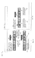
- events for different drives may be processed independently. That is, when the data storage system software receives an event notification for one drive (e.g., event notification regarding occurrence of the drive coming online, or notification regarding some drive activity occurring for the one drive such as sparing), processing for the event may be performed (e.g. sparing) with respect to only the single one drive, such as using the single drive's information (e.g., serial number, capacity, location, etc.) and such processing may not check events or information of any other drives. Users may have confusing experiences and results due to possible inconsistent different behaviors for the same drive operation, and even possibly data loss. To further illustrate such problems that may arise in an embodiment not in accordance with techniques herein, consider the table 100 of FIG. 4 with various examples of different results that may be obtained responsive to performing the same or similar operations.
- an event notification for one drive e.g., event notification regarding occurrence of the drive coming online, or notification regarding some drive activity occurring for the one drive such as sparing
- processing for the event may be performed (e.g. sparing) with respect to
- the table 100 includes 4 example cases or scenarios that may occur. Each of the four cases is represented by information in a single row of table 100 .
- Table 100 includes a first column 102 identifying the user operations performed for the particular case, a second column 104 identifying a first result or behavior responsive to the user operations indicated in column 102 of the same row, and a third column 106 identifying a second different result or behavior responsive to the user operations indicated in column 102 .
- the user operation 110 a may be to pull a consumed user drive and insert the consumed user drive into a system slot.
- Element 110 b indicates that the user experiences a first result if the insertion of the consumed user drive into the system drive slot occurs within an amount of time that is less than a predetermined amount of time
- element 110 c indicates that the user experiences a second different results if the insertion occurs after the foregoing predetermined amount of time has elapsed.
- the predetermined amount of time may be, for example 5 minutes. After the predetermined amount of time has elapsed, the system automatically replaces the pulled consumed user drive of the RAID group with a new spare drive such as described in connection with FIG. 3A .
- the system when the user drive (such as belonging to a configured RAID group) is pulled and inserted into a system drive slot within the predetermined amount of time, the system has not yet replaced the pulled user drive with a spare drive.
- the system software receives a drive online notification due to the insertion of the user drive into the system slot and the predetermined amount of time has not elapsed, the system may determine that the inserted drive's identity is a consumed user drive and may therefore not export the inserted drive for use as a system drive.
- the predetermined amount of time elapses and the system may automatically replace the pulled user drive of the RAID group with a new spare drive.
- the consumed user drive inserted into the system drive slot is not checked when processing eventually replaces the consumed user drive of the RAID group with the spare drive.
- the pulled user drive which has been inserted into the system drive slot remains non-exported and is not used as a system drive even though the pulled user drive is no longer considered “consumed” and a member of the RAID group since the pulled user drive has now been replaced with the spare drive (which is now recognized as consumed and a member of the RAID group).
- the data storage system may implement features as described in FIG. 3B and therefore determine the inserted drive as a new drive.
- the inserted drive is no longer recognized as a consumed user drive because it has lost is membership within the user RAID group as a result of previously being replaced by the spare drive.
- the inserted drive (formerly a consumed user drive) is now recognized as a new drive and is exported for use as a system drive.
- the user operation 112 a may be to pull a system drive, insert the system drive into a user drive slot and insert a new drive into the system slot.
- Element 112 b denotes a first sequential ordering of the foregoing steps as follows:
- Step A 1 Pull a system drive
- Step B 1 Insert new drive into the system slot.
- Step C 1 Insert the pulled system drive into a user drive slot.
- Element 112 c denotes a second different sequential ordering of the foregoing steps as follows:
- Step A 1 Pull a system drive
- Step C 1 Insert the pulled system drive into a user drive slot.
- Step B 1 Insert new drive into the system slot.
- a system may protect a system drive from being erased when it is inserted into a user drive slot. Additionally, when a new drive or an unconsumed user drive (i.e., the drive which is not consumed or is not a member of any user RAID group) is inserted into the system drive slot, it will be consumed as a new system drive, replacing the original one.
- a new drive or an unconsumed user drive i.e., the drive which is not consumed or is not a member of any user RAID group
- step B 1 when the user first inserts the new drive into system slot (step B 1 ), the new drive is consumed as a new system drive which is exported to the user.
- the new drive that is inserted is now recognized or identified as the system drive and the pulled system drive loses its identity as the system drive (e.g., the pulled system drive has been replaced by the new drive now recognized as the system drive).
- step C 1 the user then performs step C 1 and inserts the pulled system drive (no longer recognized as a system drive) into the user drive slot.
- step C 1 in 112 b the system drive inserted into the user drive slot is now recognized as a new drive (since the data storage system has replaced the pulled system drive with a new system drive in step B 1 and therefore no longer recognizes the drive inserted into the user drive slot in step C 1 as a system drive.
- step C 1 the ordering of steps B 1 and C 1 are now reversed so a user first inserts the system drive into the user slot (step C 1 ) prior to inserting a new drive into the system drive slot (step B 1 ).
- step C 1 the system drive is inserted into the user drive slot
- the data storage system determines that the inserted drive is a system drive and is therefore not exported to the user for use as a user drive.
- step B is now performed where the user inserts the new drive into the system slot, the new drive is consumed and used as a new system drive.
- step C 1 Since event processing for each of the foregoing drives is performed independently, which means the original system drive in the user slot is not checked when the new drive is consumed as a new system drive, the original system drive inserted into a user drive slot in step C 1 remains non-exported though it is not recognized as system drive anymore after completing step B 1 . This may seem unreasonable to the user.
- the user operation 114 a may be to swap a system drive and an unconsumed or unconfigured user drive.
- an unconsumed user drive may be a drive that has been inserted into a user drive slot but has not yet been configured or provisioned into a user RAID group.
- an unconsumed user drive may be distinguished from a new drive in that a new drive may not be recognized as having previously been located in a particular user drive slot or a system slot.
- the system drive is located in a system drive slot and the unconsumed user drive is located in a user drive slot and the physical slot locations of the foregoing two drives may be swapped.
- Element 114 b denotes a first sequential ordering of the foregoing steps as follows:
- Step A 2 Pull a system drive from a system drive slot and pull the unconsumed user drive from the user drive slot.
- Step B 2 Insert unconsumed user drive into the system slot (of the pulled system drive).
- Step C 2 Insert the pulled system drive into a user drive slot (of the unconsumed user drive).
- Element 114 c denotes a second different sequential ordering of the foregoing steps as follows:
- Step A 2 Pull a system drive from a system drive slot and pull the unconsumed user drive from the user drive slot.
- Step C 2 Insert the pulled system drive into a user drive slot (of the unconsumed user drive).
- Step B 2 Insert unconsumed user drive into the system slot (of the pulled system drive).
- a system may protect a system drive from being erased when it is inserted into a user drive slot. Additionally, when a new drive or an unconsumed user drive (i.e., the drive which is not consumed or is not a member of any user RAID group) is inserted into the system drive slot, it will be consumed as a new system drive, replacing the original one.
- a new drive or an unconsumed user drive i.e., the drive which is not consumed or is not a member of any user RAID group
- step B 2 when the user first inserts the unconsumed user drive into system slot (step B 2 ), the unconsumed user drive is consumed as a new system drive which is exported to the user.
- the unconsumed user drive that is inserted is now recognized or identified as the system drive and the pulled system drive loses its identity as the system drive (e.g., the pulled system drive has been replaced by the new drive now recognized as the system drive).
- step C 2 the user then performs step C 2 and inserts the pulled system drive (no longer recognized as a system drive) into the user drive slot.
- step C 2 in 114 b the system drive inserted into the user drive slot is now recognized as a new drive (since the data storage system has replaced the pulled system drive with a new system drive in step B 2 and therefore no longer recognizes the drive inserted into the user drive slot in step C 2 as a system drive.
- step C 2 the data storage system determines that the inserted drive is a system drive and is therefore not exported to the user for use as a user drive.
- step B 2 the unconsumed user drive is consumed and used as a new system drive.
- step C 2 Since event processing for each of the foregoing drives is performed independently, which means the original system drive in the user slot is not checked when the unconsumed user drive is consumed as a new system drive, the original system drive inserted into a user drive slot in step C 2 remains non-exported though it is not recognized as system drive anymore after completing step B 2 . This may seem unreasonable to the user.
- the user operation 116 a may be to swap a system drive and a consumed user drive.
- the system drive is located in a system drive slot and the consumed user drive is located in a user drive slot and the physical slot locations of the foregoing two drives may be swapped.
- a data storage system may perform processing to automatically replace a pulled consumed user drive of a RAID group with a spare drive after a predetermined amount of time, such as 5 minutes, has elapsed.
- Element 116 b denotes results from the following ordering of steps:
- Step A 3 Pull a system drive from a system drive slot and pull the consumed user drive from the user drive slot.
- Step B 3 Insert the pulled system drive into a user drive slot (of the consumed user drive).
- Step C 3 Prior to the predetermined time period elapsing, insert consumed user drive into the system slot (of the pulled system drive).
- a system may protect a system drive from being erased when it is inserted into a user drive slot. Additionally, when a new drive or an unconsumed user drive (i.e., the drive which is not consumed or is not a member of any user RAID group) is inserted into the system drive slot, it will be consumed as a new system drive, replacing the original one.
- a new drive or an unconsumed user drive i.e., the drive which is not consumed or is not a member of any user RAID group
- the inserted system drive is not exported for use as a user drive since it is recognized as a system drive from its prior system drive slot location.
- the consumed user drive inserted into the system drive slot is recognized as a consumed user drive of the configured RAID group and is not exported and is not used as a system drive.
- neither the system drive nor the consumed user drive are exported for use in their newly inserted slots.
- Element 116 c denotes two different results that may occur for different sequential ordering of steps where one of the steps includes inserting the consumed user drive into the system slot (of the pulled system drive) AFTER the predetermined time period has elapsed whereby, as described above, after the time period elapses, the data storage system automatically replaces the pulled consumed user drive with a spare drive.
- Element 116 c denotes a first variation that results from the following ordering of steps:
- Step A 4 Pull a system drive from a system drive slot and pull the consumed user drive from the user drive slot.
- Step B 4 Insert the pulled system drive into a user drive slot (of the consumed user drive).
- Step C 4 AFTER the predetermined time period has elapsed, insert consumed user drive into the system slot (of the pulled system drive).
- Element 116 d also denotes a second different sequential ordering of the foregoing steps as follows:
- Step A 4 Pull a system drive from a system drive slot and pull the consumed user drive from the user drive slot.
- Step C 4 AFTER the predetermined time period has elapsed, insert consumed user drive into the system slot (of the pulled system drive).
- Step B 4 Insert the pulled system drive into a user drive slot (of the consumed user drive).
- the first and second variations have different orderings for performing steps B 4 and C 4 as compared to 116 d.
- a system may protect a system drive from being erased when it is inserted into a user drive slot. Additionally, when a new drive or an unconsumed user drive (i.e., the drive which is not consumed or is not a member of any user RAID group) is inserted into the system drive slot, it will be consumed as a new system drive, replacing the original one.
- a new drive or an unconsumed user drive i.e., the drive which is not consumed or is not a member of any user RAID group
- a user first inserts the system drive into the user slot (step B 4 ) prior to inserting the consumed user drive into the system drive slot after the predetermined time period has elapsed (step C 4 ).
- step B 4 the system drive is inserted into the user drive slot
- the data storage system determines that the inserted drive is a system drive and is therefore not exported to the user for use as a user drive.
- step C 4 is now performed where the user inserts the consumed user drive into the system slot after the time period has elapsed.
- the system has already replaced the consumed user drive with a spare drive and thus the consumed user drive now being inserted is no longer recognized by the system has being a consumed user drive. Rather, the consumed user drive now being inserted is recognized as a new drive (e.g., neither recognized as a user drive nor a system drive) and exported to the user for use as a new system drive.
- a new drive e.g., neither recognized as a user drive nor a system drive
- step C 4 when the user first inserts the consumed user drive into system slot after the predetermined time has elapsed (step C 4 ), the system has already replaced the consumed user drive with a spare drive. Thus, the system no longer recognizes the inserted drive as a consumed user drive but rather as a new drive that is exported to for use as a new system drive. Similarly, as a result of performing C 4 , the pulled system drive also loses its identity as a system drive due to the new system drive recognition just described. After performing step C 4 , step B 4 is performed in which the pulled system drive is inserted into the user drive slot.
- the previously pulled system drive now being inserted is no longer recognized as a system drive and is therefore recognized and exported as a new consumed user drive that is a member of the RAID group.
- the new user drive may be initialized with data of the RAID group so that new user drive may be used to service I/Os directed to the RAID group.
- an embodiment in accordance with techniques herein may use deferred drive processing to associate processing of events across different drives.
- deferred drive processing when the data storage system software receives a drive online event notification, it is determined whether the current event can be processed at the current time. The data storage system software may not be able to determine any action to take in response to the event occurrence yet. For example, determination of how to process the current event and drive coming online requires additional information such as related to another subsequent event that has not yet occurred.
- the data storage system may be able to process the current event of the drive coming online at the current time and, additionally, there may be multiple possible actions that can be taken whereby selection of which action to perform (e.g. action regarding how to process or handle the event) is dependent on, or may vary with, a future subsequent event that has not yet occurred.
- selection of which action to perform e.g. action regarding how to process or handle the event
- a selection of which of the multiple actions to take is deferred until such time that the future subsequent event occurs thereby enabling selection of one of the multiple actions. Deferred drive processing is described in more detail in following paragraphs
- a first type of queue may be referred to as the drive processing queue including entries each representing an event occurrence for a drive which needs to be processed.
- the event notification may include information regarding the event, such as, for example, information about the drive causing the event.
- An entry in the drive processing queue may also be referred to as a drive element whereby the drive element is a data structure including information about the drive for which the online event notification has been generated.
- the drive element may include information about the drive such as, for example, the drive's serial number, location or physical position (e.g., slot position), drive storage capacity, drive type (e.g., flash or solid state drive, SAS, NL-SAS, SATA, FC (Fibre channel)) and the like.
- the drive element may, more generally, also include information which generated by the data storage system for usage internally by the data storage system and its processing software.
- a second type of queue may be referred to as a deferred drive queue which includes entries each representing an event occurrence for a drive which needs to be processed and, additionally, where such processing has been deferred.
- a deferred drive queue which includes entries each representing an event occurrence for a drive which needs to be processed and, additionally, where such processing has been deferred.
- such code may not able to determine how to process the drive event or may be unable to perform any action at the current time with the event occurrence until additional information associated with a subsequent event is obtained.
- the code may be able to perform an action, such as may be able to select one of multiple possible actions to perform. In this case, a determination may be made to perform a default action in response to the event occurrence for the drive.
- the subsequent event may be an associated or related event with respect to the drive online event notification for the drive.
- the subsequent event may be, for example, another associated drive coming online or associated drive activity of another drive occurring.
- a current event such as the drive online notification, which may be so characterized may be placed in the deferred drive queue to wait for the occurrence of the subsequent related event before processing the current event.
- the deferred drive queue associated with event type I may be searched to locate the drive for processing whose processing had previously been deferred.
- the above-mentioned second queue may be searched to find the deferred drive which needs to be processed.
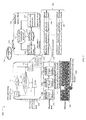
- FIG. 5 shown is an example of a flow diagram with processing logic and associated data structures that may be used in an embodiment in accordance with techniques herein.
- the example 300 illustrates deferred drive processing logic described in more detail below that may be performed in a data storage system in an embodiment.
- the example 300 includes disk enclosure 340 , drive processing queue 330 , drive processing thread 310 , deferred drive discovery thread, and deferred drive queues 346 a - n (denoted in the aggregate by 346 ).
- Drive processing queue 330 is the first type of queue as described above which includes a drive element for each drive for which a drive online event notification has occurred.
- the drive processing queue 330 includes drive elements 330 a - 330 c .
- drive element 330 a includes information identifying the particular drive for which a drive online event notification has occurred.
- Drive element 330 a identifies a first drive located at position 1, 1, 2, having serial number 4E3FA98, identifies the first drive as a SAS drive, and the like.
- drive elements 330 b - c may include identifying information regarding represented drives for which drive online event notifications have occurred and which are awaiting processing by drive processing thread 310 .
- the information in the drive element for a drive may also identify whether the drive was inserted into a system slot location or a user drive slot location in addition to identifying the particular system slot or user slot.
- Element 346 represents queues of the second type mentioned above.
- Element 346 includes the multiple deferred drive queues 346 a - n each representing a different type of drive event.
- Each deferred drive queue 346 a - n may include drive elements representing drives for which processing has been deferred until the occurrence of another event.
- a first drive element representing a first drive which is on a first deferred drive queue associated with event type I indicates that the first drive's processing (e.g., the processing of the previous drive online event notification) has been deferred until the subsequent occurrence of another dependent or related event of type I.
- a drive may be inserted into the disk enclosure 340 of the data storage system, or a drive may recover from a failure.
- a drive online notification with the drive's information may be sent to software executing in the data storage system.
- the executing code may allocate a drive element and place the drive element in the drive processing queue 330 .
- the drive processing thread 330 is awakened.
- the drive processing thread removes 311 one drive element from the drive processing queue and begins to process the drive identified by the drive element.
- the drive element may be placed into the deferred drive queue corresponding to event i if either of the following is true:
- the drive processing thread cannot determine how to process the drive represented by the current drive element until event i occurs.
- the thread is able to process the drive represented by the drive element but the processing performed has to be changed when and if event i subsequently occurs.
- a drive element is selected from the drive processing queue 330 .
- a determination is made as to whether the drive represented by the selected drive element can be processed at the current time.
- the particular criteria used to determine whether to process the event and associated drive represented by the drive element at the current time, or whether to defer such processing, may vary with system and embodiment. For example, the criteria may include determining whether any additional information regarding future event occurrences or activities is needed in order to process the current drive online event represented by the drive element being processing. If so, then step 312 would evaluate to no.
- step 312 evaluates to no, control proceeds to step 314 where the drive element is placed in the appropriate deferred drive queue for event I, whereby the drive represented by the drive element can be processed once a subsequent event of type I occurs. If step 312 evaluates to yes, and one or more actions or alternative processing may be performed for the drive, control proceeds to 316 .
- step 316 a determination is made as to whether there is sufficient information at the current time to select one particular action, from the one or more possible actions, to be performed. Step 316 may evaluate to no, for example, if additional information is needed in order to select an action and processing to be performed. The additional information may be for example, information in connection with one or more subsequent events that have not yet occurred.
- step 316 evaluates to no, control proceeds to 314 where the current drive element is placed on the deferred drive queue for event I (as described above).
- the particular deferred drive queue upon which a drive element is placed in step 314 may depend upon the drive element itself and the particular event occurrence represented by the drive element and may also depend upon the state of the system, such as the state of other drives, drive slots, and the like. If step 316 evaluates to yes, control proceeds to step 317 to process the current drive and associated drive element. From step 316 , control proceeds to step 310 to process a next drive element, if any, in the drive processing queue 330 .
- an event occurs.
- drive related event i 350 e.g. drive sparing
- This thread 320 searches the deferred drive queue 346 a corresponding to event i 350 to determine the drive(s) denoted by drive elements in queue 346 a which can be processed now that this specific event 350 has occurred.
- the matched one or more drive elements are then placed 336 into the drive processing queue 330 and the drive processing thread 310 is awakened.
- drive processing thread may then processes the drive element(s) just moved to the drive processing queue 330 based on the current system state after event i occurs.
- processing performed by the deferred drive discovery thread 320 may also include updating the one or more matched drive elements moved from one of the deferred drive queues 346 to the drive processing queue 330 .
- Such updating may include updating information of the matched drive element to include additional or modified information in accordance with the particular event that has occurred as matched to the drive element.
- processing performed by the deferred drive discovery thread 320 may be described further as follows where the thread is searching a deferred drive queue for event type I and there has been an occurrence of an event of type I.
- the thread may select a next drive element from the deferred drive queue of event type I.
- a determination is made as to whether the current drive element may now be processed as a result of the occurrence of the event of type I. If step 322 evaluates to yes and it can now be processed, control proceeds to step 323 where the current drive element is placed in the drive processing queue.
- step 321 If step 322 evaluates to no and the current drive element cannot be processed yet, control proceeds to step 324 where the drive element remains on the deferred drive queue for event type I and then control proceeds to step 321 to process any remaining drive elements.
- thread 320 may stop processing drive elements when all elements in the particular deferred drive queue for event type I have been examined.
- step 322 may be characterized as determining a match or correspondence between the event occurrence of type I and one or more drive elements included in the deferred drive queue for event type I. Such a match or correspondence may represent that the event occurrence of type I relates to a previous event corresponding to the matching drive element (e.g., previous drive online event). A match may be determined between event information (for the occurrence of event I) and drive element information of the drive elements included in the deferred drive queue for event type I.
- An embodiment utilizing the deferred drive processing as just described in connection with drive-related events may provide the users with a more consistent result and experience when performing drive operations. Furthermore, use of such techniques in an embodiment which also performs processing and supports features such as described in FIGS. 3A-B provides for eliminating the risk of data loss and data unavailability that may otherwise result as described, for example, in connection with cases of FIG. 4 . To further illustrate, discussion now reconsiders the exemplary cases and user experience previously described in connection with FIG. 4 with the difference now of performing deferred drive processing in a data storage system.
- a table 400 various examples of cases and results that may be obtained in an embodiment in accordance with techniques herein using deferred drive processing.
- the table 400 includes 4 example cases or scenarios that may occur.
- the cases in table 400 correspond to those previously described above in connection with FIG. 4 .
- Each of the four cases is represented by information in a single row of table 400 .
- Table 400 includes a first column 402 identifying the user operations performed for the particular case, and a second column 104 identifying a result or behavior experience in response to the user operations indicated in column 102 of the same row.
- the user operation 406 a may be to pull a consumed user drive and insert the consumed user drive into a system slot.
- a user experienced different resulting behavior that may vary with the amount of time between when the consumed user drive is pulled and when it is inserted into the system slot.
- the system automatically selects a spare to become a new user drive of the configured RAID group thereby replacing the pulled user drive.
- the consumed user drive has not yet been replaced by a spare drive in the user RAID group.
- the drive online event notification is received and a drive element is allocated and placed in the drive processing queue 330 .
- the drive processing thread 310 processes the drive element and determines that the drive's identity is a consumed user drive which has been placed in a system drive slot. This may be determined, for example, based on the location information of the drive element which may denote a system slot location.
- the drive element includes information, such as a serial number which corresponds to identifying information of a consumed user drive of a configured user RAID group.
- the data storage system previously stored information, such as drive serial number, type, etc., used to uniquely identify each of the particular user drives. Now, the system may determine that one such consumed user drive is identified by the drive element being processed whereby the consumed user drive is located in the system slot. At this point, the inserted drive's identity is determined as a consumed user drive that has been inserted into a system slot so the inserted drive is not exported for use as a system drive.
- the executing code determines that after the predetermined amount of time has elapsed, the consumed user drive will be replaced later by a spare drive thereby allowing the consumed user drive to be used as a system drive after such subsequent sparing event occurs.
- the thread 310 places the drive element for this user drive into the deferred drive queue corresponding to a spare event.
- the deferred drive discovery thread 320 When the predetermined time period after which sparing occurs has elapsed, the consumed user drive is replaced by a spare drive thereby causing generation of a sparing event.
- the deferred drive discovery thread 320 In response to the sparing event, the deferred drive discovery thread 320 is awakened which then searches the deferred drive queue of 346 corresponding to the type of event that has occurred, the sparing event type. The deferred drive discovery thread 320 determines that the drive element corresponding to the consumed user drive can now be processed since the related sparing event (whereby the spare replaced the consumed user drive as a drive member of the configured user RAID group) has occurred. Processing is performed to determine one or more drive elements of the sparing event queue which match the sparing event information.
- the sparing event information may, for example, identify (e.g., by serial number or other information) the consumed user drive that was replaced by the spare.
- the drive element in the deferred drive queue for sparing event determined as a match may identify the same drive via matching serial numbers (e.g., serial number of sparing event information matches serial number of drive associated with the drive element).
- thread 320 places the drive element for the consumed user drive on the drive processing queue 330 since the event and drive represented by the drive element (e.g., the consumed user drive previously inserted into the system slot) can now be processed given that the subsequent related sparing event has occurred.
- the drive element moved from one of the deferred drive queues 346 to the drive processing queue 330 may be updated, as needed, to include additional event about the related sparing event that has also now occurred.
- the drive processing thread 310 again processes the inserted drive element. However, at this point, the drive processing thread 310 determines that the drive represented by the drive element no longer has an identity in the system as a consumed user drive because no user configured RAID group is identified as having this particular inserted drive as a RAID group member. Rather, the drive may be viewed as a new drive that is exported as a new system drive as represented by 406 b.
- the drive represented by the created drive element can be processed immediately and there is no need to place the drive element on a deferred drive processing queue.
- the inserted drive is no longer recognized as a consumed user drive since the spare drive is now recognized as the RAID group member rather than the inserted drive.
- processing proceeds as outlined above and the inserted drive (previously recognized as a consumed user drive but now recognized as a new drive) inserted into the system slot is now exported as a new system drive as represented by 406 b .
- the behavior or result is the same in both variations (e.g., whether the pulled consumed user drive is inserted into the system slot before or after the predetermined amount of time elapsed between being pulled and inserted).
- the user operation 408 a may be to pull a system drive, insert the system drive into a user drive slot and insert a new drive into the system slot.
- a first behavior or result was obtained if the user first inserted the system drive into the user slot, and then secondly inserted the new drive into the system slot.
- a second different behavior or result was obtained if the foregoing ordering was changed so that the user first inserted the new drive into the system slot and then secondly inserted the system drive into the user drive slot.
- the same result or behavior is obtained regardless of the foregoing ordering. In other words, the same behavior results for both sequences.
- a user pulls a system drive from its system drive slot location.
- a drive element is created for the system drive and placed in the drive processing queue 330 .
- the foregoing drive element is then processed by the drive processing thread 310 which recognizes the inserted drive (inserted into the user drive slot) as a system drive, so it is not exported to user.
- the system recognizes the inserted drive as a system drive since, previously, the inserted drive was located in the system drive slot and used as a system drive.
- Information identifying the inserted drive such as serial number, etc., was stored and associated with its position and use as a system drive.
- the inserted drive is detected as having identifying information matching that of a system drive.
- the drive processing thread 310 also knows that at a later point in time, an event may occur in which a new drive is inserted into the system drive slot previously occupied by the system drive.
- the inserted system drive (inserted now in the user drive slot) may be exported and used as a user drive. So, the drive processing thread places the drive element for the inserted system drive into the deferred drive queue corresponding to the new system drive event type.
- the user inserts the new drive into the system slot where the new drive is consumed and exported as a new system drive (as represented in 408 b ).
- This new system drive event triggers the deferred drive discovery thread to search the deferred drive queue corresponding to new system drive event whereby such searching looks for a drive element matching or corresponding to (e.g., related to) the new system drive event.
- a match between the new system drive event occurrence and a drive element in the new system drive event queue may be made by determining a match or correspondence between information of the new system drive event occurrence and information of the drive element.
- the new system drive may be inserted into a particular system slot location previously occupied by the pulled system drive.
- the new system drive event information may identify the system drive that was replaced (e.g., by serial number of the replaced drive).
- the matching drive element of the pulled system drive in the deferred drive queue may have the same identifier (denoting the pulled system drive).
- Processing locates the drive element on the new system drive event queue where the drive element identifies the previous system drive now inserted into the user drive slot, and then places the drive element into the drive processing queue.
- the drive element moved to the drive processing queue 330 may be updated, as needed, to include additional event about the related new system drive event that has also now occurred.
- the drive processing thread processes this drive element again, it determines the drive's identity is a new drive (because its identity as a system drive has been replaced by the new drive inserted in the system drive slot).
- the drive previously recognized as a system drive and now recognized as a new drive that is inserted into the user drive slot
- the drive is exported to the user to use as a new user drive as in 408 b.
- the drive element corresponding to the event of the new drive being inserted may be processed immediately without placing the drive element in a deferred drive processing queue.
- the user then inserts the pulled system drive into a user drive slot and the created drive element for this event may also be processed immediately without use of deferred drive queues.
- the inserted drive is no longer recognized as one of the system drives since the new system drive replaced the pulled system drive after inserting the new drive in the pulled system drive's original system slot.
- the previously pulled system drive is now recognized as a new user drive and exported as such to the user, as indicated in 408 b.
- the user operation 410 a may be to swap a system drive, currently located in a system drive slot, and an unconsumed or unconfigured user drive, currently located in a user drive slot. Described above in connection with row 114 of FIG. 4 , two variations were described with different results depending on the particular ordering of the steps. A first behavior or result was obtained if the user first inserted the system drive into the user slot (previously occupied by the unconsumed user drive), and then secondly inserted the unconfigured or unconsumed drive into the system slot (previously occupied by the pulled system drive).
- a second different behavior or result was obtained if the foregoing ordering was changed so that the user first inserted the unconsumed drive into the system slot and then secondly inserted the system drive into the user drive slot (previously occupied by the unconsumed user drive).
- the same result or behavior is obtained regardless of the foregoing ordering. In other words, the same behavior results for both sequences.
- the unconsumed user drive is first inserted into the system drive slot and then the system drive is inserted into the user drive slot.
- processing as in FIG. 5 may be performed whereby a drive element is created and placed in the drive processing queue for the unconsumed user drive.
- the drive processing thread determines that this drive element corresponds to a drive that is not a system drive and is also not recognized as a consumed user drive of any configured user RAID group.
- the unconsumed drive can be immediately processed and (as indicated by 410 b ) is exported as a new system drive replacing the pulled system drive (that previously occupied the system slot into which the unconsumed user drive is inserted).
- the pulled system drive is inserted into the user drive slot and can be processed immediately without placement on a deferred drive queue.
- the inserted drive is no longer recognized as a system drive since its role as a system drive has been replaced by the foregoing unconsumed user drive (now recognized as a new system drive).
- the previously pulled system drive, now inserted into the user drive slot is recognized as a new drive and is exported as a new (unconsumed) user drive, as indicated by 410 b.
- the user inserts the new drive into the system slot (previously occupied by the pulled system drive) where the new drive is consumed and exported as a new system drive (as represented in 408 b ).
- This new system drive event triggers the deferred drive discovery thread to search the deferred drive queue corresponding to new system drive event. Processing is performed to determine any drive element(s) matching the new system drive event that has occurred. Such processing may be determine a match between new system drive event information and drive element information of drive elements in the deferred drive queue for new system drive events.
- the new system drive event information may identify the system drive that was placed (e.g. the serial number and/or other identifying information of the replaced system drive).
- Processing may compare the foregoing new drive event information, such as replaced system drive's serial number, with a serial number and/or other drive identifying information included in with drive elements in the deferred drive queue for new system drive events.
- a matching drive element has matching or corresponding identifying information with that of the replaced system drive.
- Processing locates the drive element on the new system drive event queue where the drive element identifies the previous system drive (now inserted into the user drive slot), and then places the drive element into the drive processing queue.
- the drive element moved from one of the deferred drive queues 346 to the drive processing queue 330 may be updated, as needed, to include additional event about the related new system drive event that has also now occurred.
- the drive processing thread processes this drive element again, it determines the drive's identity is a new drive (because its identity as a system drive has been replaced by the new drive inserted in the system drive slot). As a result, the drive (previously recognized as a system drive and now recognized as a new drive that is inserted into the user drive slot) is exported to the user to use as a new user drive as in 410 b.
- the system behavior for the third case or scenario 410 is the same regardless of the ordering of the following steps: insert unconsumed user drive into system slot; insert pulled system drive into user drive slot.
- the user operation 412 a may be to swap a system drive and a consumed user drive.
- the system drive is located in a system drive slot and the consumed user drive is located in a user drive slot and the physical slot locations of the foregoing two drives may be swapped.
- a data storage system may perform processing to automatically replace a pulled consumed user drive of a RAID group with a spare drive after a predetermined amount of time, such as 5 minutes, has elapsed.
- deferred drive processing as denoted by 412 b , both drives (system and consumed user drive) are exported to the user for use in their new physical drive slots.
- the same behavior or results 412 b may be obtained for both the following first ordering: insert the pulled system drive into the swapped user drive's location and then insert the pulled consumed user drive into the system drive's slot, and second ordering: insert pulled consumed user drive into the system drive's slot and then insert pulled system drive into swapped user drive's location. Additionally, the same result may be obtained as denoted in 412 b regardless of whether the amount of time that has elapsed from drive pull to insertion exceeds the predetermined amount of time (after which drive sparing automatically occurs for a pulled consumed user drive).
- the consumed user drive is inserted into the system drive slot. If the predetermined amount of time has elapsed since the consumed user drive was pulled from its user drive slot, sparing has already replaced the consumed user drive so that the inserted consumed user drive (inserted into the system slot) is now recognized as a new drive and is exported and used as a new system drive (as in 412 b ) and also triggering a new system drive event occurrence. Consistent with FIG. 5 processing, the deferred drive discovery thread 320 is awakened and searches the new system drive event queue for a drive matching the event occurrence. Processing locates a matching drive element for the above-mentioned system drive inserted into the user drive slot.
- the match may be determined, for example, by matching the new system drive event information with information included in drive elements of the deferred processing queue (for new system drive events).
- the drive element associated with the pulled system drive is placed into the drive processing queue where the drive element is again processed by the drive processing thread 310 .
- the drive element moved to the drive processing queue 330 may be updated, as needed, to include additional event about the related new system drive event that has also now occurred.
- the drive processing thread 310 determines that the drive element can now be processed and the system drive, inserted into the user drive slot in a first event, is determined to have now been replaced by a new system drive in a second subsequent event.
- the foregoing first and second events have been matched as related events and collectively viewed in the aggregate to make a decision on how to handle and use the pulled system drive (now inserted into a user drive slot).
- the pulled system drive (now inserted into a user drive slot) is recognized as a new drive and exported for use as a new user drive, as in 412 b.
- deferred drive processing places the consumed user drive in the deferred processing queue to wait for the occurrence of a related sparing event whereby the spare replaces the consumed user drive after the predetermined amount of time has elapsed. Once this has occurred, processing may continue as outlined above.
- deferred drive processing with the second ordering for case or scenario four 412 : insert pulled consumed user drive into the system drive's slot and then insert pulled system drive into swapped user drive's location.
- deferred drive processing as in FIG. 5 results in creating a drive element for the pulled consumed user drive which is recognized by the system as a consumed user drive and is not exported at the current time as a system drive.
- the system knows that the consumed user drive may be later used as a new system drive after the predetermined amount of time has elapsed causing automatic sparing to replace the consumed user drive with a spare drive.
- the drive element is placed in the deferred drive processing queue for sparing events.
- the consumed user drive is replaced by a spare drive in the configured RAID group thereby generating a sparing event.
- the deferred drive discovery thread is awakened and processes the sparing event queue to determine a matching drive element corresponding to that of the pulled consumed user drive. The match may be determined by matching information from the sparing event with that of the drive element.
- the sparing event may include information identifying the consumed user drive (e.g., serial number, user drive slot location, etc.) that was replaced by the spare.
- the sparing event information may be compared against information of the drive elements in the sparing event queue to determine any matching drive element(s). In this case, a match is determined and the drive element for the pulled consumed user drive is placed in the drive processing queue for processing again by the drive processing thread.
- the drive element moved to the drive processing queue 330 may be updated, as needed, to include additional event about the related sparing event that has also now occurred.
- the drive element representing the pulled consumed user drive (now inserted in the system drive slot) may be exported and used as a new system drive (as in 412 b ) since the subsequent related sparing event replaced the pulled consumed user drive. It should be note that if the predetermined amount of time had elapsed prior to the consumed user drive being inserted, then the consumed user drive would be recognized and exported as a new system drive (as in 412 b ) since the spare drive has replaced the consumed user drive.
- the pulled system drive is inserted into the user drive slot. Consistent with FIG. 5 processing, a drive element is created and can be processed immediately. At this point, the pulled system drive (now inserted into the user drive slot) has been replaced by the above-mentioned new system drive. The inserted drive is now recognized as a new user drive (as in 412 b ) and there is no need to place the drive element on a deferred event queue.
- the example 500 includes states S 1 , S 2 and S 3 denoted by nodes and transitions between the states denoted by directed arrows. A transition from a first state to a second state is represented by a directed arrow from the first state to the second state.
- S 1 may represent a start state wherein upon the occurrence of a first drive online event, the state for the drive brought online transitions to S 2 .
- State S 2 may represent the deferred drive processing state.
- the drive remains in state S 2 while waiting for additional events and/or information. For example, a drive transitions from S 2 to S 2 responsive to a subsequent event occurring upon which the previous first event (drive online event) and associated drive depends.
- a drive transitions from state S 2 to S 3 where the processing for the drive and associated events that have occurred may be processed.
- a transition from S 2 to S 3 occurs with respect to a drive when no subsequent event occurrence is needed to process the drive and any event(s) for the drive that have occurred.
- An embodiment may implement the techniques herein using code executed by a processor.
- an embodiment may implement the techniques herein using code which is executed by a processor.
- the code may be stored on a computer-readable storage medium having any one of a variety of different forms including volatile and nonvolatile, removable and non-removable media implemented in any method or technology for storage of information such as computer readable instructions, data structures, program modules or other data.
- Computer-readable storage media may include, but is not limited to, RAM, ROM, EEPROM, flash memory or other memory technology, CD-ROM, (DVD) or other optical storage, magnetic cassettes, magnetic tape, magnetic disk storage or other magnetic storage devices, or any other medium which can be used to store the desired information and which can accessed by a processor.
Abstract
Description
Claims (20)
Priority Applications (1)
| Application Number | Priority Date | Filing Date | Title |
|---|---|---|---|
| US14/141,310 US9229797B1 (en) | 2013-12-26 | 2013-12-26 | Deferred drive processing |
Applications Claiming Priority (1)
| Application Number | Priority Date | Filing Date | Title |
|---|---|---|---|
| US14/141,310 US9229797B1 (en) | 2013-12-26 | 2013-12-26 | Deferred drive processing |
Publications (1)
| Publication Number | Publication Date |
|---|---|
| US9229797B1 true US9229797B1 (en) | 2016-01-05 |
Family
ID=54939172
Family Applications (1)
| Application Number | Title | Priority Date | Filing Date |
|---|---|---|---|
| US14/141,310 Active 2034-06-26 US9229797B1 (en) | 2013-12-26 | 2013-12-26 | Deferred drive processing |
Country Status (1)
| Country | Link |
|---|---|
| US (1) | US9229797B1 (en) |
Cited By (2)
| Publication number | Priority date | Publication date | Assignee | Title |
|---|---|---|---|---|
| CN110874565A (en) * | 2018-08-30 | 2020-03-10 | 英飞凌科技股份有限公司 | Apparatus and method for event classification based on barometric sensor data |
| CN110874565B (en) * | 2018-08-30 | 2024-04-26 | 英飞凌科技股份有限公司 | Apparatus and method for event classification based on barometric sensor data |
Citations (5)
| Publication number | Priority date | Publication date | Assignee | Title |
|---|---|---|---|---|
| US20020178396A1 (en) * | 2001-04-23 | 2002-11-28 | Wong Joseph D. | Systems and methods for providing automated diagnostic services for a cluster computer system |
| US20130326266A1 (en) * | 2012-05-31 | 2013-12-05 | International Business Machines Corporation | Maximizing Use of Storage in a Data Replication Environment |
| US8782463B1 (en) * | 2011-10-27 | 2014-07-15 | Seagate Technology Llc | Restoring a failed storage volume after removal of a storage device from an array |
| US8782465B1 (en) * | 2011-12-22 | 2014-07-15 | Emc Corporation | Managing drive problems in data storage systems by tracking overall retry time |
| US8853781B2 (en) * | 2011-12-16 | 2014-10-07 | International Business Machines Corporation | Rare-earth oxide isolated semiconductor fin |
-
2013
- 2013-12-26 US US14/141,310 patent/US9229797B1/en active Active
Patent Citations (5)
| Publication number | Priority date | Publication date | Assignee | Title |
|---|---|---|---|---|
| US20020178396A1 (en) * | 2001-04-23 | 2002-11-28 | Wong Joseph D. | Systems and methods for providing automated diagnostic services for a cluster computer system |
| US8782463B1 (en) * | 2011-10-27 | 2014-07-15 | Seagate Technology Llc | Restoring a failed storage volume after removal of a storage device from an array |
| US8853781B2 (en) * | 2011-12-16 | 2014-10-07 | International Business Machines Corporation | Rare-earth oxide isolated semiconductor fin |
| US8782465B1 (en) * | 2011-12-22 | 2014-07-15 | Emc Corporation | Managing drive problems in data storage systems by tracking overall retry time |
| US20130326266A1 (en) * | 2012-05-31 | 2013-12-05 | International Business Machines Corporation | Maximizing Use of Storage in a Data Replication Environment |
Cited By (2)
| Publication number | Priority date | Publication date | Assignee | Title |
|---|---|---|---|---|
| CN110874565A (en) * | 2018-08-30 | 2020-03-10 | 英飞凌科技股份有限公司 | Apparatus and method for event classification based on barometric sensor data |
| CN110874565B (en) * | 2018-08-30 | 2024-04-26 | 英飞凌科技股份有限公司 | Apparatus and method for event classification based on barometric sensor data |
Similar Documents
| Publication | Publication Date | Title |
|---|---|---|
| US20220019361A1 (en) | Data-protection-aware capacity provisioning of shared external volume | |
| US8843917B1 (en) | Techniques for parallel drive upgrade while maintaining host accessibility | |
| US20180260123A1 (en) | SEPARATION OF DATA STORAGE MANAGEMENT ON STORAGE devices FROM LOCAL CONNECTIONS OF STORAGE DEVICES | |
| US7434012B1 (en) | Techniques for media scrubbing | |
| US8027263B2 (en) | Method to manage path failure threshold consensus | |
| US9262087B2 (en) | Non-disruptive configuration of a virtualization controller in a data storage system | |
| WO2016110004A1 (en) | Management method and apparatus for disk storage space, and storage device | |
| US11461085B2 (en) | Firmware upgrade method in multiple node storage system | |
| US8010490B2 (en) | Apparatus for managing remote copying between storage systems | |
| US8849966B2 (en) | Server image capacity optimization | |
| WO2018173164A1 (en) | Data processing system | |
| US9792056B1 (en) | Managing system drive integrity in data storage systems | |
| US20090083474A1 (en) | File allocation table management | |
| JP2012507788A (en) | Method and system for recovering a computer system using a storage area network | |
| US9684475B2 (en) | Multi-mode hybrid storage drive | |
| US10263844B1 (en) | Techniques for performing an upgrade | |
| US20160139834A1 (en) | Automatic Configuration of Local Storage Resources | |
| US7983171B2 (en) | Method to manage path failure thresholds | |
| US9940073B1 (en) | Method and apparatus for automated selection of a storage group for storage tiering | |
| US8904122B2 (en) | Self-adjusting SCSI storage port queue | |
| US10296218B2 (en) | Update control method, update control apparatus, and storage medium | |
| US8996769B2 (en) | Storage master node | |
| US10657005B2 (en) | Comingling conventional and backup volumes in tiered storage systems | |
| US9781057B1 (en) | Deadlock avoidance techniques | |
| US9626117B2 (en) | Computer system and management method for computer system |
Legal Events
| Date | Code | Title | Description |
|---|---|---|---|
| AS | Assignment |
Owner name: EMC CORPORATION, MASSACHUSETTS Free format text: ASSIGNMENT OF ASSIGNORS INTEREST;ASSIGNORS:HU, ZHIPENG;GAO, JIAN;HEI, WEI;AND OTHERS;REEL/FRAME:032185/0374 Effective date: 20140108 |
|
| AS | Assignment |
Owner name: EMC CORPORATION, MASSACHUSETTS Free format text: ASSIGNMENT OF ASSIGNORS INTEREST;ASSIGNOR:CASSANO, MARC;REEL/FRAME:032193/0761 Effective date: 20140211 |
|
| STCF | Information on status: patent grant |
Free format text: PATENTED CASE |
|
| AS | Assignment |
Owner name: CREDIT SUISSE AG, CAYMAN ISLANDS BRANCH, AS COLLATERAL AGENT, NORTH CAROLINA Free format text: SECURITY AGREEMENT;ASSIGNORS:ASAP SOFTWARE EXPRESS, INC.;AVENTAIL LLC;CREDANT TECHNOLOGIES, INC.;AND OTHERS;REEL/FRAME:040134/0001 Effective date: 20160907 Owner name: THE BANK OF NEW YORK MELLON TRUST COMPANY, N.A., AS NOTES COLLATERAL AGENT, TEXAS Free format text: SECURITY AGREEMENT;ASSIGNORS:ASAP SOFTWARE EXPRESS, INC.;AVENTAIL LLC;CREDANT TECHNOLOGIES, INC.;AND OTHERS;REEL/FRAME:040136/0001 Effective date: 20160907 Owner name: CREDIT SUISSE AG, CAYMAN ISLANDS BRANCH, AS COLLAT Free format text: SECURITY AGREEMENT;ASSIGNORS:ASAP SOFTWARE EXPRESS, INC.;AVENTAIL LLC;CREDANT TECHNOLOGIES, INC.;AND OTHERS;REEL/FRAME:040134/0001 Effective date: 20160907 Owner name: THE BANK OF NEW YORK MELLON TRUST COMPANY, N.A., A Free format text: SECURITY AGREEMENT;ASSIGNORS:ASAP SOFTWARE EXPRESS, INC.;AVENTAIL LLC;CREDANT TECHNOLOGIES, INC.;AND OTHERS;REEL/FRAME:040136/0001 Effective date: 20160907 |
|
| AS | Assignment |
Owner name: EMC IP HOLDING COMPANY LLC, MASSACHUSETTS Free format text: ASSIGNMENT OF ASSIGNORS INTEREST;ASSIGNOR:EMC CORPORATION;REEL/FRAME:040203/0001 Effective date: 20160906 |
|
| AS | Assignment |
Owner name: THE BANK OF NEW YORK MELLON TRUST COMPANY, N.A., T Free format text: SECURITY AGREEMENT;ASSIGNORS:CREDANT TECHNOLOGIES, INC.;DELL INTERNATIONAL L.L.C.;DELL MARKETING L.P.;AND OTHERS;REEL/FRAME:049452/0223 Effective date: 20190320 Owner name: THE BANK OF NEW YORK MELLON TRUST COMPANY, N.A., TEXAS Free format text: SECURITY AGREEMENT;ASSIGNORS:CREDANT TECHNOLOGIES, INC.;DELL INTERNATIONAL L.L.C.;DELL MARKETING L.P.;AND OTHERS;REEL/FRAME:049452/0223 Effective date: 20190320 |
|
| MAFP | Maintenance fee payment |
Free format text: PAYMENT OF MAINTENANCE FEE, 4TH YEAR, LARGE ENTITY (ORIGINAL EVENT CODE: M1551); ENTITY STATUS OF PATENT OWNER: LARGE ENTITY Year of fee payment: 4 |
|
| AS | Assignment |
Owner name: THE BANK OF NEW YORK MELLON TRUST COMPANY, N.A., TEXAS Free format text: SECURITY AGREEMENT;ASSIGNORS:CREDANT TECHNOLOGIES INC.;DELL INTERNATIONAL L.L.C.;DELL MARKETING L.P.;AND OTHERS;REEL/FRAME:053546/0001 Effective date: 20200409 |
|
| AS | Assignment |
Owner name: WYSE TECHNOLOGY L.L.C., CALIFORNIA Free format text: RELEASE BY SECURED PARTY;ASSIGNOR:CREDIT SUISSE AG, CAYMAN ISLANDS BRANCH;REEL/FRAME:058216/0001 Effective date: 20211101 Owner name: SCALEIO LLC, MASSACHUSETTS Free format text: RELEASE BY SECURED PARTY;ASSIGNOR:CREDIT SUISSE AG, CAYMAN ISLANDS BRANCH;REEL/FRAME:058216/0001 Effective date: 20211101 Owner name: MOZY, INC., WASHINGTON Free format text: RELEASE BY SECURED PARTY;ASSIGNOR:CREDIT SUISSE AG, CAYMAN ISLANDS BRANCH;REEL/FRAME:058216/0001 Effective date: 20211101 Owner name: MAGINATICS LLC, CALIFORNIA Free format text: RELEASE BY SECURED PARTY;ASSIGNOR:CREDIT SUISSE AG, CAYMAN ISLANDS BRANCH;REEL/FRAME:058216/0001 Effective date: 20211101 Owner name: FORCE10 NETWORKS, INC., CALIFORNIA Free format text: RELEASE BY SECURED PARTY;ASSIGNOR:CREDIT SUISSE AG, CAYMAN ISLANDS BRANCH;REEL/FRAME:058216/0001 Effective date: 20211101 Owner name: EMC IP HOLDING COMPANY LLC, TEXAS Free format text: RELEASE BY SECURED PARTY;ASSIGNOR:CREDIT SUISSE AG, CAYMAN ISLANDS BRANCH;REEL/FRAME:058216/0001 Effective date: 20211101 Owner name: EMC CORPORATION, MASSACHUSETTS Free format text: RELEASE BY SECURED PARTY;ASSIGNOR:CREDIT SUISSE AG, CAYMAN ISLANDS BRANCH;REEL/FRAME:058216/0001 Effective date: 20211101 Owner name: DELL SYSTEMS CORPORATION, TEXAS Free format text: RELEASE BY SECURED PARTY;ASSIGNOR:CREDIT SUISSE AG, CAYMAN ISLANDS BRANCH;REEL/FRAME:058216/0001 Effective date: 20211101 Owner name: DELL SOFTWARE INC., CALIFORNIA Free format text: RELEASE BY SECURED PARTY;ASSIGNOR:CREDIT SUISSE AG, CAYMAN ISLANDS BRANCH;REEL/FRAME:058216/0001 Effective date: 20211101 Owner name: DELL PRODUCTS L.P., TEXAS Free format text: RELEASE BY SECURED PARTY;ASSIGNOR:CREDIT SUISSE AG, CAYMAN ISLANDS BRANCH;REEL/FRAME:058216/0001 Effective date: 20211101 Owner name: DELL MARKETING L.P., TEXAS Free format text: RELEASE BY SECURED PARTY;ASSIGNOR:CREDIT SUISSE AG, CAYMAN ISLANDS BRANCH;REEL/FRAME:058216/0001 Effective date: 20211101 Owner name: DELL INTERNATIONAL, L.L.C., TEXAS Free format text: RELEASE BY SECURED PARTY;ASSIGNOR:CREDIT SUISSE AG, CAYMAN ISLANDS BRANCH;REEL/FRAME:058216/0001 Effective date: 20211101 Owner name: DELL USA L.P., TEXAS Free format text: RELEASE BY SECURED PARTY;ASSIGNOR:CREDIT SUISSE AG, CAYMAN ISLANDS BRANCH;REEL/FRAME:058216/0001 Effective date: 20211101 Owner name: CREDANT TECHNOLOGIES, INC., TEXAS Free format text: RELEASE BY SECURED PARTY;ASSIGNOR:CREDIT SUISSE AG, CAYMAN ISLANDS BRANCH;REEL/FRAME:058216/0001 Effective date: 20211101 Owner name: AVENTAIL LLC, CALIFORNIA Free format text: RELEASE BY SECURED PARTY;ASSIGNOR:CREDIT SUISSE AG, CAYMAN ISLANDS BRANCH;REEL/FRAME:058216/0001 Effective date: 20211101 Owner name: ASAP SOFTWARE EXPRESS, INC., ILLINOIS Free format text: RELEASE BY SECURED PARTY;ASSIGNOR:CREDIT SUISSE AG, CAYMAN ISLANDS BRANCH;REEL/FRAME:058216/0001 Effective date: 20211101 |
|
| AS | Assignment |
Owner name: SCALEIO LLC, MASSACHUSETTS Free format text: RELEASE OF SECURITY INTEREST IN PATENTS PREVIOUSLY RECORDED AT REEL/FRAME (040136/0001);ASSIGNOR:THE BANK OF NEW YORK MELLON TRUST COMPANY, N.A., AS NOTES COLLATERAL AGENT;REEL/FRAME:061324/0001 Effective date: 20220329 Owner name: EMC IP HOLDING COMPANY LLC (ON BEHALF OF ITSELF AND AS SUCCESSOR-IN-INTEREST TO MOZY, INC.), TEXAS Free format text: RELEASE OF SECURITY INTEREST IN PATENTS PREVIOUSLY RECORDED AT REEL/FRAME (040136/0001);ASSIGNOR:THE BANK OF NEW YORK MELLON TRUST COMPANY, N.A., AS NOTES COLLATERAL AGENT;REEL/FRAME:061324/0001 Effective date: 20220329 Owner name: EMC CORPORATION (ON BEHALF OF ITSELF AND AS SUCCESSOR-IN-INTEREST TO MAGINATICS LLC), MASSACHUSETTS Free format text: RELEASE OF SECURITY INTEREST IN PATENTS PREVIOUSLY RECORDED AT REEL/FRAME (040136/0001);ASSIGNOR:THE BANK OF NEW YORK MELLON TRUST COMPANY, N.A., AS NOTES COLLATERAL AGENT;REEL/FRAME:061324/0001 Effective date: 20220329 Owner name: DELL MARKETING CORPORATION (SUCCESSOR-IN-INTEREST TO FORCE10 NETWORKS, INC. AND WYSE TECHNOLOGY L.L.C.), TEXAS Free format text: RELEASE OF SECURITY INTEREST IN PATENTS PREVIOUSLY RECORDED AT REEL/FRAME (040136/0001);ASSIGNOR:THE BANK OF NEW YORK MELLON TRUST COMPANY, N.A., AS NOTES COLLATERAL AGENT;REEL/FRAME:061324/0001 Effective date: 20220329 Owner name: DELL PRODUCTS L.P., TEXAS Free format text: RELEASE OF SECURITY INTEREST IN PATENTS PREVIOUSLY RECORDED AT REEL/FRAME (040136/0001);ASSIGNOR:THE BANK OF NEW YORK MELLON TRUST COMPANY, N.A., AS NOTES COLLATERAL AGENT;REEL/FRAME:061324/0001 Effective date: 20220329 Owner name: DELL INTERNATIONAL L.L.C., TEXAS Free format text: RELEASE OF SECURITY INTEREST IN PATENTS PREVIOUSLY RECORDED AT REEL/FRAME (040136/0001);ASSIGNOR:THE BANK OF NEW YORK MELLON TRUST COMPANY, N.A., AS NOTES COLLATERAL AGENT;REEL/FRAME:061324/0001 Effective date: 20220329 Owner name: DELL USA L.P., TEXAS Free format text: RELEASE OF SECURITY INTEREST IN PATENTS PREVIOUSLY RECORDED AT REEL/FRAME (040136/0001);ASSIGNOR:THE BANK OF NEW YORK MELLON TRUST COMPANY, N.A., AS NOTES COLLATERAL AGENT;REEL/FRAME:061324/0001 Effective date: 20220329 Owner name: DELL MARKETING L.P. (ON BEHALF OF ITSELF AND AS SUCCESSOR-IN-INTEREST TO CREDANT TECHNOLOGIES, INC.), TEXAS Free format text: RELEASE OF SECURITY INTEREST IN PATENTS PREVIOUSLY RECORDED AT REEL/FRAME (040136/0001);ASSIGNOR:THE BANK OF NEW YORK MELLON TRUST COMPANY, N.A., AS NOTES COLLATERAL AGENT;REEL/FRAME:061324/0001 Effective date: 20220329 Owner name: DELL MARKETING CORPORATION (SUCCESSOR-IN-INTEREST TO ASAP SOFTWARE EXPRESS, INC.), TEXAS Free format text: RELEASE OF SECURITY INTEREST IN PATENTS PREVIOUSLY RECORDED AT REEL/FRAME (040136/0001);ASSIGNOR:THE BANK OF NEW YORK MELLON TRUST COMPANY, N.A., AS NOTES COLLATERAL AGENT;REEL/FRAME:061324/0001 Effective date: 20220329 |
|
| AS | Assignment |
Owner name: SCALEIO LLC, MASSACHUSETTS Free format text: RELEASE OF SECURITY INTEREST IN PATENTS PREVIOUSLY RECORDED AT REEL/FRAME (045455/0001);ASSIGNOR:THE BANK OF NEW YORK MELLON TRUST COMPANY, N.A., AS NOTES COLLATERAL AGENT;REEL/FRAME:061753/0001 Effective date: 20220329 Owner name: EMC IP HOLDING COMPANY LLC (ON BEHALF OF ITSELF AND AS SUCCESSOR-IN-INTEREST TO MOZY, INC.), TEXAS Free format text: RELEASE OF SECURITY INTEREST IN PATENTS PREVIOUSLY RECORDED AT REEL/FRAME (045455/0001);ASSIGNOR:THE BANK OF NEW YORK MELLON TRUST COMPANY, N.A., AS NOTES COLLATERAL AGENT;REEL/FRAME:061753/0001 Effective date: 20220329 Owner name: EMC CORPORATION (ON BEHALF OF ITSELF AND AS SUCCESSOR-IN-INTEREST TO MAGINATICS LLC), MASSACHUSETTS Free format text: RELEASE OF SECURITY INTEREST IN PATENTS PREVIOUSLY RECORDED AT REEL/FRAME (045455/0001);ASSIGNOR:THE BANK OF NEW YORK MELLON TRUST COMPANY, N.A., AS NOTES COLLATERAL AGENT;REEL/FRAME:061753/0001 Effective date: 20220329 Owner name: DELL MARKETING CORPORATION (SUCCESSOR-IN-INTEREST TO FORCE10 NETWORKS, INC. AND WYSE TECHNOLOGY L.L.C.), TEXAS Free format text: RELEASE OF SECURITY INTEREST IN PATENTS PREVIOUSLY RECORDED AT REEL/FRAME (045455/0001);ASSIGNOR:THE BANK OF NEW YORK MELLON TRUST COMPANY, N.A., AS NOTES COLLATERAL AGENT;REEL/FRAME:061753/0001 Effective date: 20220329 Owner name: DELL PRODUCTS L.P., TEXAS Free format text: RELEASE OF SECURITY INTEREST IN PATENTS PREVIOUSLY RECORDED AT REEL/FRAME (045455/0001);ASSIGNOR:THE BANK OF NEW YORK MELLON TRUST COMPANY, N.A., AS NOTES COLLATERAL AGENT;REEL/FRAME:061753/0001 Effective date: 20220329 Owner name: DELL INTERNATIONAL L.L.C., TEXAS Free format text: RELEASE OF SECURITY INTEREST IN PATENTS PREVIOUSLY RECORDED AT REEL/FRAME (045455/0001);ASSIGNOR:THE BANK OF NEW YORK MELLON TRUST COMPANY, N.A., AS NOTES COLLATERAL AGENT;REEL/FRAME:061753/0001 Effective date: 20220329 Owner name: DELL USA L.P., TEXAS Free format text: RELEASE OF SECURITY INTEREST IN PATENTS PREVIOUSLY RECORDED AT REEL/FRAME (045455/0001);ASSIGNOR:THE BANK OF NEW YORK MELLON TRUST COMPANY, N.A., AS NOTES COLLATERAL AGENT;REEL/FRAME:061753/0001 Effective date: 20220329 Owner name: DELL MARKETING L.P. (ON BEHALF OF ITSELF AND AS SUCCESSOR-IN-INTEREST TO CREDANT TECHNOLOGIES, INC.), TEXAS Free format text: RELEASE OF SECURITY INTEREST IN PATENTS PREVIOUSLY RECORDED AT REEL/FRAME (045455/0001);ASSIGNOR:THE BANK OF NEW YORK MELLON TRUST COMPANY, N.A., AS NOTES COLLATERAL AGENT;REEL/FRAME:061753/0001 Effective date: 20220329 Owner name: DELL MARKETING CORPORATION (SUCCESSOR-IN-INTEREST TO ASAP SOFTWARE EXPRESS, INC.), TEXAS Free format text: RELEASE OF SECURITY INTEREST IN PATENTS PREVIOUSLY RECORDED AT REEL/FRAME (045455/0001);ASSIGNOR:THE BANK OF NEW YORK MELLON TRUST COMPANY, N.A., AS NOTES COLLATERAL AGENT;REEL/FRAME:061753/0001 Effective date: 20220329 |
|
| MAFP | Maintenance fee payment |
Free format text: PAYMENT OF MAINTENANCE FEE, 8TH YEAR, LARGE ENTITY (ORIGINAL EVENT CODE: M1552); ENTITY STATUS OF PATENT OWNER: LARGE ENTITY Year of fee payment: 8 |