US9229358B2 - Developing apparatus, process cartridge, and interval guarantee member - Google Patents
Developing apparatus, process cartridge, and interval guarantee member Download PDFInfo
- Publication number
- US9229358B2 US9229358B2 US14/302,245 US201414302245A US9229358B2 US 9229358 B2 US9229358 B2 US 9229358B2 US 201414302245 A US201414302245 A US 201414302245A US 9229358 B2 US9229358 B2 US 9229358B2
- Authority
- US
- United States
- Prior art keywords
- bearing member
- image
- sliding contact
- rotation
- image bearing
- Prior art date
- Legal status (The legal status is an assumption and is not a legal conclusion. Google has not performed a legal analysis and makes no representation as to the accuracy of the status listed.)
- Expired - Fee Related
Links
- 238000000034 method Methods 0.000 title claims description 31
- 230000008569 process Effects 0.000 title claims description 27
- 238000011144 upstream manufacturing Methods 0.000 claims abstract description 24
- 230000005489 elastic deformation Effects 0.000 claims abstract description 6
- 125000006850 spacer group Chemical group 0.000 description 123
- 238000004140 cleaning Methods 0.000 description 6
- 238000003825 pressing Methods 0.000 description 6
- 229920001971 elastomer Polymers 0.000 description 5
- 230000002093 peripheral effect Effects 0.000 description 5
- 230000015572 biosynthetic process Effects 0.000 description 4
- 230000006835 compression Effects 0.000 description 3
- 238000007906 compression Methods 0.000 description 3
- 230000008878 coupling Effects 0.000 description 3
- 238000010168 coupling process Methods 0.000 description 3
- 238000005859 coupling reaction Methods 0.000 description 3
- 238000010586 diagram Methods 0.000 description 3
- 230000003287 optical effect Effects 0.000 description 3
- 239000000126 substance Substances 0.000 description 3
- XLOMVQKBTHCTTD-UHFFFAOYSA-N Zinc monoxide Chemical compound [Zn]=O XLOMVQKBTHCTTD-UHFFFAOYSA-N 0.000 description 2
- 238000005299 abrasion Methods 0.000 description 2
- XAGFODPZIPBFFR-UHFFFAOYSA-N aluminium Chemical compound [Al] XAGFODPZIPBFFR-UHFFFAOYSA-N 0.000 description 2
- 229910052782 aluminium Inorganic materials 0.000 description 2
- 230000008901 benefit Effects 0.000 description 2
- 239000000463 material Substances 0.000 description 2
- 229910000838 Al alloy Inorganic materials 0.000 description 1
- BUGBHKTXTAQXES-UHFFFAOYSA-N Selenium Chemical compound [Se] BUGBHKTXTAQXES-UHFFFAOYSA-N 0.000 description 1
- GWEVSGVZZGPLCZ-UHFFFAOYSA-N Titan oxide Chemical compound O=[Ti]=O GWEVSGVZZGPLCZ-UHFFFAOYSA-N 0.000 description 1
- 239000000853 adhesive Substances 0.000 description 1
- 229910021417 amorphous silicon Inorganic materials 0.000 description 1
- 239000011248 coating agent Substances 0.000 description 1
- 238000000576 coating method Methods 0.000 description 1
- 239000003086 colorant Substances 0.000 description 1
- 238000000151 deposition Methods 0.000 description 1
- 239000000806 elastomer Substances 0.000 description 1
- 239000004744 fabric Substances 0.000 description 1
- 238000012423 maintenance Methods 0.000 description 1
- 238000012986 modification Methods 0.000 description 1
- 230000004048 modification Effects 0.000 description 1
- 239000011669 selenium Substances 0.000 description 1
- 229910052711 selenium Inorganic materials 0.000 description 1
- 238000003860 storage Methods 0.000 description 1
- OGIDPMRJRNCKJF-UHFFFAOYSA-N titanium oxide Inorganic materials [Ti]=O OGIDPMRJRNCKJF-UHFFFAOYSA-N 0.000 description 1
- 239000011787 zinc oxide Substances 0.000 description 1
Images


Classifications
-
- G—PHYSICS
- G03—PHOTOGRAPHY; CINEMATOGRAPHY; ANALOGOUS TECHNIQUES USING WAVES OTHER THAN OPTICAL WAVES; ELECTROGRAPHY; HOLOGRAPHY
- G03G—ELECTROGRAPHY; ELECTROPHOTOGRAPHY; MAGNETOGRAPHY
- G03G15/00—Apparatus for electrographic processes using a charge pattern
- G03G15/06—Apparatus for electrographic processes using a charge pattern for developing
- G03G15/08—Apparatus for electrographic processes using a charge pattern for developing using a solid developer, e.g. powder developer
- G03G15/0806—Apparatus for electrographic processes using a charge pattern for developing using a solid developer, e.g. powder developer on a donor element, e.g. belt, roller
- G03G15/0813—Apparatus for electrographic processes using a charge pattern for developing using a solid developer, e.g. powder developer on a donor element, e.g. belt, roller characterised by means in the developing zone having an interaction with the image carrying member, e.g. distance holders
-
- G—PHYSICS
- G03—PHOTOGRAPHY; CINEMATOGRAPHY; ANALOGOUS TECHNIQUES USING WAVES OTHER THAN OPTICAL WAVES; ELECTROGRAPHY; HOLOGRAPHY
- G03G—ELECTROGRAPHY; ELECTROPHOTOGRAPHY; MAGNETOGRAPHY
- G03G21/00—Arrangements not provided for by groups G03G13/00 - G03G19/00, e.g. cleaning, elimination of residual charge
- G03G21/16—Mechanical means for facilitating the maintenance of the apparatus, e.g. modular arrangements
- G03G21/18—Mechanical means for facilitating the maintenance of the apparatus, e.g. modular arrangements using a processing cartridge, whereby the process cartridge comprises at least two image processing means in a single unit
Definitions
- This disclosure relates to an interval guarantee member configured to maintain a distance between an image bearing member and a developer bearing member, a developing apparatus and a process cartridge provided with the interval guarantee member.
- a developing apparatus is used for an image forming apparatus.
- the image forming apparatus used here includes electrophotographic copying machines, electrophotographic printers (for example, laser beam printers, LED printers, and the like) configured to form images on recording medium using, for example, an electrophotographic image forming system, and facsimile apparatus and word processors.
- the process cartridge is configured to be detachably attachable with respect to an apparatus body of the image forming apparatus.
- an interval guarantee member referred to as a spacer is provided at an end of the developing roller in order to maintain an interval and a distance between a photosensitive drum (an image bearing member) and a developing roller (a developer bearing member) to be constant.
- the spacer is clamped between the photosensitive drum and the developing roller by a biasing force of a spring or the like, and controls the interval between the photosensitive drum and the developing roller to be constant.
- This disclosure is intended to further improve the related art. This disclosure is intended to restrain an interval guarantee member from moving in association with the rotation of a developer bearing member in a simple configuration.
- a representative configuration disclosed in this application is a developing apparatus used in an image forming apparatus including: a developer bearing member configured to develop a latent image formed on an image bearing member and rotate together with the image bearing member so that opposed surfaces thereof rotate in the same direction; an interval guarantee member configured to maintain a distance between the developer bearing member and the image bearing member by coming into abutment with the developer bearing member and the image bearing member, the interval guarantee member having a first developer bearing member sliding contact portion that comes into sliding contact with the developer bearing member on an upstream side of a line connecting a center of rotation of the developer bearing member and a center of rotation of the image bearing member in the direction of rotation of the developer bearing member and a first image bearing member sliding contact portion that comes into sliding contact with the image bearing member on the upstream side of the line in the direction of rotation of the image bearing member; and a biasing member configured to bias the interval guarantee member toward the upstream side in the direction of rotation of the developer bearing member by applying an elastic force generated by elastic deformation on the interval guarantee member.
- FIG. 1 is an explanatory drawing of a developing apparatus.
- FIG. 2 is an explanatory drawing of an image forming apparatus.
- FIG. 3 is an explanatory drawing illustrating a process cartridge.
- FIG. 4 is an explanatory drawing illustrating a configuration of the developing apparatus.
- FIG. 5 is an explanatory drawing illustrating a configuration of the developing apparatus.
- FIG. 6 is an explanatory drawing illustrating a configuration of the developing apparatus.
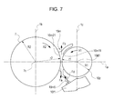
- FIG. 7 is an explanatory drawing illustrating a configuration of the developing apparatus.
- FIG. 8 is an explanatory drawing illustrating a configuration of the developing apparatus.
- FIG. 9 is a cross-sectional view of a spacer or the like.
- FIG. 10A is a cross-sectional view of the spacer or the like.
- FIG. 10B is an explanatory drawing illustrating an arrangement of the spacer in a longitudinal direction.
- the longitudinal direction of a process cartridge corresponds to a direction of an axial line of a developing roller (the direction parallel to a direction in which the axis of rotation extends).
- FIG. 2 is a pattern diagram illustrating a cross section of the image forming apparatus having a process cartridge of the embodiment disclosed here mounted thereon and, more specifically, a pattern diagram illustrating a cross section of a laser beam printer as a configuration of the image forming apparatus.
- an image forming apparatus (laser beam printer) A of Example 1 is configured to irradiate the photosensitive drum 7 having a drum shape with information light on the basis of image information from an optical system 1 as an optical device, and form an electrostatic latent image on the photosensitive drum 7 .
- the electrostatic latent image is developed by a developer (hereinafter, referred to as “toner”), and a toner image is formed.
- a recording medium for example, recording paper, OHP sheet, fabric and the like
- a recording medium 2 is fed from a cassette 3 a one by one separately by a pickup roller 3 b and a pressure-contact member 3 c in press contact thereto.
- the fed recording medium 2 is conveyed along a conveyance guide 3 f 1 to a transfer portion T where the photosensitive drum 7 of a process cartridge B and a transfer roller 4 as a transfer device oppose each other.
- the fixing device 5 includes a drive roller 5 a and a fixing rotating body 5 d having a heater 5 b integrated therein and is composed of a cylindrical seat which is rotatably supported by a supporting member 5 c , and fixes a toner image transferred by applying heat and pressure to the recording medium 2 passing therethrough.
- a discharge roller 3 d is configured to convey the recording medium 2 having the toner image fixed thereto and discharge the recording medium 2 to a discharge unit 6 through a reversal conveying path.
- the pickup roller 3 b , the pressure-contact member 3 c , the discharge roller 3 d , and the like constitute a conveying device 3 .
- FIG. 3 is a pattern diagram illustrating a cross section of the process cartridge of the embodiment disclosed here.
- a process cartridge B includes a drum unit 11 and a developing unit 10 coupled with the drum unit 11 .
- the drum unit 11 includes a photosensitive drum 7 and a drum frame member 11 d as a frame member for rotatably supporting the photosensitive drum 7 . Furthermore, the drum frame member 11 d includes a cleaning blade 11 a and a charging roller 8 integrated (supported) therein.
- the photosensitive drum 7 is an image bearing member configured to allow formation of an image (latent image, toner image) on a surface thereof.
- the drum unit 11 is an image bearing member unit configured to retain the image bearing member (the photosensitive drum 7 ).
- the developing unit 10 includes a developing roller 10 d and a developing frame 10 f 1 as a frame member configured to support the developing roller 10 d .
- the developing roller 10 d is a developer bearing member configured to bear developer for developing the latent image formed on the photosensitive drum.
- the developing frame 10 f 1 constitutes the frame member of the developing unit in cooperation with a toner frame member 14 .
- a toner chamber 10 a (developer storage portion) for storing toner (developer) is defined mainly by the toner frame member 14 .
- the toner frame member 14 includes a frame member body 14 a and a lid member 14 b configured to join with the frame member body 14 a.
- the developing unit 10 corresponds to a developing apparatus in Example 1.
- the developing apparatus (the developing unit 10 ) has a configuration detachably attachable with respect to an apparatus body of the image forming apparatus as part of the process cartridge.
- an image is formed in the following manner.
- the image forming apparatus is configured to rotate the photosensitive drum 7 having a photosensitive layer thereon, and apply a voltage to a charging roller 8 , which corresponds to a charging device, to charge the surface of the photosensitive drum 7 evenly.
- the charged photosensitive drum 7 is exposed through an exposure opening 9 b with information light (light image) on the basis of image information from the optical system 1 as illustrated in FIG. 2 .
- an electrostatic latent image is formed on the surface of the photosensitive drum 7 , and the electrostatic latent image is developed as a toner image (developer image) by the developing unit 10 .
- the image forming apparatus feeds toner in the toner chamber 10 a defined by the toner frame member 14 of the developing unit 10 to a developing chamber 10 i by a rotatable developer conveying member (hereinafter, referred to as a “toner feeding member”) 10 b and an elastic sheet 112 .
- the elastic sheet 12 is located in a region of rotation of the toner feeding member 10 b , and is configured to feed the toner to the developing chamber 10 i by coming into contact (interference) with the toner feeding member 10 b.
- the image forming apparatus rotates the developing roller 10 d having a fixed magnet 10 c integrated therein as illustrated in FIG. 3 .
- a toner layer provided with a frictional charge by a developing blade 10 e as a developer restricting member is formed on the surface of the developing roller 10 d .
- a toner image is formed and visualized.
- the image forming apparatus scraps off residual toner on the photosensitive drum 7 by a cleaning blade 11 a as a cleaning device. Simultaneously, the toner is scooped by a scooping sheet 11 b and is collected in a removed toner storing unit 11 c.
- the developing frame 10 f 1 includes arm portions 10 q 1 and 10 q 2 formed with coupling holes 10 s 1 and 10 s 2 at both end portions thereof.
- the developing unit 10 including the developing roller 10 d is rotatably supported by the drum unit 11 having the cleaning blade 11 a.
- the photosensitive drum 7 and the developing roller 10 d are allowed to move relative to each other.
- a predetermined pressing force f directed toward the drum unit 11 is applied to the developing unit 10 by the own weight of the developing unit 10 and a biasing member (such as a spring) provided between the developing unit 10 and the drum unit 11 .
- the developing unit 10 is biased in the direction in which the developing roller 10 d gets closer to the photosensitive drum 7 .
- an end seal 10 r configured to prevent leakage of toner from both end portions of the developing roller 10 d is mounted on the developing frame 10 f 1 .
- Spacers 10 m are disposed at end portions (both end portions) of the developing roller 10 d .
- the spacers 10 m come into abutment with the photosensitive drum 7 so that the developing roller 10 d face the photosensitive drum 7 in parallel thereto with a predetermined interval therewith.
- the spacer 10 m includes a developing roller contact surface 10 m 11 extending along the developing roller 10 d and a photosensitive drum contact surface 10 m 21 extending along the photosensitive drum 7 .
- the developing roller contact surface 10 m 11 and the photosensitive drum contact surface 10 m 21 are distance maintaining members configured to maintain the distance between the developing roller 10 d and the photosensitive drum 7 respectively constant by coming into contact with the developing roller 10 d and the photosensitive drum 7 .
- the developing roller contact surface 10 m 11 has an arcuate shape having a radius r 1 , which is substantially the same as the outer peripheral radius R 1 of the developing roller 10 d .
- the photosensitive drum contact surface 10 m 21 has a radius r 2 , which is substantially the same as the outer peripheral radius R 2 of the photosensitive drum 7 .
- the spacers 10 m are mounted on both end portions of the surface of the developing roller 10 d in the longitudinal direction as illustrated in FIG. 1 .
- the surface of the developing roller 10 d on which the spacers 10 m are mounted may be either portions on which the toner layer is formed or portions on which the toner layer is not formed.
- a biasing member 50 is provided between the spacer 10 m and the developing frame 10 f 1 , and the biasing member 50 is an elastic member and is formed of a substance having elasticity such as elastomer, rubber, and sponge.
- the biasing member 50 is an elastic deforming member (elastic member) which is elastically deformable.
- the biasing member 50 is fixed to the developing frame 10 f 1 , and comes into contact with the spacer 10 m . Part of the spacer 10 m is configured to dig into the biasing member 50 .
- the pressing force f illustrated in FIG. 3 brings the spacer 10 m into abutment with the surfaces of the developing roller 10 d at a developing roller sliding contact portion 10 p 11 and with the surface of the photosensitive drum 7 at the photosensitive drum contact surface 10 m 21 .
- the developing roller 10 d and the photosensitive drum 7 are held at a constant interval.
- the biasing member 50 which is an elastic member, is compressed between the spacer 10 m and the developing frame 10 f 1 , whereby the spacer 10 m receives a biasing force Fd illustrated in FIG. 4 from the biasing member 50 .
- the biasing force Fd is a force not smaller than “0”, directed toward the upstream side in the direction of rotation of the developing roller 10 d and the photosensitive drum 7 .
- a coefficient of elasticity and an amount of compression of the biasing member 50 are selected so as to allow the spacer 10 m to be positioned between the developing roller 10 d and the photosensitive drum 7 , whereby the biasing force Fd applied from the biasing member 50 to the spacer 10 m is adjusted.
- the developing roller 10 d and the photosensitive drum 7 rotate respectively in directions X 1 and X 2 in which peripheral surfaces thereof at opposing position (opposing surfaces) rotate in the same direction.
- the spacer 10 m receives a force Fa which acts to move the spacer 10 m to the downstream side of the direction of rotation of the developing roller 10 d and the photosensitive drum 7 by a sliding contact between the developing roller 10 d and the photosensitive drum 7 .
- the force Fa is determined by a frictional force generated on the developing roller contact surface 10 m 11 of the spacer 10 m and a frictional force generated on the photosensitive drum contact surface 10 m 21 .
- the spacer 10 m When the biasing member 50 , which is an elastic member, is compressed between the spacer 10 m and the developing frame 10 f 1 , the spacer 10 m receives a biasing force Fd, which acts to move the spacer 10 m to the upstream side of the direction of rotation of the developing roller 10 d and the photosensitive drum 7 from the biasing member 50 .
- the force Fd is a force against the force Fa.
- a pressing force f (see FIG. 3 ) generates a force Fb which acts to hold the spacer 10 m between the developing roller 10 d and the photosensitive drum 7 acting on the spacer 10 m .
- Fb a force which acts to hold the spacer 10 m between the developing roller 10 d and the photosensitive drum 7 acting on the spacer 10 m .
- the causes of the rise of the frictional force include abrasion of the spacer with long time of use, entry of foreign substances such as toner between the contact surfaces ( 10 m 11 and 10 m 21 ) and the developing roller 10 d or the photosensitive drum 7 , and other various causes.
- a force Fa which acts to move the spacer 10 m to the downstream side of the direction of rotation of the developing roller 10 d and the photosensitive drum 7 is increased, and may exceeds the force Fb by which the spacer 10 m is held between the developing roller 10 d and the photosensitive drum 7 .
- the spacer 10 m moves to the downstream side of the direction of rotation of the developing roller 10 d.
- the biasing member 50 which corresponds to an elastic member, is compressed between the spacer 10 m and the developing frame 10 f 1 , and applies a force Fa corresponding to the amount of movement of the spacer 10 m to the spacer 10 to bias the spacers 10 m to the upstream side of the direction of rotation of the developing roller 10 d.
- the biasing force from the biasing member 50 may keep the spacer 10 m at a position between the developing roller 10 d and the photosensitive drum 7 which does not cause a substantial image failure.
- the biasing member 50 is elastically deformed when the spacer 10 m acts to move in association with the rotation of the developing roller 10 d and the photosensitive drum 7 .
- the biasing member 50 applies a repulsive force (elastic force) that acts to cancel the elastic deformation to the spacer 10 m . Accordingly, the biasing member 50 biases the spacer 10 m toward the upstream side of the direction of rotation of the developing roller 10 d , and prevents the movement of the spacer 10 m.
- the biasing member 50 provided between the spacer 10 m and the developing frame 10 f 1 also has a function to restrict (prevent) the spacer 10 m to move to the downstream side of the direction of rotation of the developing roller 10 d or the photosensitive drum 7 when a vibration or an impact is applied to the developing unit 10 .
- the biasing member 50 provided between the spacer 10 m and the developing frame 10 f 1 contributes to prevent the spacer 10 m from moving in association with the rotation of the developing roller 10 d and the photosensitive drum 7 at the time of image formation by the elastic force of the biasing member 50 .
- the spacer 10 m can stay at a position between the developing roller 10 d and the photosensitive drum 7 which does not cause a substantial image failure.
- the spacer 10 m which is a SD gap guarantee member, is prevented from moving in association with the rotation of the developing roller 10 d and the photosensitive drum 7 , and the interval and the distance between the photosensitive drum 7 and the developing roller 10 d can be maintained stably.
- the developing roller contact surface 10 m 11 and the photosensitive drum contact surface 10 m 21 of the spacer have arcuate shapes having radii substantially the same as the outer peripheral radii of the developing roller 10 d and photosensitive drum 7 , respectively.
- this disclosure is not limited thereto, and the spacers 10 m having any shape may be suitably applied irrespective of the shapes of the developing roller contact surface 10 m 11 and the photosensitive drum contact surface 10 m 21 as long as the position of the spacer 10 m is fixed by being clamped between the developing roller 10 d and the photosensitive drum 7 .
- FIG. 9 is a cross-sectional view of the spacer 10 m of Example 1 taken along the line extending perpendicularly with respect to the center axis of the developing roller 10 d , and is a cross-sectional view equivalent to FIG. 4 .
- the spacer 10 m of Example 1 comes into contact with the photosensitive drum 7 and the developing roller 10 d both at the upstream side and the downstream side of a nearest position at which the distance between the developing roller 10 d and the photosensitive drum 7 is the shortest. Detailed description will be given below.
- the developing roller contact surface 10 m 11 comes into abutment with the developing roller 10 d over the substantially entire area. Consequently, the developing roller contact surface 10 m 11 comes into contact with the developing roller 10 d respectively at the upstream and at the downstream of the line 1 a in the direction of rotation X 1 of the developing roller 10 d .
- the line 1 a is a line connecting a center of rotation of the developing roller 10 d and a center of rotation of the photosensitive drum 7 .
- sliding contact portions of the spacer 10 m which comes into contact (sliding contact) with the developing roller 10 d includes a first developing roller sliding contact portion 10 p 11 located upstream of the line 1 a and a second developing roller sliding contact portion 10 p 12 located downstream of the line 1 a.
- Example 1 since the first developing roller sliding contact portion 10 p 11 and the second developing roller sliding contact portion 10 p 12 are on the same curved surface (developing roller contact surface 10 m 11 ), the first developing roller sliding contact portion 10 p 11 and the second developing roller sliding contact portion 10 p 12 are connected. However, the first developing roller sliding contact portion 10 p 11 and the second developing roller sliding contact portion 10 p 12 need not to be on the same plane, and may be separated.
- a sliding contact portions of the spacer 10 m which comes into contact (sliding contact) with the photosensitive drum 7 includes a first photosensitive drum sliding contact portion 10 p 21 located upstream of the line 1 a and a second photosensitive drum sliding contact portion 10 p 22 located downstream of the line 1 a.
- Example 1 since the two photosensitive drum sliding contact portion 10 p 21 , 10 p 22 are located on the same curved surface (photosensitive drum contact surface 10 m 21 ), the photosensitive drum sliding contact portion 10 p 21 , 10 p 22 are connected. However, the photosensitive drum sliding contact portion 10 p 21 , 10 p 22 need not to be on the same plane, and may be separated.
- Developing roller sliding contact portions 10 p 11 and 10 p 12 correspond to first and second developer bearing member sliding contact portions (developing side sliding contact portions) which come into sliding contact with the developer bearing member when the developer bearing member (the developing roller 10 d ) rotates.
- the photosensitive drum sliding contact portions 10 p 21 , 10 p 22 correspond to first and second image bearing member sliding contact portions (image bearing side sliding contact portions) which come into sliding contact with the image bearing member when the image bearing member (photosensitive drum 7 ) rotates.
- the distance between the developing roller 10 d and the photosensitive drum 7 is nearest on the line 1 a .
- the width of the spacer 10 m is larger than the shortest distance between the developing roller 10 d and the photosensitive drum 7 (the distance on the line 1 a )
- the movement of the spacer 10 m along the direction of rotation X 1 is restrained even when the developing roller 10 d rotates.
- the distance between the photosensitive drum sliding contact portion 10 p 21 and the developing roller sliding contact portion 10 p 11 is larger than the distance between the surfaces of the developing roller 10 d and the photosensitive drum 7 on the line 1 a . Therefore, the photosensitive drum sliding contact portion 10 p 21 and the developing roller sliding contact portion 10 p 11 come into contact with the photosensitive drum 7 and the developing roller 10 d to restrain the spacer 10 m from moving in directions of rotation X 1 and X 2 .
- Example 1 the spacer 10 m comes into contact with the photosensitive drum 7 at the photosensitive drum sliding contact portion 10 p 22 on the downstream side of the line 1 a , and comes into contact with the developing roller 10 d at the developing roller sliding contact portion 10 p 12 on the downstream side of the line 1 a . Therefore, the spacer 10 m does not move to the opposite side of the direction of rotation of the developing roller 10 d .
- the spacer 10 m includes the photosensitive drum sliding contact portion 10 p 21 and the developing roller sliding contact portion 10 p 11 . Therefore, even when the developing roller 10 d rotates, the spacer 10 m does not move easily in the direction of rotation thereof.
- the developing roller 10 d and the photosensitive drum 7 rotate so as to move opposing surfaces thereof in the same direction. Therefore, a strong force is applied to the spacer 10 m from the beginning in the directions of rotation X 1 and X 2 of the developing roller 10 d and the photosensitive drum 7 . Therefore, in Example 1, in order to restrain the movement of the spacer 10 m more reliably, the biasing member 50 is provided on the developing frame 10 f 1 .
- the biasing member 50 constitute a rotation preventing unit portion, which prevents the movement of the spacer 10 m together with the photosensitive drum sliding contact portion 10 p 21 and the developing roller sliding contact portion 10 p 11 .
- the rotation preventing unit portions ( 50 , 10 p 21 , 10 p 11 ) prevent the spacer 10 m from moving in the direction of rotations X 1 and X 2 .
- the photosensitive drum sliding contact portions 10 p 21 , 10 p 22 of the photosensitive drum contact surface 10 m 21 and the developing roller sliding contact portions 10 p 11 and 10 p 12 of the developing roller contact surface 10 m 11 correspond to the distance maintaining members that maintain the distance between the developing roller 10 d and the photosensitive drum 7 to be constant.
- the positions of the respective sliding contact portions do not move, so that the distance between the photosensitive drum 7 and the developing roller 10 d is stably maintained by the spacer 10 m.
- the process cartridge explained in Example 1 has a configuration of forming a monochrome image.
- this disclosure is not limited thereto.
- a configuration in which a process cartridge includes a plurality of developing devices and forms images having a plurality of colors is also applicable.
- An electrophotographic photosensitive member is not limited to the photosensitive drum and, for example, following members.
- a photoconductor is used as the photosensitive member, and the photoconductor include, for example, amorphous silicon, amorphous selenium, zinc oxide, titanium oxide, and organic photoconductor (OPC).
- OPC organic photoconductor
- Examples of the shape of a member on which the photosensitive member is mounted include a drum shape and a belt shape.
- the drum-shaped photosensitive member is achieved by depositing or coating the photoconductor on a cylinder formed of aluminum alloy or the like.
- non-contact type chargers such as a corona charger, which does not come into contact with the photosensitive drum, may be employed as alternative configurations.
- the charging device may be a blade (a charging blade), a pad type, a block type, a rod type, a wire type instead of the roller type as described above.
- a cleaning device may be configured by using a blade, a far brush, a magnetic blush, or the like.
- the process cartridge described above means a member including at least the image bearing member and the developing device (developing apparatus) integrated into a cartridge and being configured to be detachably attachable to the apparatus body of the image forming apparatus. Then, the process cartridge may be detachably attached to the main body of the apparatus by a user by himself or herself. Therefore, maintenance of the main body of the apparatus may be performed by a user by himself or herself.
- the spacer 10 m is not applied only to the process cartridge.
- the spacer 10 m of Example 1 may be applied even to a configuration in which the image bearing member (the photosensitive drum) and the developing apparatus are fixed to the image forming apparatus and the user does not replace these members.
- the process cartridge including the drum unit and the developing unit (developing apparatus) integrated therein has been exemplified.
- this disclosure is not limited thereto.
- the laser beam printer is exemplified as the electrophotographic image forming apparatus.
- the present invention is not limited thereto.
- this disclosure may also be applied as a matter of course to the electrophotographic image forming apparatuses such as electrophotographic copying machines, electrophotographic printers such as LED printers, facsimile apparatuses, word processors, or copying machines including these apparatuses (multifunction printers and the like).
- the biasing member 50 is fixed to the developing frame 10 f 1 .
- the biasing member 50 may be fixed to other portions of the developing unit 10 .
- the biasing member 50 may be fixed to another member supported by the developing frame 10 f 1 .
- Example 2 of this disclosure will be described with reference to FIG. 3 , and FIG. 6 to FIG. 8 .
- Example 2 configurations and actions different from the example described above will be described, and components having the same configurations and functions are designated by the same reference numerals and description of the above-described example will be incorporated. Description will be incorporated by assigning the same component names.
- Example 1 the biasing member 50 is provided on the developing frame 10 f 1 .
- part of the spacer 10 m corresponds to a biasing member 10 m 5 as illustrated in FIG. 6 .
- the biasing member 10 m 5 is configured integrally with the spacer 10 m .
- Example 2 is not limited to such a configuration, and the biasing member 50 may be a member separate from a body portion of the spacer 10 m as long as the biasing member 10 m 5 is provided on the spacer 10 m . In such a case, the biasing member 50 may be fixed to the body portion of the spacer 10 m with an adhesive agent.
- the biasing member 10 m 5 has an elasticity, and comes into contact with the developing frame 10 f 1 .
- the biasing unit 10 m 5 of Example 2 is also a member configured to bias the spacer 10 m toward the upstream side of the direction of rotation of the developing roller 10 d by an elastic force generated by being elastically deformed. Description will be given below.
- the pressing force f illustrated in FIG. 3 brings the spacer 10 m into abutment with the surfaces of the developing roller 10 d at a developing roller sliding contact portion 10 p 11 at the developing roller contact surface 10 m 11 and brings the same into abutment with the surface of the photosensitive drum 7 at the photosensitive drum contact surface 10 m 21 .
- the developing roller 10 d and the photosensitive drum 7 are held at a constant interval.
- the biasing member 10 m 5 having elasticity is compressed between the spacer 10 m and the developing frame 10 f 1 .
- spacer 10 m receives a biasing force Fd from the biasing member 10 m 5 in FIG. 7 .
- the biasing force Fd is a force not smaller than “0”, directed toward the upstream side in the direction of rotation of the developing roller 10 d and the photosensitive drum 7 .
- a coefficient of elasticity and an amount of compression of the biasing member 10 m 5 having elasticity are selected so as to allow the spacer 10 m to be positioned between the developing roller 10 d and the photosensitive drum 7 , whereby the magnitude of the biasing force Fd is adjusted.
- the developing roller 10 d and the photosensitive drum 7 rotate respectively in directions X 1 and X 2 in which peripheral surfaces thereof at opposing position rotate in the same direction.
- the spacer 10 m receives a force Fa which acts to move the spacer 10 m to the downstream side of the direction of rotation of the developing roller 10 d and the photosensitive drum 7 by a sliding contact between the developing roller 10 d and the photosensitive drum 7 .
- the force Fa is determined by a frictional force generated on the developing roller contact surface 10 m 11 of the spacer 10 m and a frictional force generated on the photosensitive drum contact surface 10 m 21 .
- the spacer 10 m When the biasing member 10 m 5 having elasticity is compressed between the spacer 10 m and the developing frame 10 f 1 , the spacer 10 m receives a biasing force Fd, which acts to move the spacer 10 m to the upstream side of the direction of rotation of the developing roller 10 d and the photosensitive drum 7 from the biasing member 10 m 5 .
- the force Fd is a force against the force Fa.
- a pressing force f generates a force Fb which acts to hold the spacer 10 m between the developing roller 10 d and the photosensitive drum 7 acting on the spacer 10 m .
- Fb a force which acts to hold the spacer 10 m between the developing roller 10 d and the photosensitive drum 7 acting on the spacer 10 m .
- a force Fa which acts to move the spacer 10 m to the downstream side of the direction of rotation of the developing roller 10 d and the photosensitive drum 7 is increased, and exceeds a force Fb by which the spacer 10 m is held between the developing roller 10 d and the photosensitive drum 7 . Consequently, the spacer 10 m moves to the downstream side of the direction of rotation of the developing roller 10 d.
- the biasing member 10 m 5 having elasticity is compressed between the spacer 10 m and the developing frame 10 f 1 , and applies a force Fb corresponding to the amount of movement of the spacer 10 m to the spacer 10 to bias the spacers 10 m to the upstream side of the direction of rotation of the developing roller 10 d.
- the biasing force from the biasing member 10 m 5 may keep the spacer 10 m at a position between the developing roller 10 d and the photosensitive drum 7 which does not cause a substantial image failure.
- the biasing member 10 m 5 provided between the spacer 10 m and the developing frame 10 f 1 also has a function to restrict the spacer 10 m to move to the downstream side of the direction of rotation of the developing roller 10 d or the photosensitive drum 7 when a vibration or an impact is applied to the developing unit 10 .
- the biasing member 10 m 5 provided on part of the spacer 10 m contributes to prevent the spacer 10 m from moving in association with the rotation of the developing roller 10 d and photosensitive drum 7 at the time of image formation by the elastic force of the biasing member 10 m 5 .
- the spacer 10 m can stay at a position between the developing roller 10 d and the photosensitive drum 7 which does not cause a substantial image failure by the biasing member 10 m 5 .
- the spacer 10 m is prevented from moving in association with the rotation of the developing roller 10 d and the photosensitive drum 7 , and the distance between the photosensitive drum 7 and the developing roller 10 d can be maintained stably.
- biasing member 10 m 5 comes into contact with the developing frame 10 f 5
- a configuration in which the developing frame 10 f 5 comes into contact with other portions of the developing unit 10 is also applicable.
- the biasing member 10 m 5 may come into contact with a separate member supported by the developing frame 10 f 5 .
- Example 1 a configuration in which the developing roller 10 d and the photosensitive drum 7 are arranged at a constant space (gap) between the surfaces of each other, that is, a configuration in which the non-contact type developing method is employed has been described.
- this disclosure is not limited thereto.
- a spacer 10 m described in the above described Examples may be employed in a contact type developing method as illustrated in FIGS. 10A and 10B .
- FIG. 10A is a cross-sectional view of the spacer and the developing roller taken along a line perpendicular to the axis of rotation of the developing roller 10 d .
- FIG. 10B is an explanatory drawing illustrating an arrangement of the spacer 10 m in the longitudinal direction of the developing roller 10 d.
- the developing roller 10 d includes an aluminum sleeve 10 d 2 and a rubber layer (elastic member) 10 d 3 provided on the surface thereof.
- the spacer 10 m is provide at both end portions of the aluminum sleeve 10 d 2 .
- a rubber layer 10 d 33 of the developing roller 10 d is in contact with the photosensitive drum 7 by being compressed by a certain amount.
- the spacer 10 m maintains the distance between the developing roller 10 d and the photosensitive drum 7 (the distance between centers of the both) to be constant in a state in which the surfaces of the developing roller 10 d and the photosensitive drum 7 are in contact with each other, whereby the amount of compression of the rubber layer 10 d 3 is maintained to be constant.
- the biasing member 50 is fixed to the developing frame 10 f 1 , and is in contact with the spacer 10 m .
- the biasing member 50 is pushed and compressed by the spacer 10 m when the spacer 10 m act to move along the direction of rotation X 1 of the developing roller 10 d when the developing roller 10 d rotates.
- a biasing force (elastic force) Fd generated by the biasing member 50 being compressed is applied to the spacer 10 m from the biasing member 50 .
- the spacer 10 m is prevented from moving in the direction of rotation X 1 , returns to its original position (the position where the distance between the developing roller 10 d and the photosensitive drum 7 is maintained), and is kept at this position.
- the interval guarantee member is prevented from moving when the developer bearing member rotates in a simple configuration.
Landscapes
- Physics & Mathematics (AREA)
- General Physics & Mathematics (AREA)
- Dry Development In Electrophotography (AREA)
- Engineering & Computer Science (AREA)
- Computer Vision & Pattern Recognition (AREA)
- Electrophotography Configuration And Component (AREA)
Abstract
Description
Claims (20)
Applications Claiming Priority (2)
| Application Number | Priority Date | Filing Date | Title |
|---|---|---|---|
| JP2013125717A JP2015001602A (en) | 2013-06-14 | 2013-06-14 | Developing device, process cartridge, and interval guarantee member |
| JP2013-125717 | 2013-06-14 |
Publications (2)
| Publication Number | Publication Date |
|---|---|
| US20140369720A1 US20140369720A1 (en) | 2014-12-18 |
| US9229358B2 true US9229358B2 (en) | 2016-01-05 |
Family
ID=52019330
Family Applications (1)
| Application Number | Title | Priority Date | Filing Date |
|---|---|---|---|
| US14/302,245 Expired - Fee Related US9229358B2 (en) | 2013-06-14 | 2014-06-11 | Developing apparatus, process cartridge, and interval guarantee member |
Country Status (2)
| Country | Link |
|---|---|
| US (1) | US9229358B2 (en) |
| JP (1) | JP2015001602A (en) |
Families Citing this family (1)
| Publication number | Priority date | Publication date | Assignee | Title |
|---|---|---|---|---|
| JP6859643B2 (en) * | 2016-09-28 | 2021-04-14 | 富士ゼロックス株式会社 | Image forming equipment, developing equipment and bearings |
Citations (4)
| Publication number | Priority date | Publication date | Assignee | Title |
|---|---|---|---|---|
| US6044235A (en) * | 1995-04-21 | 2000-03-28 | Canon Kabushiki Kaisha | Process cartridge having raised fabric-like cleaning member |
| JP3679665B2 (en) | 1999-11-19 | 2005-08-03 | キヤノン株式会社 | Gap assurance member, developing device, charging device, and process cartridge |
| US20140314444A1 (en) * | 2013-04-23 | 2014-10-23 | Canon Kabushiki Kaisha | Interval securing member, developing apparatus, and process cartridge |
| US20140314439A1 (en) * | 2013-04-23 | 2014-10-23 | Canon Kabushiki Kaisha | Developing device, process cartridge, and image forming apparatus |
-
2013
- 2013-06-14 JP JP2013125717A patent/JP2015001602A/en active Pending
-
2014
- 2014-06-11 US US14/302,245 patent/US9229358B2/en not_active Expired - Fee Related
Patent Citations (4)
| Publication number | Priority date | Publication date | Assignee | Title |
|---|---|---|---|---|
| US6044235A (en) * | 1995-04-21 | 2000-03-28 | Canon Kabushiki Kaisha | Process cartridge having raised fabric-like cleaning member |
| JP3679665B2 (en) | 1999-11-19 | 2005-08-03 | キヤノン株式会社 | Gap assurance member, developing device, charging device, and process cartridge |
| US20140314444A1 (en) * | 2013-04-23 | 2014-10-23 | Canon Kabushiki Kaisha | Interval securing member, developing apparatus, and process cartridge |
| US20140314439A1 (en) * | 2013-04-23 | 2014-10-23 | Canon Kabushiki Kaisha | Developing device, process cartridge, and image forming apparatus |
Also Published As
| Publication number | Publication date |
|---|---|
| JP2015001602A (en) | 2015-01-05 |
| US20140369720A1 (en) | 2014-12-18 |
Similar Documents
| Publication | Publication Date | Title |
|---|---|---|
| JP5319178B2 (en) | Paper feeding device and image forming apparatus | |
| JP5073454B2 (en) | Lubricant coating apparatus, process cartridge, and image forming apparatus | |
| US9098012B2 (en) | Electrophotographic image forming apparatus and process cartridge | |
| US8019259B2 (en) | Development device, process unit, and image forming apparatus | |
| JP4501842B2 (en) | Image forming apparatus | |
| US6181897B1 (en) | Developing apparatus | |
| US10551762B2 (en) | Image forming apparatus having guiding member for regulating approach of recording material toward transfer belt | |
| JP6120049B2 (en) | SEALING MECHANISM, DEVELOPING DEVICE, PROCESS UNIT, AND IMAGE FORMING DEVICE | |
| US9904214B2 (en) | Image forming apparatus having transfer belt configured to avoid image defects | |
| US9840387B2 (en) | Belt conveyance apparatus and image forming apparatus | |
| US9335719B2 (en) | Interval securing member, developing apparatus, and process cartridge | |
| US8867971B2 (en) | Developer regulator, development device, and image forming apparatus incorporating same | |
| JP2009288643A (en) | Cleaning member, charging apparatus, process cartridge and image forming apparatus | |
| US9229358B2 (en) | Developing apparatus, process cartridge, and interval guarantee member | |
| JP2008089771A (en) | Cleaning method, process cartridge, and image forming apparatus | |
| JP5800220B2 (en) | Image forming apparatus | |
| US9996041B2 (en) | Belt feeding device and image forming apparatus | |
| JP3632245B2 (en) | Color image forming apparatus | |
| JP6188459B2 (en) | Spacing guarantee member, developing device, process cartridge | |
| US11520275B2 (en) | Cleaning device capable of suppressing that a sealing member constitutes a resistance to a rotational operation of a supporting member for a cleaning blade | |
| JP7471945B2 (en) | Image forming device | |
| JP4821245B2 (en) | Image forming apparatus | |
| JP7000936B2 (en) | Developing equipment and image forming equipment | |
| JP2017167258A (en) | Bearing, developing device, process unit, and image forming apparatus | |
| JP2025075517A (en) | Lubricant supplying device and image forming apparatus |
Legal Events
| Date | Code | Title | Description |
|---|---|---|---|
| AS | Assignment |
Owner name: CANON KABUSHIKI KAISHA, JAPAN Free format text: ASSIGNMENT OF ASSIGNORS INTEREST;ASSIGNOR:OGINO, HIROKI;REEL/FRAME:033834/0691 Effective date: 20140528 |
|
| ZAAA | Notice of allowance and fees due |
Free format text: ORIGINAL CODE: NOA |
|
| ZAAB | Notice of allowance mailed |
Free format text: ORIGINAL CODE: MN/=. |
|
| STCF | Information on status: patent grant |
Free format text: PATENTED CASE |
|
| MAFP | Maintenance fee payment |
Free format text: PAYMENT OF MAINTENANCE FEE, 4TH YEAR, LARGE ENTITY (ORIGINAL EVENT CODE: M1551); ENTITY STATUS OF PATENT OWNER: LARGE ENTITY Year of fee payment: 4 |
|
| FEPP | Fee payment procedure |
Free format text: MAINTENANCE FEE REMINDER MAILED (ORIGINAL EVENT CODE: REM.); ENTITY STATUS OF PATENT OWNER: LARGE ENTITY |
|
| LAPS | Lapse for failure to pay maintenance fees |
Free format text: PATENT EXPIRED FOR FAILURE TO PAY MAINTENANCE FEES (ORIGINAL EVENT CODE: EXP.); ENTITY STATUS OF PATENT OWNER: LARGE ENTITY |
|
| STCH | Information on status: patent discontinuation |
Free format text: PATENT EXPIRED DUE TO NONPAYMENT OF MAINTENANCE FEES UNDER 37 CFR 1.362 |
|
| FP | Lapsed due to failure to pay maintenance fee |
Effective date: 20240105 |